
95% of researchers rate our articles as excellent or good
Learn more about the work of our research integrity team to safeguard the quality of each article we publish.
Find out more
ORIGINAL RESEARCH article
Front. Phys. , 22 June 2023
Sec. Optics and Photonics
Volume 11 - 2023 | https://doi.org/10.3389/fphy.2023.1198092
This article is part of the Research Topic Advanced High Power Solid-State Laser Technology View all 9 articles
 Yao Lu1Zongfu Jiang1,2,3*Hu Xiao1,2,3Zilun Chen1,2,3Man Jiang1,2,3Junyu Chai1Hao Yang1Lianchuang Ding1Dan Zhang1,2,3Jiangbin Zhang1,2,3Qiong Zhou1,2,3Wenguang Liu1,2,3*
In this study, a method of stabilizing the output beam of a large-mode-area fiber amplifier operating above the mode instability threshold is demonstrated. A mode control system based on the photonic lantern is used to excite dynamic mode beatings as the seeding stage of a 42/250 µm Yb-doped fiber amplifier. We propose a theoretical explanation for the validity of this method: provided that the mode interference patterns generated by input mode beatings are antisymmetric to those in the main amplifier caused by thermally induced non-linear effects, the refractive index grating will not be formed to indicate the onset of mode instability. Experimentally, significant mode stability and beam quality improvement have been achieved in this system at power levels of up to nearly four times the mode instabilities threshold.
High-power fiber lasers and amplifiers are needed in numerous applications, such as gravitational wave detection [1], coherent lidar systems [2], space optical communication [3], and high-energy industrial manufacturing [4]. Driven by these applications, the demands on power scaling implicitly lead to multimode operation in which the non-linear effects can be mitigated with the increase in the mode-field diameters [5]. However, the onset of transverse mode instability (TMI) leads to significant power transfer from the fundamental mode (FM) to higher-order modes (HOMs) as soon as the large-mode-area (LMA) system characteristic threshold power has been reached [6]. Since the first observation of TMI, significant effort has been made to provide theoretical explanations and mitigation strategies for TMI [7]. One widely accepted theoretical explanation is that there are two conditions necessary to lead to TMI: the appearance of a (thermally induced) refractive index grating (RIG) written by the mode interference pattern (MIP) and a phase shift between them [8]. Thus, TMI mitigation strategies have been proposed aiming at reducing the strength of the RIG or manipulating the phase shift, such as designing special structure fiber [9–11], shifting pump wavelength [12], optimizing the fiber coiling methods [13], suppressing the noise property [14], and using gain-tailoring techniques [15]. Nevertheless, the aforementioned strategies have strict requirements for the active fiber or the structure of the amplifier. The Jena group used pump modulation to mitigate TMI in rode-type fiber-assisted amplifiers [16]. This method requires that the pump source can be modulated with kHz bandwidth, which increases the cost of the pump sources and power drivers and thus limits the application range. In 2013, Otto first proposed and verified that the formation of RIG could be damaged by actively controlling high-order mode excitation [17]. By using an acousto-optic deflector and the lens, the signal beam was injected into two symmetrical positions above and below the centerline of the main amplifier fiber. However, due to the introduction of the space optical path, the system structure was complicated and the stability was poor. In 2016, an all-fiber-based adaptive optics system based on the photonic lantern [18] was demonstrated. By splicing the output of the photonic lantern with the pump-signal combiner, 1 kW output in multimode fiber (MMF) with a 25 µm core diameter was realized [19]. In the previously reported work, the number of photonic lantern channels is very small and the controllable size of output fiber core diameter (just 25 µm) and the number of modes (just three) are limited. In addition, no beam quality data are provided to evaluate the control effect. In order to meet the application requirements of fiber laser with higher power and better beam quality, it is urgent to analyze the feasibility and scalability of the photonic-lantern-based mode control system.
In this work, we present a method of mitigating TMI using the photonic lantern [20] on the seeding stage of a common step-index active-fiber-assisted amplifier with a 42-µm-core-diameter output fiber. A mode control system [21] is set up to excite appropriate mode-beating seeds by actively modulating the input phase of a 5 × 1 photonic lantern according to the signal fed back from the detector at the output end. These mode beatings (formed by up to five different modes) can be dynamic and switched quickly enough to form the MIPs, which can counteract the MIPs in active fiber caused by thermally induced non-linear effects. As a result, the stable beam profile and beam quality improvement are experimentally achieved in a 42/250 µm Yb-doped fiber (YDF) amplifier at power levels of up to nearly four times the threshold of mode instabilities.
The schematic of the experimental setup is depicted in Figure 1. The seed source is a linearly polarized fiber laser with a center wavelength of 1,064 nm. The beam is split into five channels with phase modulators, commercial pre-amplifiers, isolators, and band-pass filters (fiber type in the end of the aforementioned devices: 10/125 μm, NA = 0.075). A circulator is inserted in one of the channels to detect the backward-propagating laser. All aforementioned components are operated in single mode. The photonic lantern is placed, which works as a linear optical device that converts the beam from a group of single-mode fibers (SMFs) to an MMF. As shown in Figure 1, the 5 × 1 photonic lantern consists of a tapered SMF bundle (10/130 μm, NA = 0.08) inside a low-index tube and an MMF fiber (30/130 μm, NA = 0.065). The detailed fabrication process and performance test of the photonic lantern can be found in [21]. The output fiber of the photonic lantern is spliced with the signal input port (30/130 µm) of the (6 + 1) × 1 pump and signal combiner. A total of six 976-nm LDs are combined to pump the 1.5-m-long YDF (42/250 μm, NA = 0.075) via this combiner with a 30/250 µm output port. The pump absorption coefficient of the YDF is approximately 21 dB/m @ 976 nm. The detailed segmented splicing scheme can be found in [22]. Finally, the collimated laser is output through a quartz block holder (QBH). CCD is used to collect near-field information in real-time, while the detector with pinhole is used to provide the controller with the power in bucket (PIB) as an evaluation function. The stochastic parallel gradient descent (SPGD) algorithm is chosen to drive the phase modulation in the controller. A detailed description of the effectiveness of the SPGD algorithm in the mode control system can be found in [23].
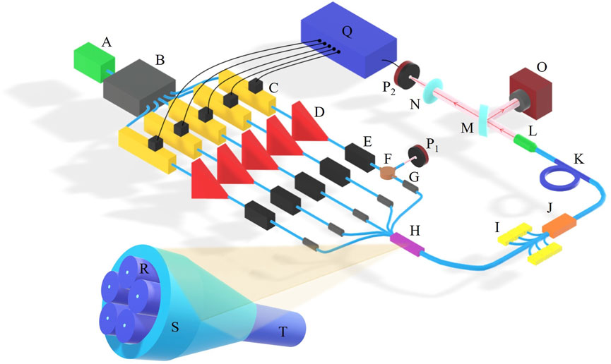
FIGURE 1. Schematic of the experimental setup and the 5 × 1 photonic lantern. A: Source, B: splitter, C: phase modulators, D: pre-amplifiers, E: isolators, F: circular, G: band-pass filters, H: photonic lantern, I: 976 nm LDs, J: pump and signal combiner, K: Yb-doped fiber (42/250 µm), L: quartz block holder, M: beam splitter, N: lens, O: CCD, P1 and P2: detectors, Q: controller, R: five single-mode fibers (10/130 µm), S: capillary tube, and T: multi-mode fiber (30/130 µm).
The main idea behind our mitigation strategy is exciting appropriate mode beatings as the seed of the main amplifier to counteract the MIP in the active fiber and wash out the thermally induced refractive index grating. LMA fiber generally supports the propagation of more than one transverse mode due to current technological limitations in the fabrication process and the disturbance of the external environment. These modes will propagate along the fiber with different phase velocities. Thus, the mode beatings of FMs and HOMs have appeared. We use the beam propagation method (BPM) to calculate the MIP created by these mode beatings in LMA fiber. For the optical field generated by the linearly polarized fiber, the linearly polarized (LP) modes are proposed which are a set of orthogonal complete bases of the light field in this system. Figure 2 shows the excitation beam profiles and interference patterns along the propagation of different LP mode beatings are as follows: (A) LP01 and LP11o with equal amplitudes and zero phase difference; (B) LP01 and LP11o with equal amplitudes and π/2 phase difference; (C) LP01 and LP21o with equal amplitudes and zero phase difference; and (D) LP01 and LP11o with an amplitude ratio of 9:1 and zero phase difference. Black arrows indicate the propagation direction of the beam in the fiber. The comparison of Figures 2A, B shows that when the mode components and contents remain unchanged, the phase difference between them can only shift MIP. The comparison of Figures 2A, C shows that when the mode components participating in mode beating change, both the pattern and beating frequency of MIP will change. The comparison of Figures 2A, D shows that when the components participating in mode beating remain unchanged but the mode contents are different, the MIP pattern will change but the beating frequency will remain the same. Therefore, in high-power systems, mode components, contents, and phase differences will all affect the distribution of MIP along the propagation direction, changing the formation of thermally induced RIG. Our aim is to excite a particular mode beating whose MIP is exactly antisymmetric to the MIP formed in the main amplifier caused by fiber process defects and environmental disturbances. In addition, the right mode beating needs to be generated dynamically and quickly enough that the heat load does not have enough time to completely mimic the alternating interference patterns. This way, thermally induced RIG is washed out in a kind of instable equilibrium. The adaptive control system based on the photonic lantern just meets the aforementioned mode control requirements.
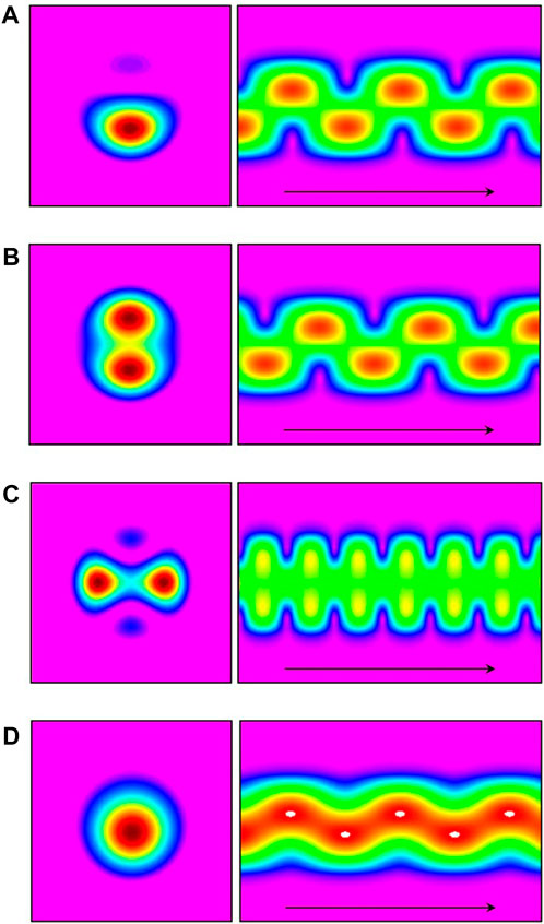
FIGURE 2. Excitation beam profiles and interference patterns created by the mode beatings of the fundamental and high-order modes. (A) LP01 and LP11o with equal amplitudes and zero phase difference; (B) LP01 and LP11o with equal amplitudes and π/2 phase difference; (C) LP01 and LP21o with equal amplitudes and zero phase difference; and (D) LP01 and LP11o with an amplitude ratio of 9:1 and zero phase difference. Black arrows indicate the propagation direction of the beam in the fiber.
The photonic lantern is an all-fiber-based linear optical element that allows for a low-loss mode evolution from a bundle of tapered SMFs into an MMF. If the taper region is long enough, the photonic lantern can be regarded as an adiabatic mode converter, and there will be one-to-one correspondence between the input and output fields. This characteristic makes photonic lanterns well applied in the mode control system. In order to lock the desired output, the idea of adaptive optics (AO) technology is used. In order to get the desired output light field, it is necessary to actively modulate the properties of the input field and detect the evaluation function at the output end in real time, aiming at making it converge to the optimal value. In simulation, the active modulation object is the phase of each input channel (the amplitude of each channel can be modulated offline according to the transmission matrix of the photonic lantern [21] by applying the appropriate current to the pre-amplifiers), and the evaluation function is the consistency between the output result and the control target. The mode control capability of this 5 × 1 photonic lantern system is simulated, as shown in Figure 3. The control target in Figures 3A–D, respectively, corresponds to the mode beatings in Figures 2A–D. Figures 3E, F show the convergence curves when the fundamental mode content of the control target is 10%–100% (with an interval of 10%), where each curve represents the average value of 50 calculations and the control target of each calculation is the superposition field of the four HOMs with random contents and the fundamental mode with fixed content. Figure 3 shows that any superposition of the five lowest LP modes can be basically generated within 60 loops. The system control bandwidth is the ratio of single iteration bandwidth to iteration loops. The single iteration bandwidth of the controller applied in our study is greater than 1 MHz, so the system control bandwidth is more than 16.67 kHz, which meets the requirement of mitigating TMI. In particular, as shown in Figure 3F, the higher the LP01 mode content of the control target, the better the consistency between the control result and the target. In fact, in the seeding stage of the fiber amplifiers, the general order of HOMs is low (<5), and their energy is very small (generally less than 5%) [7]. Therefore, the mode adaptive control system based on the photonic lantern can meet the needs of exciting appropriate mode beatings. These mode beatings can form the MIPs to exactly counteract the MIPs in the main amplifier caused by thermally induced non-linear effects so that RIG is not formed and mode instability does not occur. In particular, to mitigate TMI, we do not consider the specific mode superposition field at the end of the photonic lantern (i.e., the input field of the master amplifier) but the output field at the end of the entire system. Therefore, the photonic lantern and the master amplifier can be viewed collectively as a black box [24]. The ultimate control target is the fundamental mode, so the detector should collect the PIB of the output beam by QBH to provide an evaluation function for the controller, as shown in Figure 1.
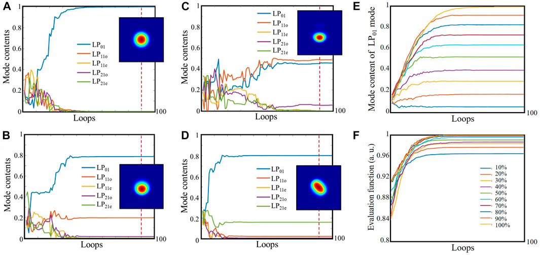
FIGURE 3. Control effect of the photonic lantern-based mode control system (mode content variation curves and near-field spots collected at the time indicated by the red dotted line) when targeting different mode beatings. (A) Control target 1: pure LP01 mode; (B) control target 2: 80% LP01 + 20% LP11o; (C) control target 3: 50% LP01 + 50% LP11o; (D) control target 4: 80% LP01 + 20% LP21e; and (E,F) convergence curves when the fundamental mode content of the control target is 10%–100%.
To verify the TMI mitigation effectiveness of this strategy, comparison experiments are carried out between using conventional and photonic lantern seeding. The TMI power threshold is determined by using the method introduced in [7] by calculating the standard deviation of the output power. In 2011, M. Laurila studied the influence of photodarkening on TMI and pointed out that for fiber with high pump absorption, the threshold power of TMI will start to decrease with the increase in test times and eventually stabilize around a saturation value [25]. Therefore, in this paper, mode instability occurs at least five times by power scaling before the measurement is carried out, to ensure that the TMI power threshold of the laser has stabilized to the saturation value. The TMI power threshold (Pthr) of the amplifier is measured when the conventional seed is used. Replacing the section between the beam splitter and the photonic lantern in the existing system in Figure 1 with a single conventional seed channel containing a pre-amplifier, an isolator, and a bandpass filter, the threshold of this amplifier using conventional seeding is measured: Pthr = (102 ± 5) W. At this time, the output power monitored by the power meter starts to fluctuate continuously; the ratio of the standard deviation to the average power is higher than 0.1‰/W. As shown in Figure 4A, when the output power is scaled to 75 W, the temporal trace of the output beam remains nearly stable. When the output power is 194 W (Figure 4B), obvious fluctuations in the temporal trace occur, and there is a characteristic frequency (782 Hz) in Fourier spectra, indicating the onset of TMI effect.
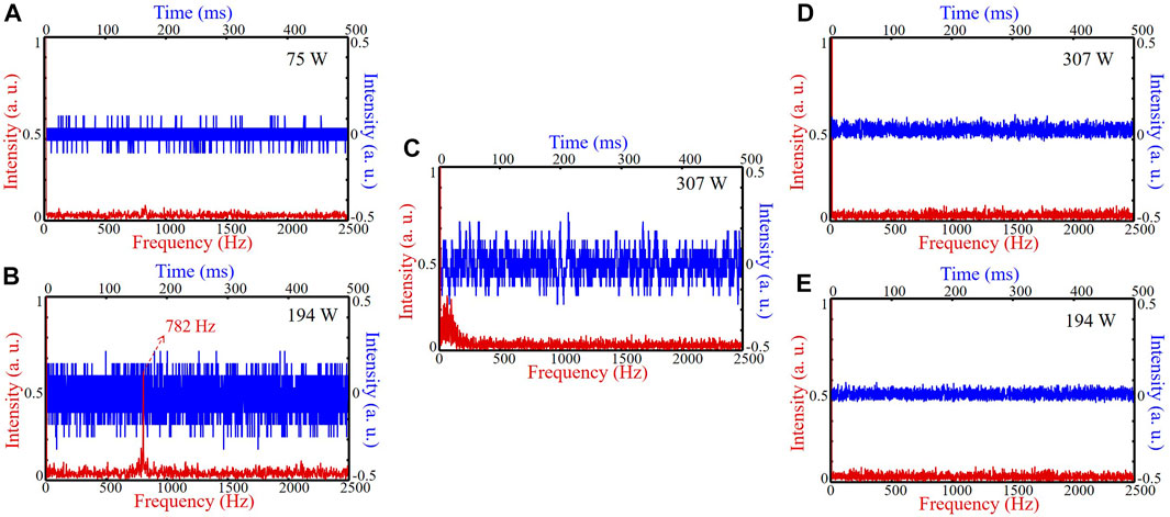
FIGURE 4. Temporal trace (blue line) and Fourier spectra (red line) of the output beam measured at (A) 75 W (below the TMI threshold) or (B) 194 W (above the TMI threshold) in the amplifier using conventional seed; in the amplifier using the photonic lantern mode control system as seed: (C) when the controller is turned off (measured at 307 W) and (D,E) when the controller is turned on (measured at 307 W and 194 W).
By using the photonic lantern on the seeding stage of the same amplifier, TMI does not occur even as the power is scaled to 403 W. When the controller of the system is turned off, the phases of the beam at the photonic lantern input channels are unlocked, producing a mode coupling beam at the output end. As shown in Figure 4C (measured at 307 W), the temporal trace is clearly up and down, indicating the power transfer from the FM to HOMs at a frequency of less than 200 Hz. We speculate that the output beam at this time presents a new mode instability state, which is not only caused by the thermal effect in the gain fiber but also by the constantly fluctuating superimposed field seeds provided by the photonic lantern when the controller is turned off. When the controller is turned on, the phases are locked immediately, as shown in Figures 4D, E (measured at 307 W and 194 W, respectively), the temporal trace remains nearly stable, and there is no characteristic frequency in the Fourier spectra. The temperature distribution of the YDF is uniform (slightly higher at the splicing point and the section with a smaller bend radius), indicating that periodic temperature distribution and RIG are not generated. Comparing Figures 4B, E, the temporal trace showed a significantly lower fluctuation range with no characteristic frequency in Fourier spectra, and TMI was effectively mitigated by using the photonic-lantern-based mode control system.
The beam quality of the output beam is also improved by using photonic lantern seeding. As shown in Figure 5A, by using conventional seeding, the far-field spot distorts significantly and gradually moves away from the Gaussian-like profile with the scaling of the output power. In particular, the spots measured above the TMI threshold are not stable; only one-frame photographs are presented here, and the far-field spots are distinctly segmented and enlarged. Video 1 shows the change in the near-field spot measured at 307 W (the sampling frequency is 20 Hz). However, as shown in Figure 5B, under the control loop closed in the amplifier using photonic lantern seeding, the far-field spot keeps a stable and nearly Gaussian-like profile at power levels of up to nearly four times the TMI threshold. These far-field spots are basically concentrated and have no segmentation. Video 2 shows the change in the near-field spot measured at 307 W before and after the controller is turned on (the sampling frequency is 20 Hz).
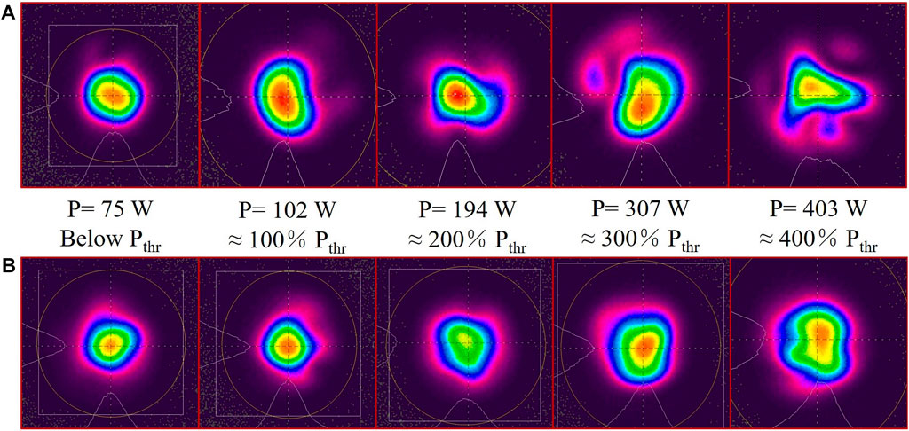
FIGURE 5. (A) Far-field spot distortions with power scaling in conventional amplifiers without the control system. (Particularly, the spots measured above the TMI threshold are not stable. Only one-frame photographs are presented here.) (B) Far-field spots measured at different powers in the amplifier using photonic lantern seeding with the controller is turned on. P, output power. Pthr, TMI threshold of this amplifier using conventional seeding.
Subsequently, the M2 factor of the output laser is also measured. For the amplifier seeded by conventional seed, when the output power is less than Pthr, M2 is 1.4–1.6; when it exceeds Pthr, the M2 factor varies from 2 to 3.7, and the beam quality seriously degrades. However, for the amplifier seeded by the photonic-lantern-based control system, the M2 factor is maintained at a low value (less than 2) during power scaling up to four times Pthr. Figure 6 shows the detailed results measured at 367 W. For the amplifier using photonic lantern seeding, as shown in Figure 6A, the focused location of the x direction is at ∼360 mm, while that of the y direction is at ∼355 mm. The inserted picture is the spot that is recorded at the Z location of 355 mm. Currently, the beam quality is measured with M2 values of 1.762 and 1.567 in the x and y directions, respectively. The beam quality value and the near-Gaussian spot profile prove that the amplifier is working at a near-diffraction-limited beam quality. However, for the amplifier using conventional seeding, as shown in Figure 6B, the M2 value is 2.646 and 2.503 in the x and y directions, respectively. Above all, the photonic-lantern-based mode control system significantly improves the beam quality of the fiber laser at a power above the original TMI threshold.
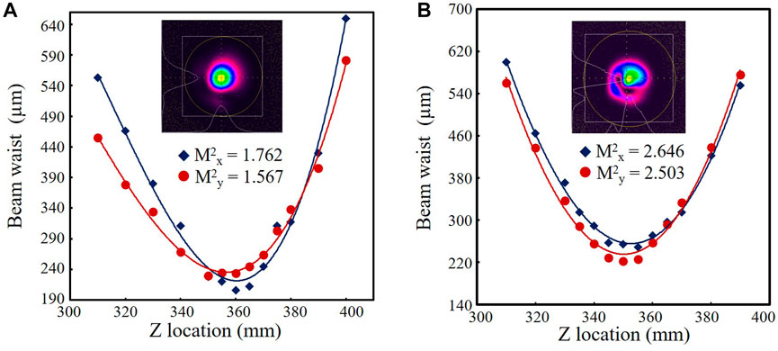
FIGURE 6. Beam quality measured at 367 W: (A) using photonic lantern seeding with the controller turned on; (B) using conventional seeding.
In this paper, we investigate the TMI mitigation capability of the photonic lantern seeding amplifier. We theoretically explain that exciting appropriate mode beatings as seed to form controllable MIPs can counteract the thermally-induced MIPs in active fiber and wash out the RIG. Experimentally, a stable beam profile and good beam quality are achieved above the TMI threshold. This strategy is adapted to a common step-index active fiber-assisted amplifier. Although we use the photonic lantern with a 30 µm output core to seed the 42/250 µm Yb-doped fiber amplifier, we still get a significant control effect and avoid the occurrence of TMI. Our further work will focus on the ability to keep good beam quality for higher power output in larger mode area fiber by matching the core diameter of the active fiber and the output fiber of the photonic lantern or by using photonic lanterns with more channels.
The original contributions presented in the study are included in the article/Supplementary Material; further inquiries can be directed to the corresponding authors.
YL and HX contributed to investigation. UL, ZJ, HX, ZC, MJ, and WL contributed to resources. YL contributed to writing original draft. ZJ, JC, HY, LD, DZ, JZ and QZ contributed to reviewing and editing. JZ and WL contributed to supervision. All authors contributed to the article and approved the submitted version.
This work was supported by the National Natural Science Foundation of China (12074432).
The authors declare that the research was conducted in the absence of any commercial or financial relationships that could be construed as a potential conflict of interest.
All claims expressed in this article are solely those of the authors and do not necessarily represent those of their affiliated organizations, or those of the publisher, the editors, and the reviewers. Any product that may be evaluated in this article, or claim that may be made by its manufacturer, is not guaranteed or endorsed by the publisher.
1. Wellmann F, Steinke M, Meylahn F, Bode N, Willke B, Overmeyer L, et al. High power, single-frequency, monolithic fiber amplifier for the next generation of gravitational wave detectors. Opt express (2019) 27(20):28523–33. doi:10.1364/oe.27.028523
2. Yang F, Ye Q, Pan Z, Chen D, Cai H, Qu R, et al. 100-mW linear polarization single-frequency all-fiber seed laser for coherent Doppler lidar application. Opt Commun (2012) 285(2):149–52. doi:10.1016/j.optcom.2011.09.030
3. Pham C, Duport F, Brenot R, Paret J-F, Garreau A, Gomez C, et al. Modulation of a high power semiconductor optical amplifier for free space communications. J Lightwave Technol (2020) 38(7):1836–43. doi:10.1109/jlt.2019.2959399
4. Rath W. Lasers for industrial production processing: Tailored tools with increasing flexibility. Lasers, sources, and related photonic devices. San Diego, CA: Optica Publishing Group (2012).
5. Zervas MN, Codemard CA. High power fiber lasers: A review. IEEE J Selected Top Quan Elect (2014) 20(5):219–41. doi:10.1109/jstqe.2014.2321279
6. Eidam T, Wirth C, Jauregui C, Stutzki F, Jansen F, Otto H-J, et al. Experimental observations of the threshold-like onset of mode instabilities in high power fiber amplifiers. Opt express (2011) 19(14):13218–24. doi:10.1364/oe.19.013218
7. Jauregui C, Stihler C, Limpert J. Transverse mode instability. Adv Opt Photon (2020) 12(2):429–84. doi:10.1364/aop.385184
8. Smith AV, Smith JJ. Mode instability in high power fiber amplifiers. Opt express (2011) 19(11):10180–92. doi:10.1364/oe.19.010180
9. Stutzki F, Jansen F, Otto H-J, Jauregui C, Limpert J, Tünnermann A. Designing advanced very-large-mode-area fibers for power scaling of fiber-laser systems. Optica (2014) 1(4):233–42. doi:10.1364/optica.1.000233
10. Matniyaz T, Bingham SP, Kalichevsky-Dong MT, Hawkins TW, Pulford B, Dong L. High-power single-frequency single-mode all-solid photonic bandgap fiber laser with kHz linewidth. Opt Lett (2022) 47(2):377–80. doi:10.1364/ol.449412
11. Hochheim S, Brockmüller E, Wessels P, Koponen J, Lowder T, Novotny S, et al. Single-frequency 336 W spliceless all-fiber amplifier based on a chirally-coupled-core fiber for the next generation of gravitational wave detectors. J Lightwave Technol (2022) 40(7):2136–43. doi:10.1109/jlt.2021.3133814
12. Naderi S, Dajani I, Grosek J, Madden T, Dinh T-N. Theoretical analysis of effect of pump and signal wavelengths on modal instabilities in Yb-doped fiber amplifiers. Proc SPIE (2014) 8964:89641W. doi:10.1117/12.2044143
13. Tao R, Su R, Ma P, Wang X, Zhou P. Suppressing mode instabilities by optimizing the fiber coiling methods. Laser Phys Lett (2017) 14(2):025101. doi:10.1088/1612-202x/aa4fbf
14. Stihler C, Jauregui C, Kholaif SE, Limpert J. Intensity noise as a driver for transverse mode instability in fiber amplifiers. PhotoniX (2020) 1(1):8. doi:10.1186/s43074-020-00008-8
15. Wu H, Li R, Xiao H, Huang L, Yang H, Leng J, et al. First demonstration of a bidirectional tandem-pumped high-brightness 8 kW level confined-doped fiber amplifier. J Lightwave Technol (2022) 40(16):5673–81. doi:10.1109/jlt.2022.3183381
16. Jauregui C, Stihler C, Tünnermann A, Limpert J. Pump-modulation-induced beam stabilization in high-power fiber laser systems above the mode instability threshold. Opt express (2018) 26(8):10691–704. doi:10.1364/oe.26.010691
17. Otto H-J, Jauregui C, Stutzki F, Jansen F, Limpert J, Tünnermann A. Controlling mode instabilities by dynamic mode excitation with an acousto-optic deflector. Opt express (2013) 21(14):17285–98. doi:10.1364/oe.21.017285
18. Montoya J, Aleshire C, Hwang C, Fontaine NK, Velázquez-Benítez A, Martz DH, et al. Photonic lantern adaptive spatial mode control in LMA fiber amplifiers. Opt express (2016) 24(4):3405–13. doi:10.1364/oe.24.003405
19. Montoya J, Hwang C, Martz D, Aleshire C, Fan TY, Ripin DJ. Photonic lantern kW-class fiber amplifier. Opt express (2017) 25(22):27543–50. doi:10.1364/oe.25.027543
20. Leon-Saval SG, Argyros A, Bland-Hawthorn J. Photonic lanterns. Photonic Lanterns Nanophotonics (2013) 2(5-6):429–40. doi:10.1515/nanoph-2013-0035
21. Lu Y, Liu W, Chen Z, Jiang M, Zhou Q, Zhang J, et al. Spatial mode control based on photonic lanterns. Opt express (2021) 29(25):41788–97. doi:10.1364/oe.440326
22. Lu Y, Chen Z, Liu W, Jiang M, Yang J, Zhou Q, et al. Stable single transverse mode excitation in 50 µm core fiber using a photonic-lantern-based adaptive control system. Opt express (2022) 30(13):22435–41. doi:10.1364/oe.458997
23. Lu Y, Jiang Z, Liu W, Zhou Q, Jiang M, Xie K. Orbital angular momentum mode generation system based on photonic lantern. J Opt (2019) 21(12):125702. doi:10.1088/2040-8986/ab52e6
24. Wiener N. The human use of human beings: Cybernetics and society. London, UK: Eyre and Spottiswoode (1954).
Keywords: mode instability, photonic lantern, adaptive control, mode beatings, fiber laser
Citation: Lu Y, Jiang Z, Xiao H, Chen Z, Jiang M, Chai J, Yang H, Ding L, Zhang D, Zhang J, Zhou Q and Liu W (2023) Mitigating mode instabilities by controllable mode beating excitation with a photonic lantern. Front. Phys. 11:1198092. doi: 10.3389/fphy.2023.1198092
Received: 31 March 2023; Accepted: 12 June 2023;
Published: 22 June 2023.
Edited by:
Rumao Tao, China Academy of Engineering Physics, ChinaReviewed by:
Yu Liu, China Academy of Engineering physics, ChinaCopyright © 2023 Lu, Jiang, Xiao, Chen, Jiang, Chai, Yang, Ding, Zhang, Zhang, Zhou and Liu. This is an open-access article distributed under the terms of the Creative Commons Attribution License (CC BY). The use, distribution or reproduction in other forums is permitted, provided the original author(s) and the copyright owner(s) are credited and that the original publication in this journal is cited, in accordance with accepted academic practice. No use, distribution or reproduction is permitted which does not comply with these terms.
*Correspondence: Zongfu Jiang, jiangzongfu7@163.com; Wenguang Liu, lwg.kevin@163.com
Disclaimer: All claims expressed in this article are solely those of the authors and do not necessarily represent those of their affiliated organizations, or those of the publisher, the editors and the reviewers. Any product that may be evaluated in this article or claim that may be made by its manufacturer is not guaranteed or endorsed by the publisher.
Research integrity at Frontiers
Learn more about the work of our research integrity team to safeguard the quality of each article we publish.