 Wei Wang1
- 1School of Computer Science and Technology, Harbin Institute of Technology, Weihai, China
- 2School of Space Science and Physics, Shandong University, Weihai, China
- 3Laboratory for Electromagnetic Detection (LEAD), Institute of Space Sciences, Shandong University, Weihai, China
We experimentally investigated the large area subwavelength cavity antenna with artificial permeability-negative metamaterials in the GHz region. It is demonstrated that this new type of planar metamaterials has better directivity and higher gain with the radiation source using the large non-uniform distributed patch array than using a uniform distributed patch array, where the current distribution of the radiation source satisfies the Chebyshev distribution. The experimental values agreed well with simulated results. This new metamaterial antenna has potential applications in weak microwave signal detection and radio observation fields.
Introduction
Since the negative refractive index is demonstrated experimentally in the microwave region, metamaterials have attracted wide attention owing to their unique ability to manipulate the propagation of electromagnetic waves (Smith, et al., 2004; Schurig, et al., 2006). According to the plus–minus sign of permeability and permittivity, metamaterials include single-negative and double-negative metamaterials, where the latter have the negative refractive index (Veselago, 1968), zero index, and hyperbolic metamaterials (Guo, et al., 2021; Guo, et al., 2022). Single-negative metamaterials consist of epsilon-negative metamaterials (ENMs) and mu-negative metamaterials (MNMs) in which the latter are also called the artificial magnetic conductors. Metamaterials have been used to fabricate many new excellent electromagnetic devices such as metamaterial antennas (Engheta, 2002; Enoch, et al., 2002; Zhou, et al., 2005; Wang, et al., 2006; Ourir, et al., 2006; Sun, et al., 2012).
The metamaterial antenna has the superiority compared with the conventional parabolic and microstrip antenna (Fan and Rahmat-Samii, 2003; Che, et al., 2013; Vaid and Mittal, 2015; Abu, et al., 2016). The physical mechanism in the metamaterial to modulate the electromagnetic waves is the local resonant coupling mechanism. An important property is that the unit cell of the metamaterial is much smaller than that of the wavelength, and the unit cell is insensitive to wavelength so that the size of the metamaterial may be less than the wavelength. However, the unit cell of the conventional antenna is comparable to the wavelength based on the multiple Bragg scattering mechanism so that the size of the antenna is usually larger than the wavelength. Therefore, the metamaterial antenna may have a smaller volume than the conventional antenna. For instance, the volume of a new zero-order resonant microstrip metamaterial antenna using the left-hand transmission line is nearly one-third of the conventional patch microstrip antenna so that it has a lighter weight (Fladie and Bernhard, 2006). Second, the metamaterial antenna may have the ultra-wide band. For example, the new antenna with a microstrip negative-index metamaterial has a relative bandwidth of almost ninety-four percent (Alhawari, et al., 2011). Third, the metamaterial antenna may have a better radiation performance by improving the matching condition (Enoch, et al., 2002). In particular, single-negative metamaterials are important to realize super-small antennas (Erentok and Ziolkowski, 2005; Fladie and Bernhard, 2006; Qiu, et al., 2017), where mu-negative metamaterials (MNMs) are used to fabricate subwavelength cavity planar antennas (Engheta, 2002; Enoch, et al., 2002; Zhou, et al., 2005; Wang, et al., 2006; Ourir, et al., 2006; Sun, et al., 2012; Lu, et al., 2019), since they can have a zero reflection phase similar to the perfect magnetic conductors (Lin, et al., 2016). For instance, the cavity thickness of the antennas using the MNMs only has one-sixtieth of the resonant wavelength so that the ultrathin directive antennas have the smaller volume (Lu, et al., 2019). Moreover, the main body of MNM antennas comprises the dielectric materials, and the metal only has a small proportion so that they have lighter weight than conventional antennas (Engheta, 2002; Enoch, et al., 2002; Zhou, et al., 2005; Wang, et al., 2006; Ourir, et al., 2006; Sun, et al., 2012; Lu, et al., 2019).
Nowadays, the metamaterial antennas mainly develop toward miniaturization, having ultra-thin thickness, less volume, and lighter weight. However, weak electromagnetic signal detection in some fields including radio astronomy and space spacecraft requires antennas with high directivity and gain, so the antennas need an ultra-large receiving area (Wolszczan and Frail, 1992; Meguro, et al., 2009; Iwai, et al., 2012; Tapping, 2013). It is found that the metamaterial antennas can realize high performance with a large receiving area but with subwavelength thickness and planar configuration (Lu, et al., 2019). Otherwise, the performance of the large-area planar metamaterial antenna nearly equals that of the conventional parabolic antenna with the same receiving area but with a larger volume (Lu, et al., 2019). In this study, we mainly investigated experimentally a kind of large receiving area planar metamaterial antenna in the L band where the radiation source is the large non-uniform distributed patch array.
The article is organized as follows. In the Theoretical Investigation of Ultra-Thin Large-Area Planar Metamaterial Antenna section, we investigated theoretically the ultra-thin large-area planar metamaterial antenna with the uniform distributed patch array as the radiation source. In the Experimental Investigation of Metamaterial Antennas With a Metallic Patch Array as the Radiation Source section, we studied theoretically and experimentally the performance of large-area planar metamaterial antennas with the non-uniform distributed patch array as the radiation source. Finally, the conclusions are given in the Conclusion section.
Theoretical Investigation of Ultra-Thin Large-Area Planar Metamaterial Antennas
In past research, many cavity antennas used the single weakly radiating antennas as the feed, where the changes in the transverse scale will inevitably affect the performance of antennas because of the influence of the boundary effect, material loss, and the effective radiation area of the radiation source. Therefore, there is an optimal aperture area for the radiation aperture of the antenna. When the optimal aperture area is exceeded and the transverse scale continues to increase, the boundary effect is offset by the effects of the reduction of the reflection coefficient and the increase of the loss so that the performance of the antenna will be degraded. On the other hand, it was theoretically found that the radiation source using a metal patch array instead of a single metal patch, where a surface source is used instead of a point source, realized the ultra-large radiation aperture of cavity antennas (Lu, et al., 2019). Based on the aforementioned information, an ultra-thin large radiation aperture planar MNM antenna, which has a subwavelength thickness, is investigated at 9.0 GHz in this study.
Considering the relation between the receiving area of the cavity antenna and the resonant frequency, we designed the metamaterial antenna in the L band, and the resonant frequency is 9.0 GHz. The schematic diagram of the metamaterial antenna is shown in Figure 1. The top layer is the partially reflective surface (PRS) where MNM units are periodically arranged on two surfaces of the dielectric plate (the Rogers 5880 RT high-frequency plate with εr = 2.20 and tanδ = 0.0009), whose thickness is 1.5 mm, the middle part is a subwavelength air cavity, and the bottom layer is the highly reflective backplane, whose top surface is the radiation source composed of the metal patch or metal patch array. In this study, the physical aperture of the square metamaterial antenna is designed as 250 × 250 mm.
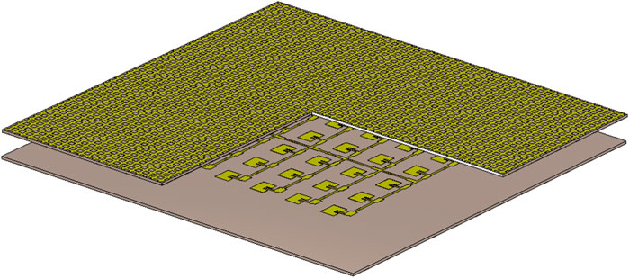
FIGURE 1. Schematic diagram of the metamaterial antenna.
Figure 2 shows the simulation results of the unit cell of the partially reflective surface (PRS). The schematic diagram of the PRS-MNM unit is given in Figure 2A where p (p = 5 mm) is the side length of the unit, l (l = 2.5 mm) is the width of the metallic cross wire that makes up the grid array, and w (w = 4.8 mm) is the side length of the square metallic sheet that makes up the patch array. The metal Cu is used with the electric conductivity 5.7 × 10⁷ S/m. Figures 2B, C show the simulated reflection amplitude and reflection phase of the MNM unit, respectively. Based on CST Microwave Studio, the reflection properties of the PRS-MNM unit can be simulated. At the resonant frequency 9.0 GHz, the reflection amplitude of the PRS-MNM unit has a minimal value, and its reflection phase is zero, as described in Figures 2B,C.
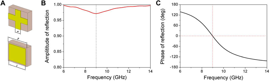
FIGURE 2. Simulation results of the MNM unit. (A) Schematic diagram of the MNM unit; (B) Simulated reflection amplitude. (C) Simulated reflection phase.
First, we engineered the MNM antenna with a single metal patch as the radiation source; its resonant frequency is 9.0 GHz, and its thickness is 10 mm. Simulated radiation properties of the MNM antenna are shown in Figure 3, where Figures 3A, B correspond to the H-plane and E-plane, respectively. The maximum realized gain is 21.8 dBi at 9.0 GHz, and the half power width is 5.0° (6.1°) in the H (E)-plane, but the sidelobe level is −7.3 dB (−7.3 dB) in the H (E)-plane. The physical mechanism originates from the aperture of the MNM antenna (250 mm × 250 mm) far larger than the optimal radiation area covered by only a single metallic patch as the radiation source.
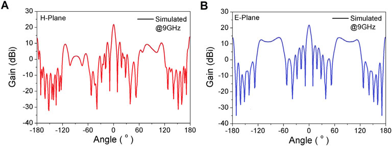
FIGURE 3. Simulated radiation properties of the MNM antenna with a single metallic patch as the radiation source at 9.0 GHz. (A) H-plane and (B) E-plane.
To realize the effective utilization of the radiation aperture, the radiation source with a 6 × 6 metallic patch array working at 9.0 GHz is designed, and the current on every radiation patch array is evenly distributed. All rectangular metallic patches are connected by a coaxial probe feed. The distance between adjacent metallic patches is 34 mm, which is larger than the resonant wavelength. The simulated radiation performances of this radiation source as an antenna are shown in Figure 4. The gain of the main lobe is 19.4 dBi, and the half-power width is 12.5° (11.9°), but the sidelobe level is −12.4 dB (−13.0 dB) in the H (E)-plane, as shown in Figures 4A, B, respectively. Because of the large distance between the metallic patches, the sidelobe of the radiation source patterns is relatively high. Moreover, the performance of the MNM antenna with a 6 × 6 metallic patch array as the radiation source at 9.0 GHz is given in Figure 5. The gain of the main lobe is 25.1 dBi, and the half-power width is 9.4° (8.6°), but the sidelobe level is −13.8 dB (−13.8 dB) in the H (E)-plane, as shown in Figures 5A,B, respectively.
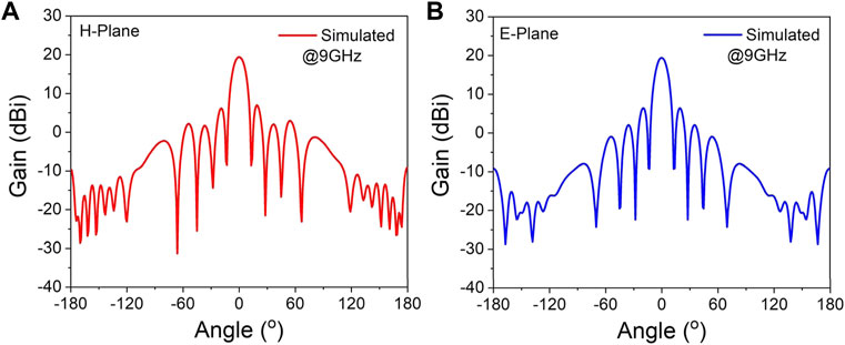
FIGURE 4. Simulated radiation properties of the radiation source composed of a 6 × 6 metallic patch array at 9.0 GHz, where the current on every radiation patch array is evenly distributed. (A) H-plane and (B) E-plane.

FIGURE 5. Simulated radiation properties of the MNM antenna with a 6 × 6 metal patch array as the radiation source at 9.0 GHz. (A) H-plane and (B) E-plane.
The radiation performances of four different antennas shown in Figures 3, 4, 5 at 9.0 GHz are shown in Table 1. Considering the physical size as an important parameter affecting the antenna’s performance, the last antenna is designed as shown in Table 1, which is composed of an 8 × 8 metallic patch array with uniform current strength distribution obtained by the function module “antenna magus” in CST Studio Suite and has the same aperture area with that of the MNM antenna, as shown in Figure 5. It can be seen that the MNM antenna using the patch array as a radiation source, as shown in Figure 5, improves the gain of the main lobe by about 3.3 dBi and the sidelobe level by about 6.5 dB (6.5 dB) in the H (E)-plane compared with the MNM antenna using a single patch as the radiation source, as shown in Figure 3. Otherwise, the MNM antenna shown in Figure 5 also has a better performance than the radiation source of an antenna composed of a 6 × 6 metallic patch array, as shown in Figure 4. Considering physical size as an important parameter affecting the antenna’s performance, the last antenna is designed as shown in Table 1. Moreover, the MNM antenna shown in Figure 5 has a better performance than the same-size antenna composed of an 8 × 8 uniform distributed patch array, where the gain of the former main lobe increases by about 4.2 dBi. However, the sidelobe of the MNM antenna in Figure 5 is still high, which cannot meet the needs of some ultra-low sidelobe applications.
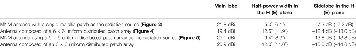
TABLE 1. Radiation performances of four different antennas.
In the next section, the work about the better performance of the MNM antenna with a lower sidelobe is investigated theoretically and experimentally.
Experimental Investigation of Metamaterial Antennas With a Metallic Patch Array as the Radiation Source
To reduce the sidelobe of the antenna, the radiation source with a metallic patch array was designed at 9.0 GHz, where the non-uniform feed form replaced the uniform feed form from the aforementioned designs. The structure is shown in Figure 6. The dielectric slab is the Rogers 5880 RT high-frequency plate with a thickness of 1.5 mm. One side of the dielectric slab is covered with a copper foil as a perfect reflector, and the center of the other side is an array with 6 × 6 rectangular metallic patches as the radiation source. To reduce the sidelobe level, the current distribution of each unit in the metallic patch array is designed according to the Chebyshev distribution method (Stutzman and Thiele, 2012), and the current distribution on the array is I1: I2: I3 = 1.00: 0.88: 0.66. Each rectangular metallic patch is connected by a metal microstrip feed network. In the metallic patch array, the distance between the patches is 34 mm, which is far less than the wavelength of 9.0 GHz. The excitation current is distributed from the feeding point to each rectangular metallic patch through the feed network. The performance of the radiation source at 9.0 GHz is shown in Figure 7, where the gain of the main lobe is 17.3 dBi at the operating frequency of 9.0 GHz. The half-power width is 14.7°, and the sidelobe level is −16.6 dB in the H-plane, as shown in Figure 7A. Figure 7B shows the half-power width 14.5° and sidelobe level −17.7 dB in the E-plane. Compared with the results in Figure 4, the sidelobe of the antenna is effectively reduced.
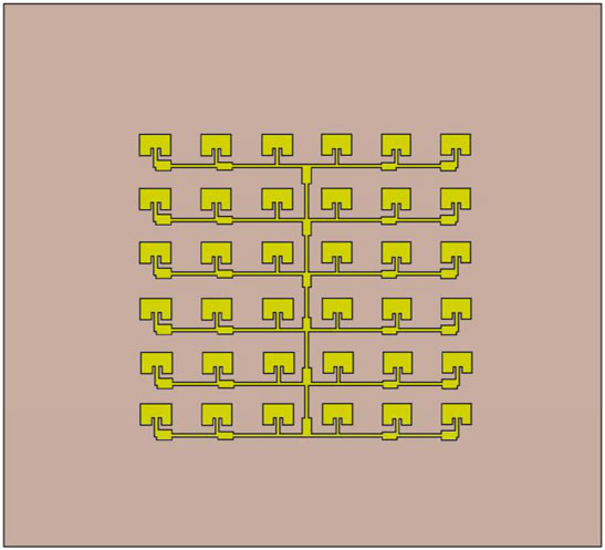
FIGURE 6. Diagram of the radiation source composed of a 6 × 6 metallic patch array with the Chebyshev current strength distribution.
FIGURE 7. Performance of the radiation source. (A) Simulated gain of the H-plane. (B) Simulated gain of the E-plane.
To analyze the performance of the MNM antenna with a non-uniform distributed patch array as the radiation source, the electric field intensity distributions at 9.0 GHz are simulated in the MNM antenna with a metallic patch and patch array as radiation sources, which are shown in Figures 8A, B, respectively. The parameters of the former and latter sources are the same as those in Figure 3 and Figure 6, respectively. It can be seen that the radiated electric fields from the radiation source with a metallic patch cannot effectively cover the whole antenna aperture as given in Figure 8A, which results in the weak performance of the antenna. However, the radiated electric fields from the latter radiation source have nearly complete coverage in the cavity of the antenna so that the latter antenna with the same large aperture has a better performance.
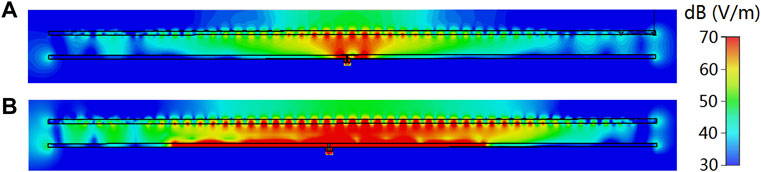
FIGURE 8. Intensity distribution of the electric field in the MNM antenna (cross section). (A) Single metallic patch as the radiation source of the antenna, which is same with that in Figure 3. (B) Metallic patch array as the radiation source which is shown in Figure 6.
According to the simulated results, the MNM antenna is engineered by the printed circuit board etching processing technique. The radiation source of the antenna uses a large non-uniform distributed patch array with 6 × 6 metallic patches, as shown in Figure 6. The antenna size is 250 mm × 250 mm × 10 mm, and the cavity thickness is only 7 mm, which is about 1/5 of the resonant wavelength. Figure 9A shows the image of the MNM antenna in the darkroom. Figure 9B shows that the simulated (experimental) return loss S11 is −24.3 dB (−18.2 dB), and the maximum realized gain is 25.0 dBi (23.9 dBi) at the resonant frequency of 9.0 GHz (8.93 GHz) described by the solid (dashed) line. Figures 9C, D show the radiation patterns in the H- and E-planes at the resonant frequency, where the simulated (experimental) half-power width is 11.2° (11.4°), and the sidelobe level is −22.1 dB (−24.1 dB) in the H-plane, and the simulated (experimental) half-power width is 10.9° (11.1°), and the sidelobe level is −25.8 dB (−22.8 dB) in the E-plane. The Keysight PNA N5224B 10 MHz–43.5 GHz vector network analyzer is used to measure the performance of the MNM antenna. The experimental results showed significant agreement with theoretical values. On the other hand, the small discrepancies between the theoretical and experimental results mainly originate from microstructure differences during the etching processes and refractive index discrepancies between the theoretical and experimental materials.
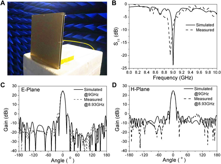
FIGURE 9. Performance of the MNM antenna, where the solid (dashed) line describes the simulated (experimental) results. (A) Antenna image in the darkroom. (B) Return loss S11. (C) Realized gain in the E-plane. (D) Realized gain in the H-plane.
The radiation performances of two different antennas shown in Figures 7, 9 are shown in Table 2, where the simulated and experimental results are summarized, respectively. It can be seen that the antenna shown in Figure 7 has a lower sidelobe than the antenna with a uniform distributed patch array in Figure 4, where the sidelobe of the former decreases by about 4.2 dB (4.3 dB) in the H (E)-plane. Otherwise, the experimental results show that the main lobe gain of the MNM antenna in Figure 9 increases by about 5.4 dBi, and its side-lobe level increases by about 7.5 dB (5.1 dB) in the H (E)-plane than those of the antenna in Figure 7. As a result, an ultra-thin planar MNM antenna with a non-uniform distributed patch array as the radiation source is realized where it has a large radiation aperture and good performance.
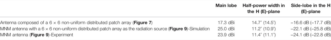
TABLE 2. Radiation performances of two different antennas.
Conclusion
Based on artificial magnetic conductor materials, a kind of new planar subwavelength metamaterial antenna with good performance is realized. Compared with the traditional antenna, the cavity thickness of the antenna is only 1/5 of the resonant wavelength. Furthermore, it has a high gain, large radiation aperture, and good directivity. Such a metamaterial antenna has potential applications in large microwave communication or radio observation equipment.
Data Availability Statement
The original contributions presented in the study are included in the article/Supplementary Material, further inquiries can be directed to the corresponding authors.
Author Contributions
GD and GL designed the research and analyzed the data. GL, WW, CD, XZ, JL and FL performed the research and analyzed the data. GD, GL and WW wrote the manuscript and contributed to the revisions.
Funding
This work was supported by the Natural Science Foundation of Shandong Province (Nos. ZR2019MA055 and ZR2020QA071) and the National Natural Science Foundation of China (No. 12047536).
Conflict of Interest
The authors declare that the research was conducted in the absence of any commercial or financial relationships that could be construed as a potential conflict of interest.
Publisher’s Note
All claims expressed in this article are solely those of the authors and do not necessarily represent those of their affiliated organizations, or those of the publisher, the editors, and the reviewers. Any product that may be evaluated in this article, or claim that may be made by its manufacturer, is not guaranteed or endorsed by the publisher.
References
Abu, M., Muhamad, M., Zakaria, Z., and Hasan, H. (2016). “Millimeter-Wave Parasitic Amc Patches on the Array Antenna,” in 2016 International Conference on Computer and Communication Engineering (Kuala Lumpur: ICCCE), 19–24. doi:10.1109/ICCCE.2016.18
Alhawari, A. R. H., Ismail, A., Mahdi, M. A., and Abdullah, R. S. A. R. (2011). Miniaturized Ultra-wideband Antenna Using Microstrip Negative Index Metamaterial. Electromagnetics 31, 404–418. doi:10.1080/02726343.2011.590961
Che, W., Yang, W., and Wang, H. (2013). “Investigations of Amc and its Applications for Performance Enhancement of Planar Antenna Arrays,” in IEEE International Workshop on Electromagnetics. Kowloon, 23–27. doi:10.1109/iWEM.2013.6888760
Engheta, N. (2002). An Idea for Thin Subwavelength Cavity Resonators Using Metamaterials with Negative Permittivity and Permeability. Antennas Wirel. Propag. Lett. 1, 10–13. doi:10.1109/lawp.2002.802576
Enoch, S., Tayeb, G., Sabouroux, P., Guérin, N., and Vincent, P. (2002). A Metamaterial for Directive Emission. Phys. Rev. Lett. 89, 213902. doi:10.1103/PhysRevLett.89.213902
Erentok, A., and Ziolkowski, R. W. (2005). “Dipole Antennas Enclosed in Double Negative (DNG) and Single-Negative (SNG) Nested Spheres: Efficient Electrically Small Antennas,” in IEEE Antennas and Propagation Society International Symposium. Washington, DC, 252–255. doi:10.1109/APS.2005.1551535
Fan, Y., and Rahmat-Samii, Y. (2003). Microstrip Antennas Integrated with Electromagnetic Band-Gap (Ebg) Structures: A Low Mutual Coupling Design for Array Applications. IEEE Trans. Antennas Propagat. 51, 2936–2946. doi:10.1109/tap.2003.817983
Fladie, J. A., and Bernhard, J. T. (2006). On the Radiation Characteristics of Right- and Left-Handed Microstrip Patch Antenna Designs. Antennas Wirel. Propag. Lett. 5, 563–565. doi:10.1109/lawp.2006.889556
Guo, Z., Jiang, H., and Chen, H. (2022). Zero-index and Hyperbolic Metacavities: Fundamentals and Applications. J. Phys. D: Appl. Phys. 55 (8), 083001. doi:10.1088/1361-6463/ac2e89
Guo, Z., Long, Y., Jiang, H., Ren, J., and Chen, H. (2021). Anomalous Unidirectional Excitation of High-K Hyperbolic Modes Using All-Electric Metasources. Adv. Photon. 3, 036001. doi:10.1117/1.AP.3.3.036001
Iwai, K., Tsuchiya, F., Morioka, A., and Misawa, H. (2012). Iprt/Amateras: A New Metric Spectrum Observation System for Solar Radio Bursts. Sol. Phys. 277, 447–457. doi:10.1007/s11207-011-9919-y
Lin, L., Jiang, Z. H., Ma, D., Yun, S., Liu, Z., Werner, D. H., et al. (2016). Dielectric Nanoresonator Based Lossless Optical Perfect Magnetic Mirror with Near-Zero Reflection Phase. Appl. Phys. Lett. 108, 171902. doi:10.1063/1.4947274
Lu, G., Wang, W., Yan, F., Diao, C., Zhou, X., Wu, Z., et al. (2019). Large Area Subwavelength Cavity Antenna with Planar Metamaterials. AIP Adv. 9, 025032. doi:10.1063/1.5089666
Meguro, A., Shintate, K., Usui, M., and Tsujihata, A. (2009). In-Orbit Deployment Characteristics of Large Deployable Antenna Reflector Onboard Engineering Test Satellite Viii. Acta Astronautica 65, 1306–1316. doi:10.1016/j.actaastro.2009.03.052
Ourir, A., de Lustrac, A., and Lourtioz, J.-M. (2006). All-metamaterial-based Subwavelength Cavities (λ∕60) for Ultrathin Directive Antennas. Appl. Phys. Lett. 88, 084103. doi:10.1063/1.2172740
Qiu, Y., Peng, L., Jiang, X., Sun, Z., and Tang, S. (2017). Ultra-Small Single-Negative Metamaterial Insulator for Mutual Coupling Reduction of High-Profile Monopole Antenna Array. Pier C 72, 197–205. doi:10.2528/pierc16100803
Schurig, D., Mock, J. J., Justice, B. J., Cummer, S. A., Pendry, J. B., Starr, A. F., et al. (2006). Metamaterial Electromagnetic Cloak at Microwave Frequencies. Science 314, 977–980. doi:10.1126/science.1133628
Smith, D. R., Pendry, J. B., and Wiltshire, M. C. K. (2004). Metamaterials and Negative Refractive Index. Science 305, 788–792. doi:10.1126/science.1096796
Stutzman, W. L., and Thiele, G. A. (2012). Antenna Theory and Design. 3rd Edition. Hoboken, NJ: John Wiley & Sons.
Sun, Y., Chen, Z. N., Zhang, Y., Chen, H., and See, T. S. P. (2012). Subwavelength Substrate-Integrated Fabry-Pérot Cavity Antennas Using Artificial Magnetic Conductor. IEEE Trans. Antennas Propagat. 60, 30–35. doi:10.1109/tap.2011.2167902
Tapping, K. F. (2013). The 10.7 Cm Solar Radio Flux (F10.7). Space Weather 11, 394–406. doi:10.1002/swe.20064
Vaid, S., and Mittal, A. (2015). High Gain Planar Resonant Cavity Antennas Based on Metamaterial and Frequency Selective Surfaces. AEU - Int. J. Electron. Commun. 69, 1387–1392. doi:10.1016/j.aeue.2015.05.014
Veselago, V. G. (1968). The Electrodynamics of Substances with Simultaneously Negative Values of ε and μ. Sov. Phys. Usp. 10, 509–514. doi:10.1070/PU1968v010n04ABEH003699
Wang, S., Feresidis, A. P., Goussetis, G., and Vardaxoglou, J. C. (2006). High-Gain Subwavelength Resonant Cavity Antennas Based on Metamaterial Ground Planes. IEE Proc. Microw. Antennas Propag. 153, 1–6. doi:10.1049/ip-map:20050090
Wolszczan, A., and Frail, D. A. (1992). A Planetary System Around the Millisecond Pulsar Psr1257 + 12. Nature 355, 145–147. doi:10.1038/355145a0
Keywords: metamaterial, antenna, subwavelength cavity, microwave, artificial magnetic conductor
Citation: Wang W, Lu G, Diao C, Zhou X, Li J, Liu F and Du G (2022) Experimental Investigation of Large Area Subwavelength Cavity Antennas With Planar Metamaterials. Front. Mater. 9:865128. doi: 10.3389/fmats.2022.865128
Received: 29 January 2022; Accepted: 14 March 2022;
Published: 07 April 2022.
Edited by:
Zhiwei Guo, Tongji University, ChinaReviewed by:
Wang Shen-Yun, Nanjing University of Information Science and Technology, ChinaHaitao Jiang, Tongji University, China
Copyright © 2022 Wang, Lu, Diao, Zhou, Li, Liu and Du. This is an open-access article distributed under the terms of the Creative Commons Attribution License (CC BY). The use, distribution or reproduction in other forums is permitted, provided the original author(s) and the copyright owner(s) are credited and that the original publication in this journal is cited, in accordance with accepted academic practice. No use, distribution or reproduction is permitted which does not comply with these terms.
*Correspondence: Guang Lu, guanglu@sdu.edu.cn; Guiqiang Du, dgqql@sdu.edu.cn