 Haixia Liu1
 Qi Jia
95% of researchers rate our articles as excellent or good
Learn more about the work of our research integrity team to safeguard the quality of each article we publish.
Find out more
ORIGINAL RESEARCH article
Front. Mater. , 10 May 2022
Sec. Metamaterials
Volume 9 - 2022 | https://doi.org/10.3389/fmats.2022.908058
This article is part of the Research Topic Acoustic and Mechanical Metamaterials for Various Applications View all 13 articles
In this paper, a novel radial seismic metamaterial (LRSM) based on layering theory is proposed. Compared with traditional seismic metamaterials, the structure of LRSM is a periodic array of multi-layer rings distributed along the radial direction. By using the finite element method, the dispersion relationship and displacement vector field of LRSM with different layers are studied, and the influence of structural geometric parameters and circumferential continuity on the band gap characteristics of LRSM is discussed. The frequency domain analysis of finite periodic structure and the three-dimensional transient wave propagation analysis are carried out. The results show that the LRSM has ultra-low frequency broadband characteristics, which is produced by the coupling between the local resonance of the LRSM and the surface wave mode. Comparing three LRSMs with different layers, the initial frequency and bandwidth do not change monotonically with the increase of the number of layers. There is an optimal bandgap characteristic in two layers, and the relative bandwidth can reach 83.9%. The increase of the number causes the change of the structural stiffness, which is caused by the change of the local resonance strength. The position and width of the band gap in the LRSM are very sensitive to the height of the structure. The increase of the height of the LRSM can move the first band gap to the low frequency, and the total bandwidth increases, which is mainly caused by the increase of the equivalent mass of the system with the increase of the height of the structure. Further, it is verified that LRSM can effectively attenuate seismic surface waves of 0.1–20 Hz, and its maximum amplitude attenuation can exceed 85%. The novel periodic structure proposed in this paper can provide new options for the fields of earthquake and low-frequency vibration reduction.
Earthquakes are violent events caused by the movement of the earth’s medium. According to statistics, millions of earthquakes occur every year on the earth, among which there are thousands of earthquakes with magnitudes above five (Reitherman, 2012; Wilson et al., 2014). Earthquakes propagate in the form of elastic waves radiating from the epicenter to the surrounding area. When they meet the earth’s surface, they will generate surface waves that only propagate along the earth’s surface (Dobrin and Savit, 1960; Telford et al., 1990). Its vibration can cause the resonance of urban buildings, especially high-rise buildings, and cause strong damage to the buildings (Lim and Reddy, 2019; Liu et al., 2020; Zeng et al., 2020). Recently developed metamaterials offer new ways to control seismic surface waves.
Metamaterials are periodic composite materials composed of subwavelength units, which have physical properties not found in natural materials, such as negative mass density (Wang et al., 2015; Wang et al., 2021) double negative modulus (Li and Chan, 2004), etc., which is an important research topic. The bandgap characteristics of metamaterials with wave regulation, the acoustic/elastic waves within the bandgap range are effectively attenuated and reflected, providing new ideas for shock absorption technology. Designing seismic metamaterials based on metamaterial theory has become an active research field (Chen and Wang, 2014; Krödel et al., 2015; Achaoui et al., 2016). S. Brûlé et al. (2014) periodically distributed holes in homogeneous soil to form a seismic metamaterial with soil as matrix and vertical holes as scatterers. Through numerical simulation and experimental verification, it was proved that its structure has a high effect on the center frequency. The 50 Hz seismic wave has obvious blocking effect; Miniaci et al. (2016) proposed a super-large two-dimensional seismic metamaterial, which can realize the isolation and shielding of 4.1–5.5 Hz seismic surface waves by burying periodic square steel piles in the soil.; Palermo et al. (2016) designed a seismic metamaterial with periodic arrangement of special resonators. Since each resonator in the array is designed to present a different eigenfrequency, it can effectively block seismic surface waves with a frequency of 4.9–7.5 Hz. Zeng et al. (Du et al., 2018) designed seismic metamaterials to expand the wide band gap based on the “fraction theory” (Norris et al., 2008); Sang-Hong Kim et al. (Kim and Das, 2012) designed a seismic wave with a cylindrical shell waveguide composed of multiple Holmhertz resonators Attenuator, which can block the transmission of seismic wave energy in a wide frequency range. Bogdan Ungureanu et al. (Ungureanu et al., 2015) designed a negative modulus metamaterial unit cell, which can effectively protect target buildings in a wide frequency range. Achaoui et al. (2017) proposed that the columnar seismic metamaterial is fixed on the bedrock, which can isolate seismic waves below 20 Hz. Although researchers at home and abroad have achieved a lot of research results on the low-frequency broadband characteristics of surface waves, the research work on ultra-low frequency (0.1–5 Hz) seismic surface waves is still very limited, and the current space of seismic metamaterials Periodicity is defined by lattice vectors in Cartesian coordinates.
Torrent et al. (Torrent and Sánchez-Dehesa, 2009; Torrent and Sánchez-Dehesa, 2010a; Torrent and Sánchez-Dehesa, 2010b) first proposed radial metamaterials whose structures are periodically distributed in the radial direction. The existence of the acoustic band gap was verified through numerical and experimental studies. Li et al. (2014) combined elastic wave equation and finite element theory, proposed radial elastic metamaterials, studied the band gap characteristics of elastic waves in radial metamaterials, and proved that radial elastic metamaterials can effectively block elastic waves in the band gap. Researchers have found that radial metamaterials exhibit special omnidirectional wave shielding properties (Carbonell et al., 2011; Xu et al., 2012; Gao et al., 2016b; Shi et al., 2016), and have ultra-low frequency broadband characteristics (Ma et al., 2014; Shu et al., 2015; Gao et al., 2017; Jiang and He, 2017; An et al., 2018). Therefore, radial periodic structures are introduced into seismic metamaterials to study the propagation characteristics of seismic surface waves.
Furthermore, layered theory (Pennec et al., 2010; Elford et al., 2011; Neto et al., 2015) has been used to generate multi-order resonances to widen the acoustic/elastic wave band gap in metamaterials. In this paper, a layered radial seismic metamaterial (LRSM) is proposed, and its band gap characteristics are calculated by the finite element method. The effects of geometric parameters and the internal circumferential continuity of the structure on the shielding properties of radial seismic metamaterials are studied. Finally, the frequency response analysis and full-scale 3D transient wave propagation simulation are used to verify. In this paper, a high-performance, low-cost seismic metamaterial for engineering applications is realized by applying the periodic composite of steel and rigid foam, a common material in construction.
As shown in Figure 1, the proposed model in this paper is a radial periodic array with layered structural features on the surface of a semi-infinite base, as shown in Figure 1A. The protection building is located in the center of the LRSM, and the schematic diagram of its array distribution cross-section is shown in Figure 1B.
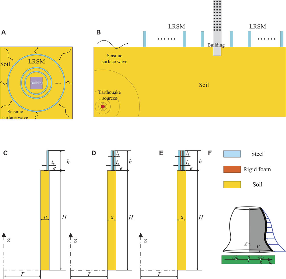
FIGURE 1. Radial seismic metamaterials: (A) and (B) radial seismic metamaterials surrounding important buildings; (C) LRSM-1; (D) LRSM-2; (E) LRSM-3; (F) the formation mode of the radial seismic metamaterials and diagram of BZ wave vector (Gamma-R) in reciprocal space. The blue, orange and yellow represent steel, hard foam and soil, respectively.
In this paper, three radial seismic metamaterials (LRSMs) with different layers are studied, as shown in Figure 1C–E, respectively, and their structural radius parameter r remains unchanged. According to the survey data of different earthquakes, it is the most difficult to formulate protective measures for the long waves with the frequency distribution of seismic surface waves in the range of 0.1–20 Hz, and the corresponding wavelengths vary from several hundred meters to several meters (Zeng et al., 2019). Therefore, the lattice constant a = 2.5 m, which is much smaller than the wavelength of seismic waves (Du et al., 2018). The height of the LRSM is h = 4a. The depth of the basement is H = 20a to ensure that it is sufficient to separate body and surface waves in seismic waves. Figure 1C shows a radial seismic metamaterial unit cell composed of a single-layer steel ring, which is defined as LRSM-1, where the distance e = 0.1a between the outer diameter of the steel ring and the cell boundary, and the steel ring thickness ts = 0.2a. Figure 1D shows the second radial seismic metamaterial unit cell, which is defined as LRSM-2, which is based on the single-layer steel ring structure, which is a foam ring with a thickness of tf = 0.1a and a steel ring with a thickness of ts in turn in the radial direction. Figure 1E shows the third radial seismic metamaterial unit cell. On the basis of LRSM-2, a foam ring of thickness tf and a steel ring of thickness ts are successively nested in the radial direction, which is defined as LRSM-3. By periodically repeating the LRSM unit cell along the r-direction and rotating around the Z-axis, an infinite system of LRSMs is formed, as shown in Figure 1F. In order to consider the engineering application of the structure, conventional building materials are chosen as the raw material of LRSM, such as steel and rigid foam, and the material of the base is soil (Zeng et al., 2018). In this paper, the material is assumed to be linear elastic, homogeneous and isotropic (Du et al., 2017). The material properties of the unit cell and substrate are shown in Table 1. The following material parameters are common parameters in engineering applications.
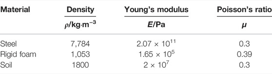
TABLE 1. Material properties of LRSM cell and substrate.
Due to the particularity of the structure, the two-dimensional axisymmetric finite element method based on cylindrical coordinate system is used to study the band gap characteristics of the metamaterial structure. The elastic wave equation in cylindrical coordinate system is established to calculate the dispersion relation curve in infinite system. Where u, v, w are the displacement components of the cylindrical coordinate system, ρ is the density, t is the time, λ and μ are the elastic wave constants of the material, r, θ, z are the coordinate components of the cylindrical coordinate system.
The volume strain θt and rotational components (w′r, w′θ, w′z) are defined as:
Since the periodic structure of the lattice unit is infinite along the radial direction, according to Bloch’s theorem, only a single lattice unit is considered. Its lattice boundary condition equation is:
where r is the radial position, a is the lattice constant, and kr is the component of the Bloch wave vector Kr in the radial direction.
By Eq. 3, applying a periodic boundary condition on r, the dispersion relation curve of the radial metamaterial structure can be obtained by sweeping the Bloch wave vector Kr across the boundary of the first irreducible Brillouin zone.
According to finite element theory (Li et al., 2014), Eq. 1a can be transformed into a generalized eigenvalue equation with discrete form:
where K is the stiffness matrix of the metamaterial structure, M is the mass matrix of the metamaterial structure, and u is the eigenvector.
After obtaining the finite element generalized eigenequation Eq. 4, by giving a set of Bloch wave vectors Kr, the eigenfrequency ω of each order of a single lattice unit is calculated under the condition of the wave vector, and substituted into the finite element equation, namely Eigenvectors of all orders
The dispersion curves of three different LRSMs are shown in Figures 2A, 3A, 4A. In the dispersion graph, the sound cone surrounded by the gray area is important for separating surface and bulk waves, all bulk modes are located outside the sound cone, and surface wave modes are inside the sound cone (Colombi et al., 2016). In this paper, the relative band gap bandwidth (NRBW), which is the ratio of the total band gap width to the acoustic cone height (Zeng et al., 2018), is introduced to evaluate the LRSM surface wave band gap characteristics. For LRSM-1, it can be seen from Figure 2A that below 12 Hz, LRSM-1 has only one energy band curve, the complete band gap of surface wave is 3.12–11.96 Hz, and its NRBW is 73.9%, which is much higher than that of Miniaci (Miniaci et al., 2016), Palermo (Palermo et al., 2016) and Colombi (Colombi et al., 2016), etc. (NRBW is less than 20%).
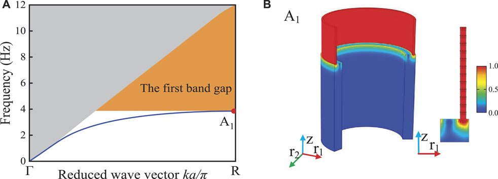
FIGURE 2. Dispersion curve, eigenmode and displacement vector field of LRSM-1: (A) dispersion curves; (B) eigenmode and displacement vector field at point A1. Colors represent the displacement amplitude, and black arrows represent the displacement direction.
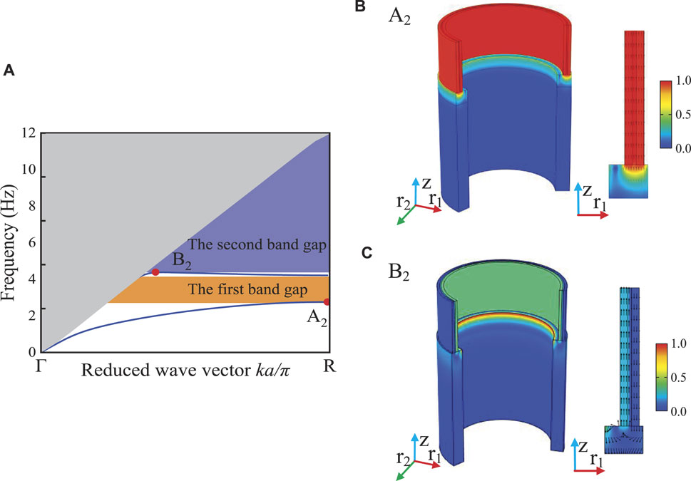
FIGURE 3. Dispersion curve, eigenmode and displacement vector field of LRSM-2: (A) dispersion curves; eigenmode and displacement vector field at (B) point A2 and (C) point B2. Colors represent the displacement amplitude, and black arrows represent the displacement direction.
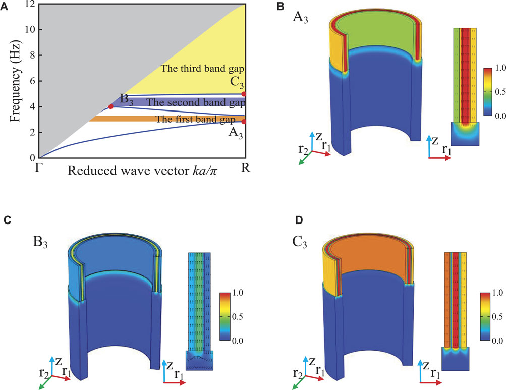
FIGURE 4. Dispersion curve, eigenmode and displacement vector field of LRSM-3: (A) dispersion curves; eigenmode and displacement vector field at (B) point A3, (C) point B3 and (D) point C3. Colors represent the displacement amplitude, and black arrows represent the displacement direction.
In order to study the generation mechanism of LRSM-1 ultra-low frequency broadband, the eigenmodes and displacement vector fields at point A1 in the single dispersion curve of Figure 2A are calculated, as shown in Figure 2B. The black arrows represent the direction of the vibrational displacement, and the color represents the magnitude of the vibrational displacement. At point A1, it appears as the coupling mode of the in-phase vibration of the steel ring along the axial direction and the Rayleigh wave mode. The elastic stiffness of the structure is provided by the soil base, and its local vibration mode can be equivalent to a typical “mass-spring” system. The frequency of the resonance bandgap can be determined by the natural frequency of the local resonance and can be evaluated in terms of the equivalent mass that provides the mass part (LRSM) and the equivalent stiffness that provides the elastic part (soil base) for this vibration mode:
where Ke is the equivalent stiffness of the system and Me is the equivalent mass of the system.
It can be seen from Eq. 5 that due to the circumferential continuity of LRSM-1, its equivalent mass Me is much higher than its equivalent stiffness Ke, so the initial frequency of the structural resonance band gap is in the ultra-low frequency range, and due to the structural sound The cone height is fixed (Zeng et al., 2018), so that the LRSM-1 exhibits very low frequency broadband characteristics.
The dispersion curve of LRSM-2 is shown in Figure 2B, it has two energy band curves below 12 Hz, and produces two complete band gaps, namely 2.72–4.21 Hz and 4.38–11.96 Hz, and its NRBW is 75.5%. Compared with LRSM-1, the onset frequency of the first band gap is shifted down and a new resonance band appears at 4.38 Hz. Further, by calculating the eigenmodes and displacement vector fields of the special points A2 and B2 on the two energy band curves, as shown in Figures 3B,C, respectively, to study the physical mechanism of the change of the band gap structure. The vibration mode of point A2, similar to point A1, is the overall axial in-phase vibration of the multilayer structure, but the initial frequency of the first band gap is lower than that of point A1 due to the increase of the equivalent mass of the structure. The vibration mode at point B2 is shown as the axial anti-phase resonance of the two-layer steel ring, and the energy is concentrated in the inner steel ring layer.
The dispersion curve of LRSM-3 is shown in Figure 4A. It can be seen from the figure that there are three energy bands below 12 Hz, forming three complete band gaps, which are 2.84–3.32 Hz, 4.02–4.85 Hz, and 4.98–11.96 Hz respectively., its NRBW is 69.3%. Compared with LRSM-2, the starting frequency of the first band gap is increased, while the starting frequency of the second band gap is decreased, and a new resonance band appears around 5 Hz. Figure 4B,C,D are the eigenmodes and displacement vector fields of the special points A3, B3 and C3 of the dispersion curve, respectively. At point A3, although the multi-layer structure exhibits axial in-phase vibration as a whole, its amplitudes are different, which is manifested as different amplitude resonance in the same phase of the structure’s axial direction. The vibration energy is concentrated in the foam ring and steel ring in the middle, and the vibrational energy of the inner steel ring is the smallest, which is manifested as a decrease in the onset frequency of the first bandgap of LRSM-3. This is caused by the coupling resonance of the three-layer steel rings with different amplitudes due to the small stiffness of the foam rings on both sides of the middle steel ring. In order to further study the effect of the foam ring on the initial frequency of the first band gap of LRSM-3, the vibration modes of point A3 under different elastic modulus Ef states of the foam ring were calculated, as shown in Figure 5. As the elastic modulus Ef of the rigid foam ring decreases, the stiffness provided by the foam ring in the middle decreases, and the structure gradually changes from the overall axial resonance with the same amplitude to the coupled resonance with different amplitudes for each layer. The eigenmodes and displacement vector field of point B3 are shown in Figure 4C, which is similar to the eigenmodes of point B2, showing the anti-phase resonance of the inner two-layer steel ring and the outer steel ring. Figure 4D shows the eigenmode and displacement vector field at point C3. At point C3, a more complex axial in-phase coupling resonance is presented, and the vibration energy is mainly concentrated in the middle steel ring. Therefore, as the number of layers in the system increases, more and more complex surface wave vibration modes will appear, resulting in new energy bands. As the number of layers of steel rings increases, the initial frequency of LRSM does not decrease monotonically, and the total bandwidth does not increase monotonically. The intensity of the resonance changes, so that the structure exhibits a complex axial resonance mode. When LRSM-2, it presents the lowest onset frequency and the largest bandwidth of the band gap, which is different from the traditional layered seismic metamaterial (MSM) (Zeng et al., 2020).
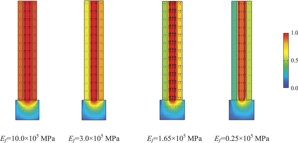
FIGURE 5. Eigenmode and displacement vector field at point A3 in rigid foam ring with different elastic modulus Ef.
In conclusion, all three LRSM structures exhibit ultra-low frequency broadband characteristics, and the vibration mode in the low frequency band is only the axial vibration mode, which is caused by the unique large-mass annular structure of LRSM. The LRSM barrier is fixed on the soil surface, and the unit cell is a large-mass annular structure, not only the resonance frequency is ultra-low frequency, but also the annular structure fixed on the soil surface has special stability in the circumferential direction (Budiansky and Hutchinson, 1966), so the LRSM band structure It is simple, and only presents as an axial vibration mode, showing ultra-low frequency broadband characteristics.
The ultra-low frequency broadband characteristics of LRSM are caused by the local resonance coupling between Rayleigh mode and the LRSM structure. The structural parameters of LRSM have an important influence on the ultra-low frequency broadband characteristics. In this section, the influence of geometric parameters on the complete band gap is analyzed while keeping other parameters unchanged. This study was conducted on LRSM-2.
Figure 6 shows the effect of the steel ring thickness ts on the change of the band gap characteristics. In Figure 6A, as ts/a increases, the first full bandgap bandwidth gradually decreases, and the second bandgap bandwidth increases and moves to low frequencies. The first band gap of LRSM-2 is caused by the overall axial in-phase resonance of the structure, and the change of the thickness ts of the steel ring has a great influence on the equivalent mass and equivalent stiffness of the structure. When ts/a < 0.2, the increase of the resonance mass in the structure will be dominant, with the increase of the parameter ts/a, the equivalent mass increases, and the initial frequency of the first band gap moves rapidly to the low frequency; when ts/a = 0.2, the change of the steel ring thickness ts makes the equivalent mass of the structure and the equivalent stiffness increase close to each other. Therefore, the initial frequency of the first band gap remains basically unchanged, and the cut-off frequency moves to the low frequency. The band gap is then narrowed. For the second band gap, with the increase of ts/a, the axial resonance coupling between the structure and the soil base gradually increases, and the initial frequency gradually shifts to the low frequency. Since the height of the sound cone of the structure is fixed, its bandwidth increases and shifts to low frequencies. With the increase of ts/a, the NRBW shows a trend of first increasing and then decreasing. When ts/a = 0.2a, the NRBW is the largest, reaching to 75.8% (as shown in Figure 6B).
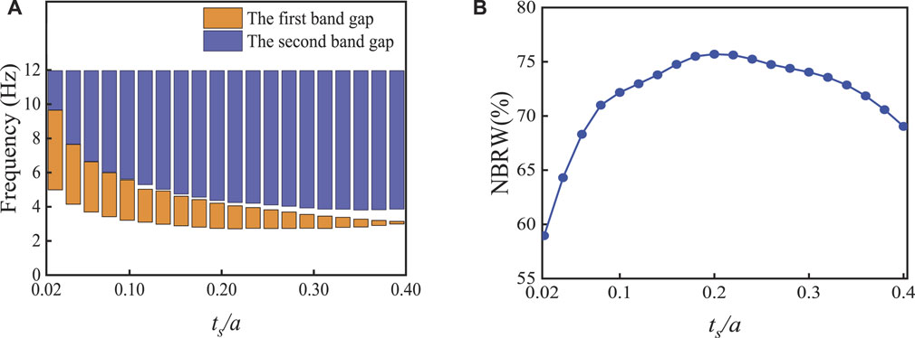
FIGURE 6. Relationship between bandgaps characteristics and parameter ratio ts/a: (A) the upper and lower frequency bounds of bandgaps; (B) the relative band width of bandgap (NRBW).
Figure 7 shows the effect of the rigid foam ring thickness tf of LRSM-2 on the band gap characteristics (the position parameter e remains unchanged). It can be seen from Figure 7A that with the increase of tf, the center frequencies of the first and second band gaps are both moved down, and the bandwidth is gradually narrowed. When tf = 0.125a, the third band gap begins to appear. Figure 7B shows the effect of rigid foam ring thickness tf on the NRBW. It can be seen from the figure that with the increase of rigid foam ring thickness tf, the NRBW shows an overall decreasing trend. When tf/a = 0.01a, the NRBW achieves the optimal value of 78.3%.
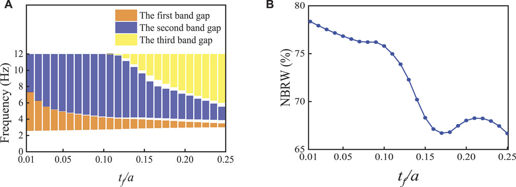
FIGURE 7. Relationship between bandgaps characteristics and parameter ratio tf/a: (A) the upper and lower frequency bounds of bandgaps; (B) the relative band width of bandgap (NRBW).
Figures 8A,B show the eigenmode and displacement vector field of band structure and special points when tf = 0.125a, respectively. By comparing Figure 3B, it can be found that the vibration mode of point A2 in Figure 3 is consistent with that of point A4 in Figure 8, both of which are axial in-phase local resonances, and the resonance intensity is similar, indicating that the increase in the thickness of hard foam ring tf has little effect on the axial in-phase resonance mode of the system, so the initial frequency of the first band gap remains basically unchanged. The mode shape of point B4 in Figure 8 is stronger than that of point B2 in Figure 3, which indicates that with the increase of the thickness tf of the rigid foam ring, the local resonance effect is enhanced, resulting in the onset of the second band gap. The initial frequency is shifted to lower frequencies. In addition, with the further increase of the thickness tf of the rigid foam ring, the system stiffness of the resonant structure decreases, which makes the structure appear a new local resonance mode, that is, the anti-phase resonance between the inner and outer steel rings and the central foam ring, as shown at point C4 in Figure 8B, so the third band gap is opened.
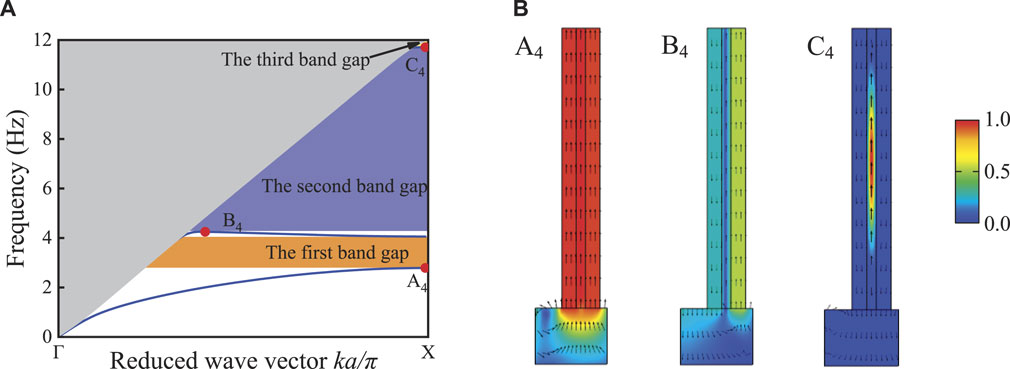
FIGURE 8. Band structure and displacement vector field of special points at tf = 0.125a: (A) band structure; (B) displacement vector field of special points.
Figure 9 shows the effect of height h and center radius r on the complete bandgap characteristic, where the height h and center radius r are generally considered to vary in the range of 1a-10a and 10a-100a, respectively. Figure 9A shows the relationship between the initial frequency (f1) of the first band gap and the height h and the center radius r. As the height h increases, fl shifts to low frequencies, which is caused by the constant increase in the equivalent mass of the LRSM-2. In addition, it is worth noting that when the LRSM-2 center radius is greater than 75a, for the lower height steel ring (h < 1.5a), f1 does not shift to high frequencies with decreasing height h, but remains at 3.6 Hz nearby, this is due to the fact that the LRSM-2 gradually equalizes the increment of the equivalent mass and the equivalent stiffness of the system with the increase of the center radius r, therefore, f1 remains almost unchanged. In addition, with the increase of the height h, the NRBW showed a trend of rapid increase; the increase of the center radius r also caused the increase of the NRBW. It can be observed that the structure height h has a more significant effect on NRBW. When the parameter h/a = 10, the NRBW can reach 83.9% (as shown in Figure 9B). The above results will better guide the design of LRSMs to obtain the desired bandgap properties in different geophysical environments.
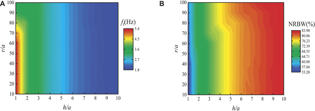
FIGURE 9. Relationship between bandgaps characteristics and parameter ratio h/a and r/a: (A) the lower frequency bounds of the first bandgaps (fl); (B) the relative band width of bandgap (NRBW).
In order to verify the shielding performance of LRSM-2, five periodic systems are designed in the transmission calculation as shown in Figure 10A. The base is soil, and the height of 20a is enough to ensure the separation of the body wave and the surface wave in the seismic wave, so that only the surface wave can reach the LRSM (Zeng et al., 2018). To prevent unwanted reflections caused by boundary wave scattering from the substrate region and bring the results closer to realistic conditions, a perfectly matched layer (PML) with a thickness of 3a was placed on the bottom and sides of the substrate. At line A, a line source is set up to simulate an incident wave as a generator of surface waves, where the line source vibrates at a monochromatic frequency with sagittal polarization characteristics that excite seismic waves on a uniform surface. The transmission quantities of seismic surface waves without LRSM and with LRSM in the range of 0.1–12 Hz are shown in Figure 10B, and complete attenuation areas are found in the ranges of 2.72–4.21 Hz and 4.38–11.96 Hz, which is consistent with Figure 3 The band gaps in (a) are consistent, and it can be found that within the band gap range, the amount of transmission with LRSM is significantly lower than that without LRSM.
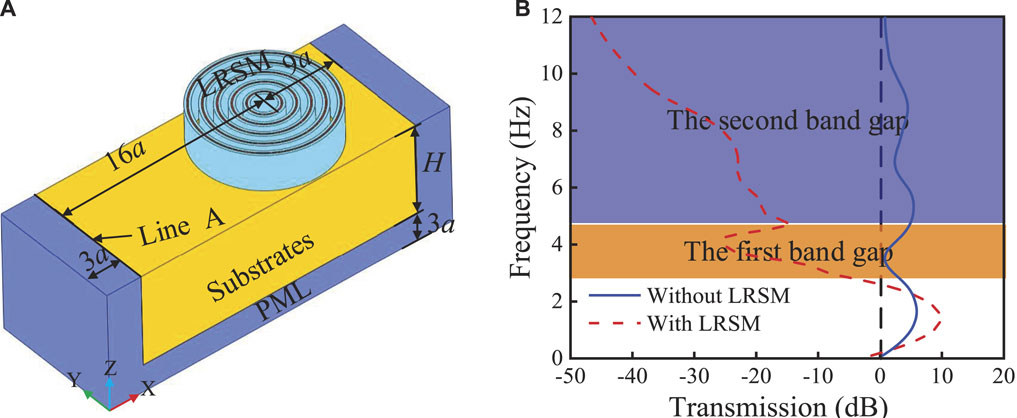
FIGURE 10. (A) Finite period system; (B) transmission curve.
Figures 11A,B show the propagation states of surface waves along the X direction in the soil without LRSM and with LRSM at 8 Hz, respectively. It can be seen from the figure that when there is no LRSM, the incident surface wave covers the soil matrix with almost no energy loss; while for the homogeneous soil with LRSM, the incident surface wave is effectively shielded. The X and Y components of the vibration displacement at the boundary line B are shown in Figures 11C,D, respectively. It can be observed from Figure 11C that the overall vibration displacement amplitude presents a maple leaf-shaped distribution, and the X component of the vibration displacement at the edge line B has a large difference in the circumferential distribution. The maximum vibration displacement value is 12.5 mm, located at 0°. The vibration displacement value is only 0.9 mm at the 135° position, so the LRSM dissipates energy differently around the circumference in resisting seismic waves. In Figure 11D, the vibration displacement of the Y component presents a butterfly-shaped symmetrical distribution as a whole in polar coordinates, and the displacement values are the largest at the positions of 45° and 315°. In actual construction, the position with large displacement can be reinforced, which can effectively improve its ability to resist seismic waves.
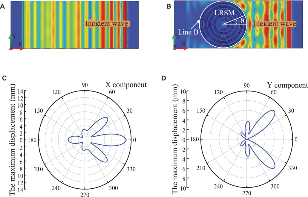
FIGURE 11. Schematic diagram of surface wave propagation in XY plane: (A) Without LRSM; (B) with LRSM-2; (C) vibration displacement value of X component at line B; (D) vibration displacement value of Y component at line (B)
Figures 12A,B show the XZ plane propagation states of surface waves in soils without and with LRSM, respectively. In Figure 12A, when the surface wave propagates in a half-space homogeneous medium, the energy is hardly attenuated, and it can carry energy for a long distance; in Figure 12B, the LRSM-2 band gap Surface waves are converted into body waves, and their vibrational energy is effectively dissipated, which is consistent with the “rainbow trap” effect (Colombi et al., 2016). The X and Z components of the vibrational displacement at line C are shown in Figures 11C,D, respectively. As shown in Figure 12C, the minimum value of the vibration displacement of line C on the X component appears at the inflection point of 2.9a, and its value is only 0.01 mm, the maximum displacement at the bottom is 12.5 mm, and the maximum displacement at the top is 11.7 mm, This shows that the line C presents a concave shape, and if its bottom is reinforced, such as burying the LRSM in the soil, its stability will be improved. In Figure 12D, due to the stable characteristics of the radial structure (Budiansky and Hutchinson, 1966), the vibration displacement of the Z component of line C is almost kept at around 2.7 mm, which is much smaller than that of the seismic metamaterial arranged based on Cartesian coordinates (Zeng et al., 2020), which is only 19.2% of its value, which indicates that the LRSM has better stability than the seismic metamaterial based on Cartesian coordinate arrangement (Miniaci et al., 2016).
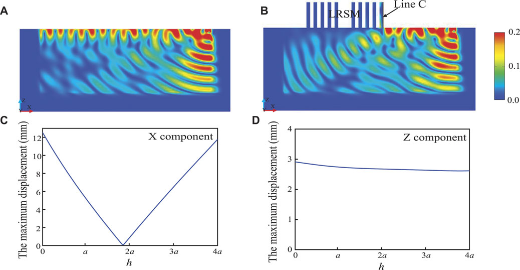
FIGURE 12. Schematic diagram of surface wave propagation in XZ plane: (A) Without LRSM; (B) with LRSM-2; (C) vibration displacement value of X component at line C; (D) vibration displacement value of Z component at line (C)
To investigate the effect of the LRSM system on the surface wave amplitude variation, a transient harmonic analysis was performed on a finite LRSM system with five periods. In this paper, the classical EI seismic wave signal (1940, El Centro Site, Vertical, Peak = 0.2468 g, Duration = 53.78 sec) and Taft seismic wave signal (Kishida et al., 2021) (1952, Taft Lincoln School, Peak = −0.1793 g, Duration = 54.40 s) are used respectively, as shown in Figures 13A,C, the acceleration spectrum of the seismic wave signal intercepts its first 30 s data, this range already contains the most intense part and main energy of the seismic record. Among them, the main frequency range of the seismic wave are concentrated in the frequency range of 0.1–10 Hz, as shown in Figures 13B,D. At line A, the Taft seismic wave excitation signal is input, and a transient explicit response with a duration of 35 s is performed to ensure that the seismic wave excitation signal emitted by line A can reach and pass through the LRSM. Apply low-reflection boundary conditions on the sides and bottom of the soil to simulate half-space and reduce reflections caused by the bottom and surrounding boundaries of the model.
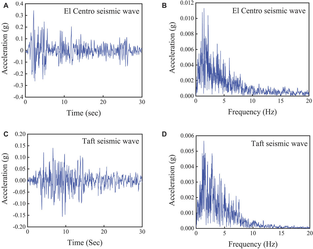
FIGURE 13. Seismic excitation signal: (A) time evolution of El Centro seismic signal; (B) frequency content of El Centro seismic wave signal; (C) time evolution of Taft seismic wave signal; (D) frequency content of Taft seismic wave signal.
Under the seismic wave excitation signal, the acceleration amplitude of the response signal at the axisymmetric center point with or without LRSM was recorded respectively (as shown in Figure 14A), in order to analyze the amplitude change of the surface wave in the region with or without LRSM. It can be observed from Figure 14 that due to the existence of LRSM, the vibration of the surface wave is effectively suppressed, and its maximum amplitude can be attenuated by more than 85% (wherein, the blue solid line represents the seismic wave amplitude signal without LRSM, and the red dotted line represents the seismic wave amplitude signal with LRSM. seismic wave amplitude signal). Subsequently, the acquired signal is Fourier transformed and the frequency content is compared to evaluate the damping performance of the LRSM, as shown in Figure 14B. The results show that the LRSM effectively attenuates seismic waves in the 0.1–20 Hz range, providing a virtually undisturbed region.
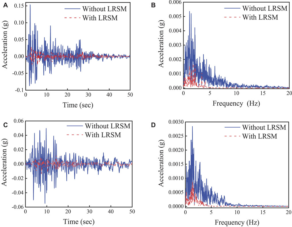
FIGURE 14. Excitation signal response: (A) excitation signal response of El Centro seismic wave; (B) fourier spectrum of El Centro seismic excitation signal response; (C) excitation signal response of Taft seismic wave; (D) fourier spectrum of Taft seismic excitation signal response.
The LRSM-2 designed in this paper is a circular ring with a larger diameter, but it is still inconvenient to arrange in engineering. Therefore, this section studies the effect of the internal circular continuity of the LRSM on the attenuation of surface waves. In the LRSM structure shown in Figure 11B, a thin PML layer is added every 60° (angle θ = 1°), and by changing the scale factor s of the PML, the energy propagation in the LRSM is controlled, which can be equivalent to Change the LRSM inner circumference continuity. As shown in Figure 15, when the internal circumferential continuity of the structure is changed, the local resonance effect of the LRSM is strengthened, and with the continuous increase of the scale factor s, the ability of the LRSM to attenuate surface waves is gradually enhanced. This is because the single period of LRSM is transformed from a single local oscillator resonance to a coupling resonance of multiple local oscillators. This means that in the construction of LRSM, the implementation scheme of block splicing can be adopted, which reduces the engineering difficulty and cost, and has better shielding characteristics.
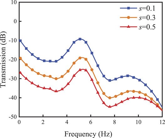
FIGURE 15. Transmission spectrum of LRSM under the influence of different scale factor s.
In this paper, a novel layered radial seismic metamaterial is proposed to block the effects of seismic surface waves on protected building areas. Using the finite element method, the dispersion curves of LRSMs with different layers in half space as seismic barriers are studied. Through the calculation of the displacement vector field, the ultra-low frequency broadband mechanism of the LRSM is discussed, and the influence of the geometric parameters and the circumferential continuity of the LRSM on the bandgap characteristics is discussed. Finally, dispersion analysis and full-scale 3D transient wave propagation simulations are performed in a finite-period system to evaluate its damping performance.
The results show that the LRSM has ultra-low frequency broadband characteristics and can effectively attenuate seismic surface waves in the range of 0.1–20 Hz, and the maximum amplitude attenuation exceeds 85%. For LRSM, the increase of the number of layers will generate new band gaps, but the initial frequency and total bandwidth do not show monotonic changes like traditional seismic metamaterials, but show optimal band gap characteristics when the structure is LRSM-2 (The band gap relative bandwidth NRBW can exceed 80%). Compared with traditional seismic metamaterials, LRSMs have only a single axial resonance, which is caused by the circumferential stability of LRSMs. Further, by observing the dispersion curve of the LRSM, when the number of layers of the steel ring increases, new flat bands will appear. The stiffness will affect the local resonance strength. By analyzing the vibration displacement of LRSM in the circumferential and axial directions, it is shown that the energy dissipation of RSM is mainly concentrated in the circumferential direction, and the distribution is different; the vibration displacement value along the axial direction is only 2.7 mm, which is much lower than that of traditional seismic metamaterials. It is shown that LRSM has better stability in resisting seismic waves. The position and width of the band gap in the LRSM are very sensitive to the structure height, and the increase of the LRSM height can move the first band gap to the low frequency, and the total bandwidth increases, mainly due to the increase of the system equivalent mass Me with the increase of the height h. With the decrease of the circumferential continuity of the LRSM, the LRSM gradually transforms from the overall ring oscillator resonance to the coupling of multiple sector oscillator resonances, and the ability to attenuate surface waves is continuously enhanced. This paper demonstrates the feasibility of radial periodic structures as seismic wave shielding. The proposed radial metamaterials provide new design guidelines for solving engineering problems such as vibration and noise in half space.
The datasets presented in this study can be found in online repositories. The names of the repository/repositories and accession number(s) can be found in the article/Supplementary Material.
The contribution of HL is analysising the model. The contribution of LL, QJ, PL, and XZ is data processing.
The Natural Science Foundation of China Shaanxi Province under Grant No. 15JK1405, National Natural Science Foundation of China under Grant No. 51405368 and Natural Science Foundation of China Shaanxi Province under Grant No. 2017JM5024 have supported this research.
The authors declare that the research was conducted in the absence of any commercial or financial relationships that could be construed as a potential conflict of interest.
All claims expressed in this article are solely those of the authors and do not necessarily represent those of their affiliated organizations, or those of the publisher, the editors and the reviewers. Any product that may be evaluated in this article, or claim that may be made by its manufacturer, is not guaranteed or endorsed by the publisher.
Achaoui, Y., Antonakakis, T., Brûlé, S., Craster, R. V., Enoch, S., and Guenneau, S. (2017). Clamped Seismic Metamaterials: Ultra-low Frequency Stop Bands. New J. Phys. 19 (6), 063022. doi:10.1088/1367-2630/aa6e21
Achaoui, Y., Ungureanu, B., Enoch, S., Brûlé, S., and Guenneau, S. (2016). Seismic Waves Damping with Arrays of Inertial Resonators. Extreme Mech. Lett. 8, 30–37. doi:10.1016/j.eml.2016.02.004
An, S., Shu, H., Liang, S., Shi, X., and Zhao, L. (2018). Band gap Characteristics of Radial Wave in a Two-Dimensional Cylindrical Shell with Radial and Circumferential Periodicities. AIP Adv. 8 (3), 035110. doi:10.1063/1.5023734
Brûlé, S., Javelaud, E. H., Enoch, S., and Guenneau, S. (2014). Experiments on Seismic Metamaterials: Molding Surface Waves. Phys. Rev. Lett. 112 (13), 133901. doi:10.1103/PhysRevLett.112.133901
Budiansky, B., and Hutchinson, J. W. (1966). A Survey of Some Buckling Problems. AIAA J. 4 (9), 1505–1510. doi:10.2514/3.3727
Carbonell, J., Torrent, D., Díaz-Rubio, A., and Sánchez-Dehesa, J. (2011). Multidisciplinary Approach to Cylindrical Anisotropic Metamaterials. New J. Phys. 13 (10), 103034. doi:10.1088/1367-2630/13/10/103034
Chen, Y., and Wang, L. (2014). Isolation of Surface Wave-Induced Vibration Using Periodically Modulated Piles. Int. J. Appl. Mech. 06 (04), 1450042. doi:10.1142/s1758825114500422
Colombi, A., Roux, P., Guenneau, S., Gueguen, P., and Craster, R. V. (2016). Forests as a Natural Seismic Metamaterial: Rayleigh Wave Bandgaps Induced by Local Resonances. Sci. Rep. 6 (1), 19238. doi:10.1038/srep19238
Dobrin, M. B., and Savit, C. H. (1960). Introduction to Geophysical Prospecting. New York: McGraw-Hill.
Du, Q., Zeng, Y., Huang, G., and Yang, H. (2017). Elastic Metamaterial-Based Seismic Shield for Both Lamb and Surface Waves. AIP Adv. 7 (7), 075015. doi:10.1063/1.4996716
Du, Q., Zeng, Y., Xu, Y., Yang, H., and Zeng, Z. (2018). H-fractal Seismic Metamaterial with Broadband Low-Frequency Bandgaps. J. Phys. D: Appl. Phys. 51 (10), 105104. doi:10.1088/1361-6463/aaaac0
Elford, D. P., Chalmers, L., Kusmartsev, F. V., and Swallowe, G. M. (2011). Matryoshka Locally Resonant Sonic crystal. The J. Acoust. Soc. America 130 (5), 2746–2755. doi:10.1121/1.3643818
Gao, N., Hou, H., Wu, J. H., and Cheng, B. (2016a). Low Frequency Band Gaps below 10 Hz in Radial Flexible Elastic Metamaterial Plate. J. Phys. D: Appl. Phys. 49 (43), 435501. doi:10.1088/0022-3727/49/43/435501
Gao, N., Hou, H., and Xin, H. (2017). A Single and Double Slotting Radial Acoustic Metamaterial Plate. Mod. Phys. Lett. B 31 (12), 1750128. doi:10.1142/s0217984917501287
Gao, N., Wu, J. H., Yu, L., and Xin, H. (2016b). Design of Radial Phononic crystal Using Annular Soft Material with Low-Frequency Resonant Elastic Structures. Phys. Lett. A 380 (41), 3326–3332. doi:10.1016/j.physleta.2016.08.010
Jiang, T., and He, Q. (2017). Dual-directionally Tunable Metamaterial for Low-Frequency Vibration Isolation. Appl. Phys. Lett. 110 (2), 021907. doi:10.1063/1.4974034
Kim, S.-H., and Das, M. P. (2012). Seismic Waveguide of Metamaterials. Mod. Phys. Lett. B 26 (17), 1250105. doi:10.1142/s0217984912501059
Kishida, T., Contreras, V., Bozorgnia, Y., Abrahamson, N. A., Ahdi, S. K., Ancheta, T. D., et al. (2021). NGA-sub Ground Motion Database. Abu Dhabi, United Arab Emirates: UCLA. Retrieved from https://escholarship.org/uc/item/3bn528xc.
Krödel, S., Thomé, N., and Daraio, C. (2015). Wide Band-gap Seismic Metastructures. Extreme Mech. Lett. 4, 111–117. doi:10.1016/j.eml.2015.05.004
Li, J., and Chan, C. T. (2004). Double-negative Acoustic Metamaterial. Phys. Rev. E Stat. Nonlin Soft Matter Phys. 70 (5), 055602. doi:10.1103/PhysRevE.70.055602
Li, Y., Chen, T., Wang, X., Yu, K., and Chen, W. (2014). Propagation of Lamb Waves in One-Dimensional Radial Phononic crystal Plates with Periodic Corrugations. J. Appl. Phys. 115 (5), 054907. doi:10.1063/1.4864425
Lim, C., and Reddy, J. (2019). Built-up Structural Steel Sections as Seismic Metamaterials for Surface Wave Attenuation with Low Frequency Wide Bandgap in Layered Soil Medium. Eng. Structures 188, 440–451. doi:10.1016/j.engstruct.2019.03.046
Liu, Z., Qin, K.-Q., and Yu, G.-L. (2020). Partially Embedded Gradient Metabarrier: Broadband Shielding from Seismic Rayleigh Waves at Ultralow Frequencies. J. Eng. Mech. 146 (5), 04020032. doi:10.1061/(asce)em.1943-7889.0001752
Ma, T., Chen, T., Wang, X., Li, Y., and Wang, P. (2014). Band Structures of Bilayer Radial Phononic crystal Plate with crystal Gliding. J. Appl. Phys. 116 (10), 104505. doi:10.1063/1.4895138
Miniaci, M., Krushynska, A., Bosia, F., and Pugno, N. M. (2016). Large Scale Mechanical Metamaterials as Seismic Shields. New J. Phys. 18 (8), 083041. doi:10.1088/1367-2630/18/8/083041
Neto, A. G., e Silva, J. C., de Carvalho, J. N., do Nascimento Cruz, J., and Ferreira, H. P. A. (2015). “Analysis of the Resonant Behavior of FSS Using Matryoshka Geometry,” in 2015 SBMO/IEEE MTT-S International Microwave and Optoelectronics Conference (IMOC) (João Pessoa, Brazil: IEEE), 1–5.
Norris, R. C., Hamel, J. S., and Nadeau, P. (2008). Phononic Band gap Crystals with Periodic Fractal Inclusions: Theoretical Study Using Numerical Analysis. J. Appl. Phys. 103 (10), 104908. doi:10.1063/1.2931955
Palermo, A., Krödel, S., Marzani, A., and Daraio, C. (2016). Engineered Metabarrier as Shield from Seismic Surface Waves. Sci. Rep. 6 (1), 39356. doi:10.1038/srep39356
Pennec, Y., Vasseur, J. O., Djafari-Rouhani, B., Dobrzyński, L., and Deymier, P. A. (2010). Two-dimensional Phononic Crystals: Examples and Applications. Surf. Sci. Rep. 65 (8), 229–291. doi:10.1016/j.surfrep.2010.08.002
Reitherman, R. K. (2012). Earthquakes and Engineers: An International History. Reston, VA: American Society of Civil Engineers.
Shi, X., Shu, H., Zhu, J., Wang, X., Dong, L., Zhao, L., et al. (2016). Research on Wave Bandgaps in a Circular Plate of Radial Phononic crystal. Int. J. Mod. Phys. B 30 (23), 1650162. doi:10.1142/s0217979216501629
Shu, H.-S., Wang, X.-G., Liu, R., Li, X.-G., Shi, X.-N., Liang, S.-J., et al. (2015). Bandgap Analysis of Cylindrical Shells of Generalized Phononic Crystals by Transfer Matrix Method. Int. J. Mod. Phys. B 29 (24), 1550176. doi:10.1142/s0217979215501763
Telford, W. M., Telford, W., Geldart, L., Sheriff, R. E., and Sheriff, R. E. (1990). Applied Geophysics. Cambridge, United Kingdom: Cambridge University Press.
Torrent, D., and Sánchez-Dehesa, J. (2009). Radial Wave Crystals: Radially Periodic Structures from Anisotropic Metamaterials for Engineering Acoustic or Electromagnetic Waves. Phys. Rev. Lett. 103 (6), 064301. doi:10.1103/PhysRevLett.103.064301
Torrent, D., and Sánchez-Dehesa, J. (2010a). Acoustic Resonances in Two-Dimensional Radial Sonic crystal Shells. New J. Phys. 12 (7), 073034. doi:10.1088/1367-2630/12/7/073034
Torrent, D., and Sánchez-Dehesa, J. (2010b). Anisotropic Mass Density by Radially Periodic Fluid Structures. Phys. Rev. Lett. 105 (17), 174301. doi:10.1103/physrevlett.105.174301
Ungureanu, B., Achaoui, Y., Enoch, S., Brûlé, S., and Guenneau, S. (2015). Auxetic-like Metamaterials as Novel Earthquake Protections. arXiv 2, 17–30. preprint arXiv:1510.08785. doi:10.1051/epjam/2016001
Wang, L., Xia, D., Fu, Q., Ding, X., and Wang, Y. (2021). A Switchable Ultra-wideband Metamaterial Absorber with Polarization-Insensitivity and Wide-Incident Angle at THz Band. Front. Mater. 8, 296. doi:10.3389/fmats.2021.729495
Wang, Y.-F., Wang, Y.-S., and Laude, V. (2015). Wave Propagation in Two-Dimensional Viscoelastic Metamaterials. Phys. Rev. B 92 (10), 104110. doi:10.1103/physrevb.92.104110
Wilson, G., Wilson, T. M., Deligne, N. I., and Cole, J. W. (2014). Volcanic hazard Impacts to Critical Infrastructure: A Review. J. Volcanology Geothermal Res. 286, 148–182. doi:10.1016/j.jvolgeores.2014.08.030
Xu, Z., Wu, F., and Guo, Z. (2012). Low Frequency Phononic Band Structures in Two-Dimensional Arc-Shaped Phononic Crystals. Phys. Lett. A 376 (33), 2256–2263. doi:10.1016/j.physleta.2012.05.037
Zeng, Y., Xu, Y., Deng, K., Peng, P., Yang, H., Muzamil, M., et al. (2019). A Broadband Seismic Metamaterial Plate with Simple Structure and Easy Realization. J. Appl. Phys. 125 (22), 224901. doi:10.1063/1.5080693
Zeng, Y., Xu, Y., Deng, K., Zeng, Z., Yang, H., Muzamil, M., et al. (2018). Low-frequency Broadband Seismic Metamaterial Using I-Shaped Pillars in a Half-Space. J. Appl. Phys. 123 (21), 214901. doi:10.1063/1.5021299
Keywords: elastic metamaterial, local resonance, band gap, finite element method, axisymmetric model
Citation: Liu H, Li L, Jia Q, Jiang S, Li P and Zhang X (2022) Radial Seismic Metamaterials Based on Layering Theory: Broadband Shielding of Ultra-Low Frequency Seismic Surface Waves. Front. Mater. 9:908058. doi: 10.3389/fmats.2022.908058
Received: 30 March 2022; Accepted: 12 April 2022;
Published: 10 May 2022.
Edited by:
Fuyin Ma, Xi’an Jiaotong University, ChinaReviewed by:
Xianchen Xu, University of Missouri, United StatesCopyright © 2022 Liu, Li, Jia, Jiang, Li and Zhang. This is an open-access article distributed under the terms of the Creative Commons Attribution License (CC BY). The use, distribution or reproduction in other forums is permitted, provided the original author(s) and the copyright owner(s) are credited and that the original publication in this journal is cited, in accordance with accepted academic practice. No use, distribution or reproduction is permitted which does not comply with these terms.
*Correspondence: Lixia Li, amllbGlfMThAMTYzLmNvbQ==
Disclaimer: All claims expressed in this article are solely those of the authors and do not necessarily represent those of their affiliated organizations, or those of the publisher, the editors and the reviewers. Any product that may be evaluated in this article or claim that may be made by its manufacturer is not guaranteed or endorsed by the publisher.
Research integrity at Frontiers
Learn more about the work of our research integrity team to safeguard the quality of each article we publish.