 Yuming Yang
 Huilong Duan1
94% of researchers rate our articles as excellent or good
Learn more about the work of our research integrity team to safeguard the quality of each article we publish.
Find out more
ORIGINAL RESEARCH article
Front. Mater., 11 April 2022
Sec. Metamaterials
Volume 9 - 2022 | https://doi.org/10.3389/fmats.2022.894074
This article is part of the Research TopicAcoustic and Mechanical Metamaterials for Various ApplicationsView all 13 articles
This study is motivated to quantitatively analyze the differences among various multiple scattering models to determine the role played by the scatterer type in ultrasonic wave propagation. By calculating the transmission and reflection coefficients of the composites, the results of multiple scattering theoretical models of different scatterer types have been evaluated. The problem of acoustic properties in a fluid matrix containing different types of micron-scale scatterers operating in the ultrasound frequency range is considered. Theoretical calculations are conducted for composites with different mechanical properties. Meanwhile, the theoretical results have been compared with numerical finite element method simulations, which can be regarded as a benchmark to verify the validity of different theoretical models. The results show that the composites can achieve negative acoustic properties by selecting appropriate resonant scatterers, paving the way for searching ultrasonic metamaterials with desired negative acoustic properties. We further explored the application of microstructure ultrasonic metamaterials by enhancing the ultrasound transmitted energy through the high-impendence skull layer, having the potential for non-invasive ultrasound brain imaging and therapy.
Acoustic metamaterials (AMMs) are special composite structures with exotic properties that natural materials do not possess (Lee et al., 2017; Liu et al., 2020). In recent years, the studies of AMMs have paved the way for diverse applications such as acoustic cloaking (Zigoneanu et al., 2014), sound absorption (Yang and Sheng, 2017; Xiao et al., 2022), acoustic imaging (Deng et al., 2009; Zhu et al., 2011; Dong et al., 2018), impedance matching (D’Aguanno et al., 2012), focusing (Zhang et al., 2009; Page, 2016), and canceling out aberrating layers (Shen et al., 2014; Craig et al., 2019). However, the current research study on AMMs mostly focuses on audible sound frequency. The successful application of ultrasonic metamaterials still faces considerable challenges due to the long-wavelength limitation, therefore insisting the need to design, simulate, and fabricate micrometer-scale size AMM resonant scatterers.
Current studies of ultrasonic metamaterials mainly utilize strong Mie-type resonances (Brunet et al., 2013) to exhibit negative acoustic properties, using scatterers randomly suspended in a fluid matrix phase. For over a century, numerous models of multiple scattering of randomly suspended scatterers in composites for inhomogeneous media have been studied. Foldy first proposed the multiple scattering theory (MST) to calculate the effective wavenumber in composites with isotropic scatterers in a fluid matrix (Foldy, 1945). The MST model was further extended to anisotropic scatterers by Waterman and Truell (Waterman and Truell, 1961), Lloyd and Berry (Lloyd and Berry, 1967), Linton and Martin (Linton and Martin, 2005), and Luppé and Conoir (Luppé and Conoir, 2011). This prompted us to investigate whether these models are still efficient for calculating ultrasound wave propagation in composites with randomly suspended microstructure scatterers.
In this study, the acoustic properties of two-dimensional micron-scale scatterers randomly immersed in a fluid matrix have been considered. The role played by the type of scatterers in the propagation of ultrasound waves is investigated. The transmission and reflection coefficients have been analyzed via the effective wavenumber and the effective impedance of the composites. Meanwhile, the acoustic properties of the microstructure composites have been further addressed by the finite element method (FEM) model. Therefore, the numerical simulation benchmark allows us to specify the validity domains for each of these analytical methods under study. Another aspect of this work is to figure out the potential application of the microstructure ultrasonic metamaterials. With the capacity of enhancing the transmitted energy through the skull, this type of ultrasonic metamaterials has the potential for non-invasive ultrasound brain imaging and therapy.
For a clear presentation of the computational approach for the calculation and simulation of transmission and reflection coefficients, a random distribution of two-dimensional scatterers immersed in a fluid matrix was considered in this study. We suppose N scatterers are suspended in the slab region of thickness d. The scatterers have identical cylindrical geometry and are uniformly and randomly distributed. The screen of scatterers is insonified by a normal incident plane wave from the left, as shown in Figure 1A; the multiple scattering of ultrasound can be considered as energy transport; some energy from the forward wave is dissipated within the scatterers, while the other portion is transferred to the back wave. The MST theoretical model (Figures 1B,C) is used to obtain the transmission and reflection coefficients of random distributions of scatterers and then compared with the benchmark value from the FEM numerical simulation (Figure 1D).
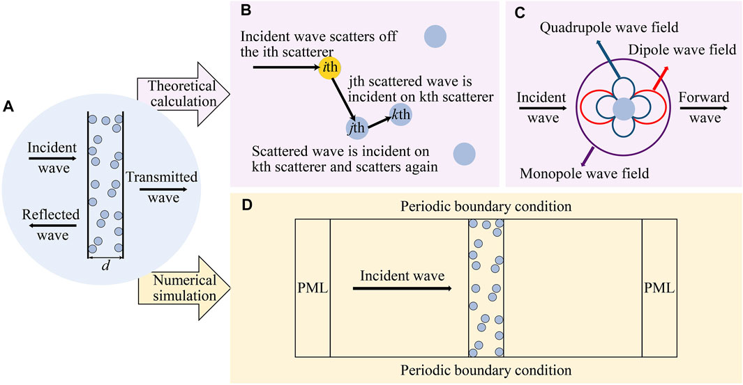
FIGURE 1. (A) Random distribution of scatterers immersed in a fluid matrix. (B) Schematic diagram demonstrating multiple scattering of the incident wave by several scatterers. (C) Monopole, dipole, and quadrupole resonances due to the mechanical contrast between a single scatterer and the fluid matrix. (D) Schematic diagram showing the geometry and boundary conditions used in the numerical simulation FEM model.
Under the influence of an incident wave, multiple scattering occurs inside the scatterers, as shown in Figure 1B. Depending on the MST, the scattered wave generated by the ith scatterer will affect its adjacent scatterers. For an adjacent jth scatterer, the scattered wave excited by the ith scatterer can be regarded as an incident wave, which interacts with the jth scatterer to excite a scattered wave; it can also be regarded as an incident wave of the kth scatterer and so on (Waterman and Truell, 1961). The MST mainly focuses on calculating the effective dynamic properties of random distributions of scatterers, and its basic problem is the scattering of a single scatterer, as shown in Figure 1C. When the scatterer radius is much smaller than the wavelength, multiple resonance modes arise due to the mechanical contrast between a single scatterer and the fluid matrix, which creates movement of the scatters relative to the fluid matrix (Kafesaki et al., 2000), a monopole resonance due to the velocity contrast, a dipole resonance due to the density contrast, and a quadrupole resonance due to the shear modulus contrast. In particular, when the velocity within the scatterers is much slower than that of the fluid matrix, multiple Mie-type resonances can be exhibited. The effective properties of random composites are deeply altered close to the particle frequency resonances, opening up possibilities to achieve ultrasonic metamaterials with negative acoustic properties. In the long-wavelength limit region, the corresponding possible scatterer size is reduced to the micrometer size in water for ultrasound frequency (Povey, 2013). The fact that whether the MST can analyze the acoustic properties of ultrasonic metamaterials with low-velocity micron-scale scatterers randomly immersed in a fluid matrix is also discussed in this article.
To verify the applicability of the MST for composites operating in the ultrasound frequency region, numerical FEM simulation values of the transmission and reflection coefficients are used as the benchmark, as shown in Figure 1D. The numerical simulation results are compared with the theoretical model predictions to analyze different analytical MST methods.
Multiple scattering by scatterers suspended in composites is a fundamental topic with the extensive literature. The estimation of the effective properties of composites is very significant for the design and preparation of composites. So far, many related approaches and predictive models have been proposed. As early as 1945, Foldy et al. proposed the MST for waves that are isotropically scattered by randomly distributed scatterers. Since the specific configuration of the amorphously distributed scatterers is not important, the configuration of the obstacles can be considered as the average of one state in an ensemble. Foldy considered the first order of the scattering coefficient for a single scattering and obtained Eq. 1 to calculate the frequency-dependent complex wavenumber
Waterman and Truell further improved Foldy’s method by introducing quadratic terms for the number of scatterers, laying a foundation for other multiple scattering theories. Their most important result is that the wave propagation in the scattering medium can be described by the far-field amplitude
where
where
Eq. 5 is different from Eq. 2 by the Waterman and Truell framework, both in the signs of the forward and backscattered terms and in the additional modified term of
Based on the effective wavenumber in the Waterman and Truell framework, Angel and Aristégui further described the effective medium by the reflection coefficient and the transmission coefficient (Angel and Aristégui, 2005; Aristégui and Angel, 2007).
where
where
where
Recently, Luppé and Conoir further obtained the EMD, EBM, and effective impedance as
with
The effective mass density and effective impedance in the Angel and Aristégui framework and Luppé and Conoir framework are equal when only the first order of
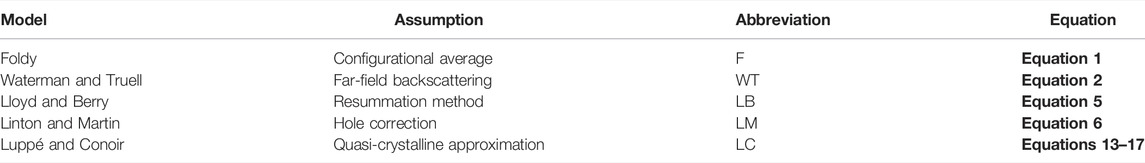
TABLE 1. Assumption theory, abbreviations, and calculation equations of five different MST models.
Multiple scattering signals are composed of coherent parts and incoherent parts. Since enough scatterer position configurations are averaged, the incoherent part vanishes in MST theoretical calculations. In practice, it is not easy to obtain coherent wave characteristics by using only one sample of random composite because it requires a large number of local measurements along the composite to restore the averaging procedure. Therefore, numerical simulations are a good choice.
The numerical simulations were finished by COMSOL Multiphysics software in the pressure acoustic frequency domain. The designed numerical simulation geometric model is shown in Figure 1D. A slab of screen
It is necessary to establish a precise framework to limit the study field and focus on the role played by microstructures. The purpose of this part is to study the influence of the scatterer type on the ultrasound wave propagation in composites. In the previous section, we summarized the aforementioned five theoretical models of characterizing the scattering medium; now, we compared the results obtained by five different MST theoretical models under the benchmark of the FEM simulations.
To go further into the analysis of the impact of the microstructure scatterers type in general, we studied two different types of scatterers. Case I: steel scatterers are immersed in the water matrix. Case II: rubber scatterers are suspended in the water matrix. In both cases, the radius of the scatterers is set at 60 μm with ϕ = 20.94% to satisfy the long-wavelength limit in ultrasound frequency. Parameters of the used materials are listed in Table 2.
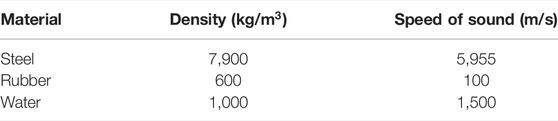
TABLE 2. Acoustic properties of the materials.
We considered the propagation of coherent waves through steel scatterers randomly immersed in water. Figure 2A and Figure 2B present the modulus of complex transmission and reflection coefficients corresponding to steel scatterers in water, according to MST frameworks (Table 1) and FEM simulations. Both in Figure 2A and Figure 2B, the transmission coefficients obtained by four MST frameworks (WT, LB, LM, and LC) agree with each other, except the Foldy framework (F) as expected. It indicates that Foldy only considered the forward far-field scattering amplitude without considering the important role of the backscattered amplitude. Therefore the scattering amplitude of
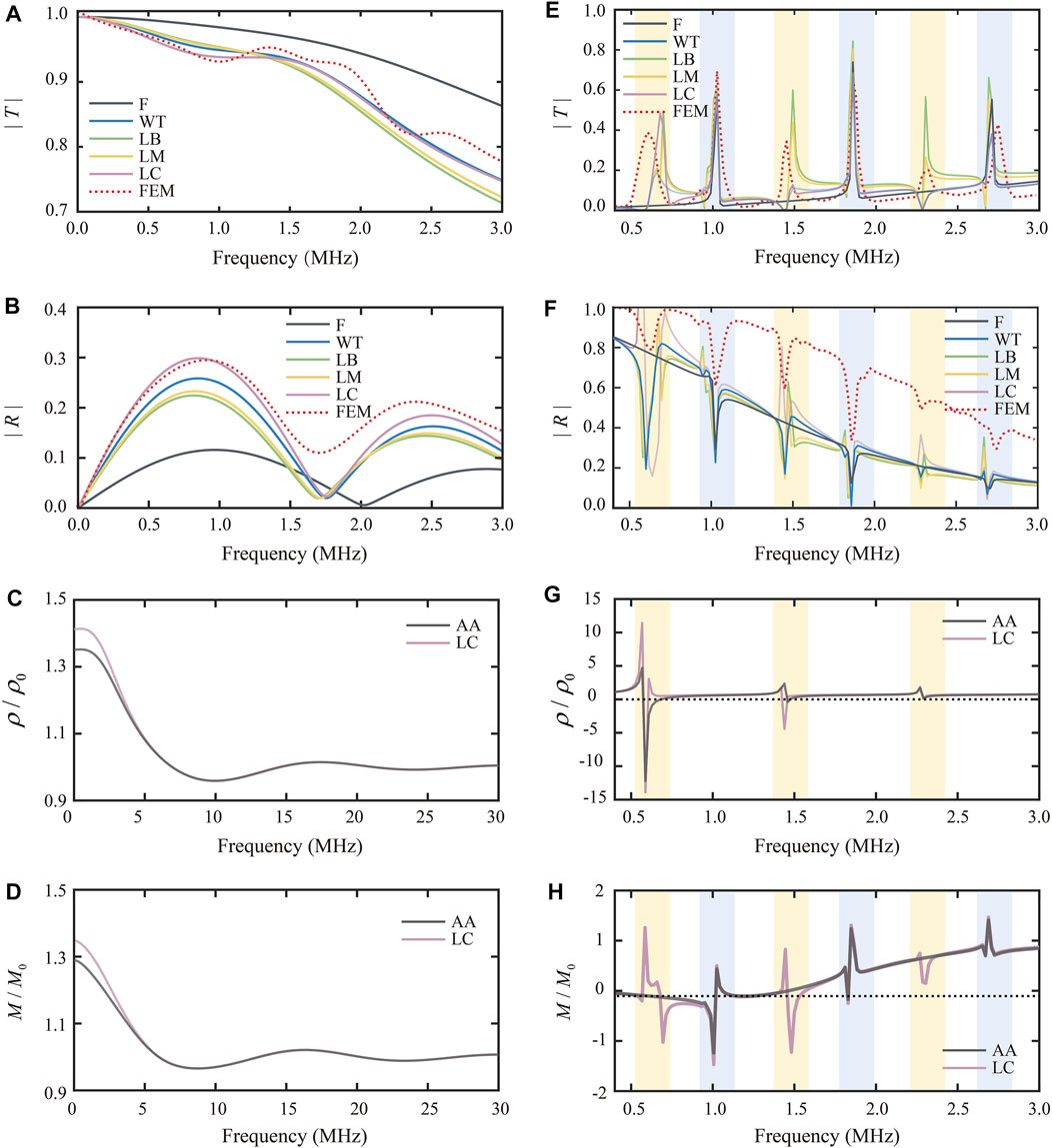
FIGURE 2. Comparison of transmission and reflection coefficients moduli for different types of scatterers suspended in water by MST models and FEM simulations and calculation results of the real parts of the EMD and EBM corresponding to different type scatterers. (A) Modulus of the transmission coefficient versus frequency corresponding to steel scatterers in water. (B) Modulus of the reflection coefficient versus frequency corresponding to steel scatterers in water. (C) Real part of the EMD versus frequency corresponding to steel scatterers in water. (D) Real part of the EBM versus frequency corresponding to steel scatterers in water. (E) Modulus of the transmission coefficient versus frequency corresponding to rubber scatterers in water. (F) Modulus of the reflection coefficient versus frequency corresponding to rubber scatterers in water. (G) Real part of the EMD versus frequency corresponding to rubber scatterers in water. (H) Real part of the EBM versus frequency corresponding to rubber scatterers in water.
It is worth noting that the approximation formulas for LB and LM frameworks are very similar, which is also evidenced by the fact that the LM framework curves are particularly close to the LB framework curves, as shown in Figure 2A and Figure 2B.
AMMs with negative EMD and/or EBM have been studied extensively, which can cause a lot of exotic acoustic properties. To enhance our analysis, we have investigated the EMD and EBM for the microstructure composites. Figure 2C and Figure 2D show the real parts of the EMD and EBM, according to two different MST frameworks, the Angel and Aristégui framework (Eq. 10 and Eq. 11) and LC framework (Eq. 13 and Eq. 14). As observed in Figure 2A and Figure 2B, the transmission and reflection coefficients of steel scatterers in water display no resonance peaks. Therefore, the real parts of the EMD and EBM are decreasing from the static limit to unit one with increasing frequency. At a high frequency, the real parts of the EMD and EBM approach unity, and the imaginary parts of the EMD and EBM tend to zero. These results demonstrate that the EMD and EBM tend to reach that of water at a high frequency; in other words, there is no contribution in the density and modulus from the steel scatterers.
For the second case, rubber scatterers in water, it is notable to see resonances at specific frequency regions. Figure 2E and Figure 2F show the moduli of transmission and reflection coefficients corresponding to rubber scatterers in water. For transmission coefficients (Figure 2E), the frequency regions of the resonances peaks in the MST models are consistent with those in FEM simulation, except the Foldy framework misses three main resonance peaks in 0.4–3 MHz. Once again, it indicates that Foldy only considered the forward far-field scattering amplitude. However, out of resonant frequency regions (around 1.02 and 1.87 MHz), MST models provide results significantly different from FEM simulations. It can be explained that the scatterers reach a steady state at the specific narrow resonant frequency, and a large amount of energy is stored at this frequency region. As less energy is transmitted in the fluid, this reduces the intensity of interactions between scatterers meanwhile. Once out of the steady state, MST models only calculate the coherent part but the incoherent part superposition decreases the amplitude of the transmitted wave. We also noticed that the oscillation of the WT framework at resonance frequency regions appeared visibly smoother than that of LB, LM, and LC frameworks, which can be regarded as the influence of the microstructure type. LB, LM, and LC frameworks have an additional term of
Figure 2G and Figure 2H show the real parts of the EMD and EBM corresponding to rubber scatterers in water. We noted that in six particular frequency regions, the moduli of transmission and reflection coefficients show obvious resonance peaks, which are around 0.57, 1.02, 1.44, 1.87, 2.28, and 2.75 MHz, respectively, within the ultrasound frequency range of 0.4–3 MHz. At six resonance peak frequencies, most of the incident energy is transmitted. As shown in Figure 3, rubber scatterers exhibit a variety of resonance modes at these specific frequencies, whereas at the non-resonant frequencies (Figure 3A), most of the energy is reflected by the composites. In the aforementioned narrow frequency regions, the EMD or EBM also show a negative value. There are negative resonant peaks in the EMD near 0.57 and 1.44 MHz (Figure 2G). For the Angel and Aristégui framework (AA framework), negative resonant peaks are formed in the EBM near 1.02 and 1.87 MHz. For the LC framework, negative resonant peaks in the EBM are observed near 0.57, 1.02, 1.44, and 1.87 MHz (Figure 2H). In the LC framework, the quadratic coefficient of the scatterer number is modified, which results in the difference compared with the AA framework. We can see that EBM results exhibit three more peaks compared to the AA framework (Figure 2H), but these are not shown in Figure 2D. Once again, it can be considered to be influenced by the type of the microstructure. When using ultra-slow Mie-type microstructure scatterers, the correction to
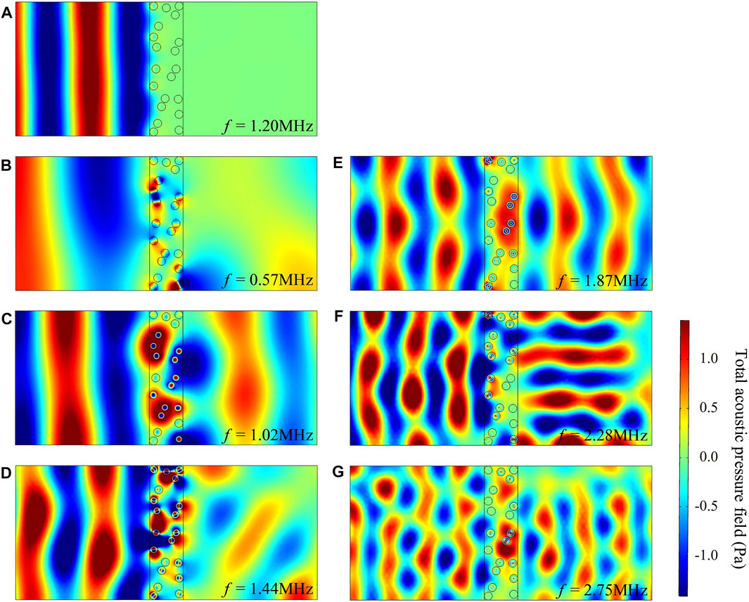
FIGURE 3. Total acoustic pressure field at seven different frequencies corresponding to rubber scatterers in water. (A) Total acoustic pressure field at non-resonant frequency 1.20 MHz. (B)–(G) Total acoustic pressure field at six different resonant frequencies: 0.57, 1.02, 1.44, 1.87, 2.28, and 2.75 MHz, respectively.
The aforementioned results illustrate that the MST theoretical calculation models are capable of analyzing ultrasonic metamaterials with negative effective properties. We chose soft rubber scatterers with low velocity and density suspended in water and a high fraction of scatterers to exhibit strong Mie-type resonances to recognize negative effect properties (Ba et al., 2017). In addition, the application of this ultrasonic metamaterial is further explored, depending on the research on complementary acoustic metamaterials (Shen et al., 2014); the imaging aberration skull layer is used to demonstrate whether the ultrasonic metamaterial in this study can enhance the ultrasound transmission through the skull. A numerical model was further achieved by using FEM simulations by COMSOL Multiphysics software. As shown in Figure 4, after the ultrasonic metamaterial layer is added in front of the skull layer
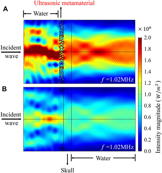
FIGURE 4. Ultrasound intensity distribution under two conditions. (A) Ultrasonic metamaterial is placed in front of the skull layer. (B) Only skull layer without the ultrasonic metamaterial.
In this study, the transmission and reflection coefficients calculating results of five MST theoretical frameworks (Foldy, Waterman & Truell, Lloyd & Berry, Linton & Martin, and Luppé & Conoir) are compared with the FEM simulations. Hard steel scatterers and soft Mie-type scatterers randomly suspended in water operating at the ultrasound frequency region are taken into consideration. In the calculation of soft scatterers with a low velocity immersed in water, the resonances became sharp due to the contrast between the scatterers and the matrix. MST models can still analyze this type of ultrasonic metamaterials with negative properties. The application of this ultrasonic metamaterial is also simulated, and this ultrasonic metamaterial can counteract the attenuation of ultrasound transmission by the high-impedance layer. The intensity of ultrasound through the skull layer is increased by 200% when the ultrasonic metamaterial layer is added, paving the way for further non-invasive ultrasound imaging and therapy through the skull.
The original contributions presented in the study are included in the article/Supplementary Material, further inquiries can be directed to the corresponding author.
YY, HD, and YZ initiated the project. YY wrote the manuscript, carried out the theoretical calculations, and numerical simulations. All the authors contributed to the editing of the manuscript.
This work was supported by the National Key R&D Program of China (2018YFC0114900). The Zhejiang Provincial Key R&D Program of China (2022C01002). The National Major Scientific Research Instrument Development Project (81827804).
The authors declare that the research was conducted in the absence of any commercial or financial relationships that could be construed as a potential conflict of interest.
All claims expressed in this article are solely those of the authors and do not necessarily represent those of their affiliated organizations, or those of the publisher, the editors, and the reviewers. Any product that may be evaluated in this article, or claim that may be made by its manufacturer, is not guaranteed or endorsed by the publisher.
Angel, Y. C., and Aristégui, C. (2005). Analysis of Sound Propagation in a Fluid through a Screen of Scatterers. The J. Acoust. Soc. America 118 (1), 72–82. doi:10.1121/1.1931088
Aristégui, C., and Angel, Y. C. (2007). Effective Mass Density and Stiffness Derived from P-Wave Multiple Scattering. Wave Motion 44 (3), 153–164. doi:10.1016/j.wavemoti.2006.08.005
Ba, A., Kovalenko, A., Aristégui, C., Mondain-Monval, O., and Brunet, T. (2017). Soft Porous Silicone Rubbers with Ultra-low Sound Speeds in Acoustic Metamaterials. Sci. Rep. 7 (1), 1–6. doi:10.1038/srep40106
Brunet, T., Leng, J., and Mondain-Monval, O. (2013). Soft Acoustic Metamaterials. Science 342 (6156), 323–324. doi:10.1126/science.1241727
Craig, S. R., Welch, P. J., and Shi, C. (2019). Non-Hermitian Complementary Acoustic Metamaterials for Lossy Barriers. Appl. Phys. Lett. 115 (5), 051903. doi:10.1063/1.5110501
D’Aguanno, G., Le, K. Q., Trimm, R., Alù, A., Mattiucci, N., Mathias, A. D., et al. (2012). Broadband Metamaterial for Nonresonant Matching of Acoustic Waves. Sci. Rep. 2 (1), 1–5. doi:10.1038/srep00340
Deng, K., Ding, Y., He, Z., Zhao, H., Shi, J., and Liu, Z. (2009). Theoretical Study of Subwavelength Imaging by Acoustic Metamaterial Slabs. J. Appl. Phys. 105 (12), 124909. doi:10.1063/1.3153976
Dong, H.-W., Zhao, S.-D., Wang, Y.-S., and Zhang, C. (2018). Broadband Single-phase Hyperbolic Elastic Metamaterials for Super-resolution Imaging. Sci. Rep. 8 (1), 1–10. doi:10.1038/s41598-018-20579-8
Foldy, L. L. (1945). The Multiple Scattering of Waves. I. General Theory of Isotropic Scattering by Randomly Distributed Scatterers. Phys. Rev. 67 (3-4), 107–119. doi:10.1103/PhysRev.67.107
Kafesaki, M., Penciu, R. S., and Economou, E. N. (2000). Air Bubbles in Water: A Strongly Multiple Scattering Medium for Acoustic Waves. Phys. Rev. Lett. 84 (26), 6050–6053. doi:10.1103/PhysRevLett.84.6050
Lax, M. (1951). Multiple Scattering of Waves. Rev. Mod. Phys. 23 (4), 287–310. doi:10.1103/RevModPhys.23.287
Lax, M. (1952). Multiple Scattering of Waves. II. The Effective Field in Dense Systems. Phys. Rev. 85 (4), 621–629. doi:10.1103/PhysRev.85.621
Lee, D., Nguyen, D. M., and Rho, J. (2017). Acoustic Wave Science Realized by Metamaterials. Nano Convergence 4 (1), 1–15. doi:10.1186/s40580-017-0097-y
Linton, C. M., and Martin, P. A. (2005). Multiple Scattering by Random Configurations of Circular Cylinders: Second-Order Corrections for the Effective Wavenumber. J. Acoust. Soc. America 117 (6), 3413–3423. doi:10.1121/1.1904270
Liu, J., Guo, H., and Wang, T. (2020). A Review of Acoustic Metamaterials and Phononic Crystals. Crystals 10 (4), 305. doi:10.3390/cryst10040305
Lloyd, P., and Berry, M. V. (1967). Wave Propagation through an Assembly of Spheres: IV. Relations between Different Multiple Scattering Theories. Proc. Phys. Soc. 91 (3), 678–688. doi:10.1088/0370-1328/91/3/321
Luppé, F., and Conoir, J.-M. (2011). “Multiple Scattering by Cylinders Randomly Located in a Fluid: Effective Properties,” in Journal of Physics: Conference Series (Bristol, England: IOP Publishing),
Page, J. H. (2016). Focusing of Ultrasonic Waves by Negative Refraction in Phononic Crystals. AIP Adv. 6 (12), 121606. doi:10.1063/1.4972204
Povey, M. J. W. (2013). Ultrasound Particle Sizing: A Review. Particuology 11 (2), 135–147. doi:10.1016/j.partic.2012.05.010
Shen, C., Xu, J., Fang, N. X., and Jing, Y. (2014). Anisotropic Complementary Acoustic Metamaterial for Canceling Out Aberrating Layers. Phys. Rev. X 4 (4), 041033. doi:10.1103/PhysRevX.4.041033
Twersky, V. (1962). On Scattering of Waves by Random Distributions. I. Free‐Space Scatterer Formalism. J. Math. Phys. 3 (4), 700–715. doi:10.1063/1.1724272
Waterman, P. C., and Truell, R. (1961). Multiple Scattering of Waves. J. Math. Phys. 2 (4), 512–537. doi:10.1063/1.1703737
Xiao, H., Yuan, T., Song, X., Chen, J., Zhou, J., Sui, D., et al. (2022). Broadband Sound Absorption of Subwavelength Porous Meta-Liner. Front. Mater. 9. doi:10.3389/fmats.2022.845597
Yang, M., and Sheng, P. (2017). Sound Absorption Structures: From Porous media to Acoustic Metamaterials. Annu. Rev. Mater. Res. 47, 83–114. doi:10.1146/annurev-matsci-070616-124032
Zhang, S., Yin, L., and Fang, N. (2009). Focusing Ultrasound with an Acoustic Metamaterial Network. Phys. Rev. Lett. 102 (19), 194301. doi:10.1103/PhysRevLett.102.194301
Zhu, J., Christensen, J., Jung, J., Martin-Moreno, L., Yin, X., Fok, L., et al. (2011). A Holey-Structured Metamaterial for Acoustic Deep-Subwavelength Imaging. Nat. Phys 7 (1), 52–55. doi:10.1038/nphys1804
Keywords: microstructure composite, multiple scattering, effective wavenumber, numerical simulation, ultrasonic metamaterial
Citation: Yang Y, Duan H and Zheng Y (2022) Impact of the Scatterer Type on Ultrasound Wave Propagation in Microstructure Composites: Calculation and Application. Front. Mater. 9:894074. doi: 10.3389/fmats.2022.894074
Received: 11 March 2022; Accepted: 16 March 2022;
Published: 11 April 2022.
Edited by:
Fuyin Ma, Xi’an Jiaotong University, ChinaCopyright © 2022 Yang, Duan and Zheng. This is an open-access article distributed under the terms of the Creative Commons Attribution License (CC BY). The use, distribution or reproduction in other forums is permitted, provided the original author(s) and the copyright owner(s) are credited and that the original publication in this journal is cited, in accordance with accepted academic practice. No use, distribution or reproduction is permitted which does not comply with these terms.
*Correspondence: Yinfei Zheng, enlmbmp1cHRAemp1LmVkdS5jbg==
Disclaimer: All claims expressed in this article are solely those of the authors and do not necessarily represent those of their affiliated organizations, or those of the publisher, the editors and the reviewers. Any product that may be evaluated in this article or claim that may be made by its manufacturer is not guaranteed or endorsed by the publisher.
Research integrity at Frontiers
Learn more about the work of our research integrity team to safeguard the quality of each article we publish.