 Yu Zhao
95% of researchers rate our articles as excellent or good
Learn more about the work of our research integrity team to safeguard the quality of each article we publish.
Find out more
ORIGINAL RESEARCH article
Front. Mech. Eng. , 07 June 2024
Sec. Mechatronics
Volume 10 - 2024 | https://doi.org/10.3389/fmech.2024.1361929
This article is part of the Research Topic Integrative Engineering for Smart Systems View all articles
The five axis linkage Computer Numerical Control machine tool for integral impeller can achieve blade machining through side milling, which is of great significance for improving the machining accuracy, production efficiency, and long-term stability of integral impeller blades. This study is based on non-uniform rational B-spline curves and aims to reduce the surface over cutting or under cutting of integral turbine blades. The path planning of non deployable ruled surfaces was analyzed in depth through side milling, and the path planning model of the side milling cutter axis was solved through a fusion algorithm of simulated annealing algorithm and particle swarm optimization algorithm, in order to find the optimal path through iterative process. As the number of iterations increased, the error values of particle swarm optimization algorithm and simulated annealing particle swarm optimization fusion algorithm gradually decreased, with convergence times of about 7 and 6, respectively. The stable error value of the fusion algorithm was 0.253, which is 30.45% lower than that of the particle swarm optimization algorithm. The optimal number of iterations for solving the model using particle swarm optimization algorithm and fusion algorithm was the 7th, with range values of 0.0213 and 0.0165 mm, respectively. The tool axis trajectory surface optimized by the fusion algorithm was closer to the tool axis motion state compared to the initial tool axis trajectory surface. The range of the sum of mean squared deviations for single and global cutting was 0.0011–0.0198 and 0.046–0.0341, but the overall error value was relatively small. This study effectively reduces the envelope error of machining tools and improves machining accuracy, thereby solving the principle error of non expandable ruled surfaces in the motion trajectory of the blade axis of the integral turbine. This provides new research ideas for the intelligent development of Computer Numerical Control machining technology.
In recent years, the machine tool manufacturing industry has developed rapidly, and Computer Numerical Control machine tools (CNC-MT) have covered all manufacturing industries. Digital control utilizes digital technology to manage the movement and cutting of machine tools, including mechanical manufacturing, inspection, automatic control, and computer technology, with advantages such as high machining accuracy and fast machining efficiency. With the rapid development of aerospace, national defense, new energy and other fields, industries with complex structures are rapidly rising (Kiswanto, 2020; Liu et al., 2021; Guo et al., 2023). Integrated turbine blades (ITB), as complex thin-walled components, are widely used in fields such as water conservancy and aviation, and their proportion in aviation generators reaches 30%. Against the backdrop of increasing demand in the national defense market, the production requirements of ITB are developing towards high precision and efficiency. Different from open and semi open, due to the thinner ITB blades and narrower distance between blades, there is not enough machining space for the cutting tools during the blade machining process. At the same time, due to the existence of non expandable ruled surfaces (NERS) with fundamental errors, it is difficult for the tool edge to fully fit with the blade surface, resulting in insufficient or excessive cutting between the NERS and the tool envelope surfaces (TES), which greatly increases the difficulty of ITB machining. The methods of machining complex surfaces can be divided into point milling and side milling. The former is accurate in machining, but the tool path range is small, so the consistency of surface machining of parts is low (Cheng et al., 2020; Franciosa et al., 2020; Wei Y. et al., 2021). Therefore, this study will be based on Non Uniform Rational B-Spline (NURBS) curves, with the goal of reducing over cutting or under cutting on the surface of ITB blades, and conduct in-depth analysis of NERS path planning through side milling. In addition, the path planning model is solved by integrating Simulated Annealing (SA) and Particle Swarm Optimization (PSO) algorithms to iteratively find the optimal path. The innovation of the research can be mainly summarized as the following two points. One is to construct NER based on NURBS and analyze the principle error of NER in the motion trajectory of ITB tool axis. The second is to use the SA-PSO fusion algorithm to solve the path planning model of NERS for side milling in this study. This study will elaborate on it from the following four aspects. Part 1 elaborates on the current research status of CNC-MT technology and ITB side milling at home and abroad. Part 2 introduces the NERS path planning for ITB side milling, with a focus on the SA-PSO fusion algorithm. Part 3 analyzed the effectiveness and feasibility of the NERS path planning for ITB side milling. Part 4 summarizes the research results and proposes the development direction for the next step of research.
CNC technology has been widely applied in various manufacturing fields such as aerospace. At the same time, some achievements have been made in the research of blade path planning and impeller models. Wei and other researchers proposed trajectory planning for conical cutter side milling of integral impellers, obtaining the cutting and expanding tool trajectories through NURBS curves. At the same time, the five axis side milling method was used for precision machining of the blades of the integral turbine. The virtual simulation system of the machining center confirmed that compared to the ball end milling cutter, the tool path trajectory was finer, the machining accuracy was higher, and it was easier to optimize the tool path. The machining accuracy error was 0.007–0.012 mm (Wei J. et al., 2021). Yu et al. proposed a new calculation method for the error of the R-offset tool axis for the tool axis trajectory planning problem of NERS machining with conical cutting tools, and derived an accurate analysis using a formula. This method could obtain the theoretical machining error of each point on the straight generatrix, and the test results further verified this conclusion. The difference between the machining error and the theoretical error was almost 0 (Yu et al., 2021). Feng et al. proposed a U-shaped milling method that combines traditional cycloidal milling and side milling. This method defined the feature parameters of the path and used the concatenated micro arc mapping algorithm to map the three-dimensional boundaries to obtain the distribution pattern of tool contact points. The three-axis milling groove test showed that the peak and average cutting forces decreased by 25% and 60%, respectively. Therefore, this method could reduce the instability of cutting force, improve machining efficiency, and reduce the degree of tool wear (Feng et al., 2021). Zhao et al. proposed a structure that utilizes NiAl based high-temperature alloy for milling precision of narrow blade turbine impellers to achieve the milling accuracy of typical thin-walled structural components of turbine engines. It determined optimization parameters through milling force and tool wear behavior, and proposed a flexible iterative compensation method to reduce machining errors in impeller milling. The milling accuracy of turbine impeller had significantly improved (Zhao et al., 2020). Fan et al. proposed a five axis milling method based on NURBS curves and applied it to centrifugal impellers with crowns. They also analyzed the calculation method of the final section. The machining accuracy of the crown centrifugal impeller was significantly reduced, and this method had certain feasibility in the machining field (Fan et al., 2020).
Yan’s team analyzed the path planning problem of conical tool side milling method and proposed a solution algorithm using immune PSO and least squares method. The objective function was set as the error measurement function for each tool position, and the initial tool position was determined by the two-point offset method. The machining error of this method was reduced by 86% relative to the specified error (Yan et al., 2021). Serin et al. conducted in-depth analysis on integrated energy-saving machining of rotating impellers and optimized the objective function using PSO intelligent algorithm. This scheme could achieve precision machining of turbine blades (Serin et al., 2020). Researchers such as Tüchler used a hybrid algorithm of PSO and genetic algorithm to optimize the rotor shape profile, wall thickness, and number of channels of a wave rotor. This confirmed that the numerical optimization method has more advantages compared to traditional methods (Tüchler and Copeland, 2021). Guo and other scholars analyzed the optimization model of surface roughness and cutting force using multi-objective PSO to achieve the accuracy and speed of nickel based high-temperature alloy processing. The relative error between the true value of tangential cutting force and the predicted value of the model was 8.14% (Guo et al., 2022).
Based on the current research status of integrated impeller CNC machining both domestically and internationally, in-depth research has been conducted on the design and accuracy improvement of various tool paths. The commonly used four point bias method and particle swarm optimization algorithm have better matching performance compared to other algorithms. However, the four point equidistant offset method may suffer damage from the previous tool’s machining position and cannot achieve the expected machining effect. Therefore, it cannot be used for actual CNC-MT machining. This study will take the side milling machining method as an example and solve the path planning model of the side milling cutter axis using the SA-PSO fusion algorithm, in order to achieve the maximum approximation of TES to the design surface.
High speed machining technology has evolved from three-axis machining to five axis machining. Five axis machining is currently an important means of machining complex surfaces. The CNC machining machine tool for turbine blades differs from ordinary machine tools in that it has high precision and manufacturing efficiency. And it has an impeller digital processing module, which can complete the processing of different types of surfaces such as ruled surfaces, NER surfaces, and complex surfaces. There are two problems in current research, namely, the design of surfaces and TES deviations for single tool path planning, as well as the high computational complexity and low computational efficiency of the constructed mathematical model. This study will take the side milling machining method as an example and solve the side milling cutter axis path planning model using the SA-PSO fusion algorithm. The key to this model is to find the machining pose at each moment, so that the envelope surface of the tool is consistent with the design surface.
For NER, NURBS has the following advantages compared to Bezier curves. Firstly, once the number of vertices of the feature polygon is determined, it also determines the order of the curve. The more vertices there are, the higher the order, and the more complex the curve generation becomes. When the Bessel curve passes through
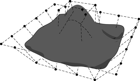
Figure 1. Schematic diagram of NURBS surface.
In Eq. 1,
The blade roughness of the integral impeller model is 0.4, and the roughness of other parts is 0.8. By using the parameter function in UG software to partition the mesh, mesh surfaces can be generated. The point set function is utilized to select points on the grid and convert them into point coordinates using an NX. grx file. Table 1 shows the coordinates of some blade root and top lines.
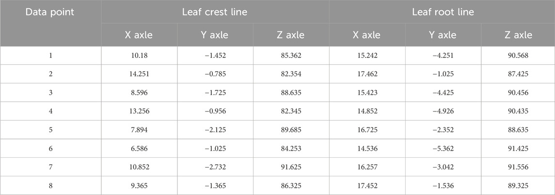
Table 1. The coordinates of the root line and the top line of the blade.
The fitting curve of the data points is an interpolation curve. This study used NURBS interpolation to fit data points to form the blade baseline. Firstly, to generate NER using UG software, divide the mesh into surface patches, and represent the data points on them in the form of coordinates. Using MATLAB software to reverse calculate control points and node vectors, while generating blade curves. Surface patches were obtained by connecting the corresponding points of the blades, and finally to evaluate the continuity and smoothness of the blade model. Assuming a NURBS curve has
In Eq. 2,
In Eq. 3, the tangent vectors of the starting and ending breakpoints are
A NURBS cubic open curve requires two boundary conditions to meet the requirements, with a repeatability of 4. The solution process of control point inverse calculation is carried out by calculating node vectors using MATLAB software and parameterizing data points through CCLP. Finally, the control points are back calculated using tangent boundary conditions, ensuring that the fixed value points and the initial and final endpoints of the control vertices coincide. Curve fitting is obtained through the theory of generating ruled surfaces. The surface smoothness check is obtained through the built-in lighting and curvature check methods of UG software. Previous studies have focused on local path optimization, without approaching the envelope surface and transforming the tool path planning problem into a tool path optimization problem under a single tool path (Ladj et al., 2021; Weckx et al., 2022). This study will take side milling as an example for analysis, and the definitions of tool position, design surface, envelope surface, and blade offset surface are as follows. The tool position refers to the trajectory formed by the movement of the tool’s upper points during the milling process. The tool axis and tool center jointly determine the position of the tool in space. The surface design is the impeller blade surface, which is a NURBS surface. The envelope surface refers to the trajectory surface obtained through the control of CNC-MT related programs. Blade offset surface refers to a design surface that is offset by a tool radius in the forward direction. The method for determining the initial tool position and posture in this study is the three-point offset method. For the principle error of NER S, this study established an error determination function. The tool axis is discretized by setting the point on the tool axis as
In Eq. 5, the distance between different positions on the tool axis and the design surface is
In Eq. 6, the position and attitude of the tool axis are
The optimal tool position posture is the minimum sum of the squared distances from any point on the tool axis to the tool surface and the design surface. The foot drop point
In Eq. 8, the tangential vectors of point
Given the complexity of traditional solving methods for the trajectory planning model of side milling cutter axes, this study proposes to use the SA-PSO fusion algorithm to solve the model. The core of the SA algorithm is that there is no rule that the recently generated solution is better than the current solution. The SA algorithm originated from the solid-state annealing process. Solid annealing is the process of first heating a solid to a certain temperature, then slowly lowering the temperature of the solid to make the particle arrangement inside the solid more uniform, thereby changing the properties of the solid. The SA algorithm first sets an initial temperature, and as the temperature continues to decrease, it stays at each temperature and accepts new values. Combined with probability jumps, it continuously optimizes. The SA algorithm can cross the current optimal value to find the global optimal solution, requiring a large solution space, weak local search ability, and multiple iterations. This method can effectively solve the problem of difficulty in obtaining global optima due to the rapid convergence of population individuals, reflecting its advantage of easily getting rid of local minima. PSO is based on social information sharing and achieves rapid convergence by comparing the current individual’s fitness with the historical optimal fitness, comparing the current fitness with the global optimal fitness. But it is prone to rapid convergence and stagnation in the later stage (Tao et al., 2022; Chinthamu and Karukuri, 2023; Kumar et al., 2023). In view of this, this study proposes an optimization method based on SA-PSO. This method first utilizes the global convergence of SA, and then combines the fast local search ability of PSO to determine the optimal position of the tool axis. Figure 2 is the flowchart of the SA-PSO algorithm.

Figure 2. Flowchart of SA-PSO fusion algorithm.
The core of SA is the Monte Carlo criterion, and the current minimum value criterion can be represented by Eq. 9.
In Eq. 9, the probability of accepting a new solution is
In Eq. 10, the function values of the current solution and the new solution are represented by
In Eq. 11,
In Eq. 12,
The population size of SA is 100, with a minimum and maximum temperature of 0.01 and 1,000, respectively, and a cooling rate of 0.9. The temperature decreases 10 times per iteration, and the constraint is to generate a sphere with a radius of 2 mm. Random perturbations are independent variables, i.e., particle positions. The center is the coordinate of the center of the ball on both sides of the tool axis. In the PSO algorithm, the particle motion speed is 1, the learning factor is all 1.5, and the maximum number of iterations is 100. During the machining stage, different positions on the tool axis constantly change at the vertical points of the design surface, and the normal vector is also constantly adjusted accordingly. The TES formed by processing is
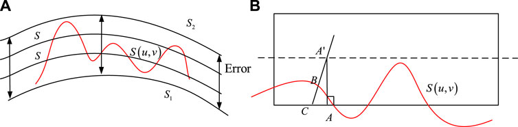
Figure 3. Error diagram of cylindrical cutter side milling envelope and calculation of side milling machining error. (A): Error diagram of cylindrical cutter side milling envelope; (B): Calculation of side milling machining error.
The tool sidewall and design curve
The calculation of envelope error is carried out by making a perpendicular point towards the design surface
The original data of the blades in this study was obtained from a certain enterprise’s integral impeller. A single blade was divided into 10 blade surfaces, and the third blade surface was selected as an example. The parameters include the wires and busbars of the curved surface. Select 8 tool positions uniformly on the second curved surface, and select eight points uniformly on the axis in the direction of the generatrix as the judgment positions for error measurement. Simulate using a column cutter with a diameter of 6 mm. Figures 4A,B show the control points for the top and bottom wires in NURBS, respectively.
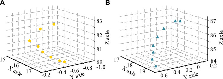
Figure 4. Control points of top and bottom traverse in NURBS. (A): Top wire; (B): Bottom wire.
Figures 5A,B show the training curves for single blade position SA and SA-PSO, respectively. In Figure 5A, it can be seen that under the control of the PSO algorithm, after 25 rounds of training for a single tool position, it repeatedly falls into the local optimal solution, with stable error values of 1.210, 1.302, and 1.345, respectively. Figure 5B shows that after adjusting the error using the SA-PSO algorithm, a single tool position avoids the phenomenon of getting stuck in local optimal solutions multiple times. The final value range is −0.416 to 0.421. In the subsequent training process, it is necessary to increase the maximum step distance of a single step and reduce the cutting amount of the tool under some training times. The result of a single tool path has certain significance for the final ITB CNC machining technology, as it can directly determine the machining quality of ITB and the operating efficiency of the tool.
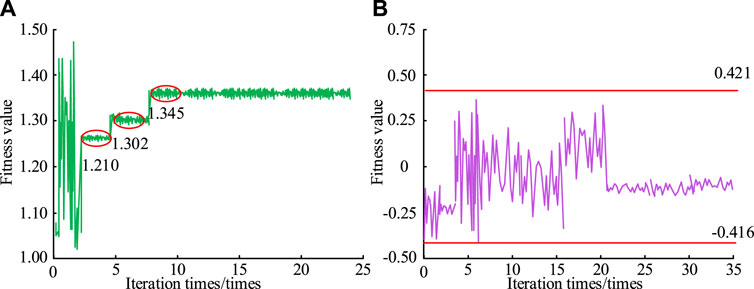
Figure 5. Trapping into local optimum and avoiding local optimum are two training curves. (A): PSO; (B): SA-PSO.
Figures 6A,B show the optimization results and optimization time of PSO and SA-PSO algorithms at different iteration times, respectively. As the number of iterations increases, the error values of both PSO and SA-PSO algorithms gradually decrease, with convergence times of approximately 7 and 6, respectively. The stable error value of SA-PSO algorithm is 0.253, which is 30.45% lower than PSO algorithm. For optimization time, the stable values of PSO and SA-PSO algorithms are 3.2 and 3.3 s, respectively. This indicates that although the iteration process of SA-PSO algorithm is not as fast as that of a single PSO algorithm, it is still within a reasonable numerical range and the numerical difference is not significant. Therefore, due to the significant advantage of the SA-PSO algorithm proposed by the research institute in terms of error value and the smaller difference in running time compared to the PSO algorithm, the overall performance is better.
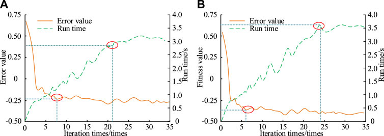
Figure 6. Optimization results and optimization time of PSO and SA-PSO under different iterations. (A): PSO; (B): SA-PSO.
Figure 7 shows the envelope error diagram of the tool at its initial position When the tool is in its initial position, the range of envelope error is −0.5 to 0 mm. This indicates that there is a situation of over cutting between the design surface and the tool. Therefore, the design surface needs to be adjusted through numerical algorithms to match the actual motion trajectory.
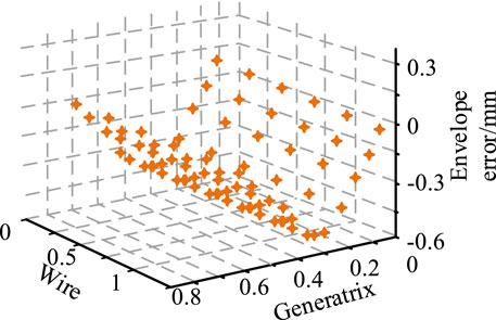
Figure 7. Envelope error diagram of tool in initial position.
Figure 8 shows the impact of different algorithms on the calculation results of envelope errors. Figures 8A,B show the single tool position envelope error diagrams for PSO and SA-PSO algorithms, respectively. In Figure 8A, the range of envelope error values is −0.018 to 0.018 mm. The results of the single tool position envelope error graphs for both SA-PSO algorithms show that the range of envelope error values is −0.01 to 0.01 mm. Therefore, after optimizing the trajectory model of the side milling cutter axis using two algorithms, the relationship between the design surface and the tool is still distributed between the over cut and undercut states. However, the SA-PSO fusion algorithm has significantly reduced the envelope error after optimization.
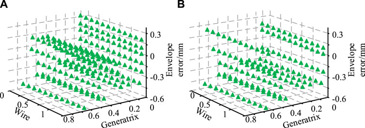
Figure 8. Influence of different algorithms on the calculation results of envelope error. (A): PSO; (B): SA-PSO.
Table 2 shows the envelope error of the single tool path for PSO and SA-PSO algorithms. When the calculation reaches the 7th iteration, both optimization algorithms have reached the optimal solution. The range values of PSO and SA-PSO algorithms are 0.0213 and 0.0165 mm, respectively. The range mean of the SA-PSO fusion algorithm is reduced by about 15% compared to a single optimization algorithm.
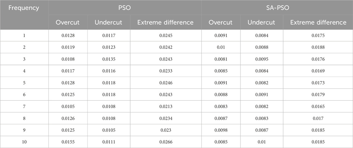
Table 2. Envelope error of single tool position of PSO and SA-PSO algorithms.
Figures 9A,B show the top and bottom positions of the initial and SA-PSO optimized tool axis trajectory surfaces, respectively. The tool axis trajectory surface optimized by SA-PSO is closer to the actual trajectory, and the processed blades better meet the quality requirements of ITB. The initial and optimized tool axis trajectory surfaces exhibit significant errors in the Y-axis direction, which may be caused by CNC-MT. After optimizing the PSO algorithm through the SA algorithm, this method can effectively solve the problem of difficulty in obtaining global optima due to the rapid convergence of population individuals, and is easy to overcome the advantage of local minima.
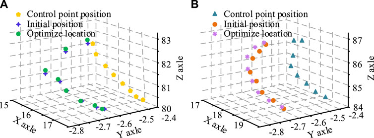
Figure 9. Initial tool axis trajectory surface and SA-PSO optimized tool axis trajectory surface. (A): Initial tool axis trajectory surface and SA-PSO optimized tool axis trajectory surface; (B): Bottom wire-Initial tool axis trajectory surface.
Figures 10A,B show the training results of using wire overlap as the target in both single and global cutting scenarios, respectively. Overall, after each training period, the sum of the normal and position mean squared deviations of the target model and the initial blank shows a large fluctuation range. The range of the sum of mean squared deviations for single and global cutting is 0.0011–0.0198 and 0.046–0.0341, but the overall error value is relatively small. This indicates that only some position target models match the normal direction, but the solution algorithm of the designed side milling cutter axis trajectory planning model can achieve good iterative operation results.
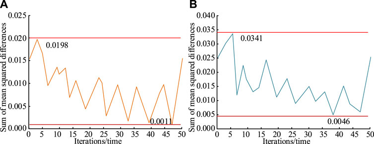
Figure 10. Target training results for single and global cutting scenarios. (A): Single cutting; (B): Global cutting.
To further validate the application effect of SA-PSO algorithm in lateral milling cutter axis trajectory planning, this study compared it with other similar studies, including references (Lu et al., 2022; Zhao et al., 2023; Zou et al., 2022). A comparison of the trajectory planning effects of the integral impeller side milling cutter shaft was conducted on a five axis machine tool model HS5AXIS 350, with indicators including average error and over cutting rate. The results are shown in Table 3. It can be clearly seen from Table 3 that the over cutting rate and machining error of the SA-PSO algorithm are 46.32% and 0.142 mm, respectively, and the required time is only 4.512 s. Compared with other studies, the SA-PSO algorithm has better efficiency and effectiveness in planning the axis trajectory of side milling cutters.
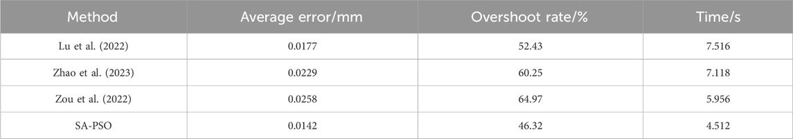
Table 3. Comparison results of lateral milling cutter axis trajectory planning.
The problem of deviation design between the design surface and TES when planning a single tool position. To solve the mathematical model through reasonable numerical methods to reduce computational complexity and improve operational efficiency, this study proposed to use the SA-PSO optimization algorithm to solve the trajectory planning model of the side milling cutter axis. After 25 rounds of training with a single blade position, it repeatedly fell into the local optimal solution, with stable error values of 1.210, 1.302, and 1.345, respectively. After adjusting the error through the SA algorithm, a single tool position avoided the phenomenon of getting stuck in local optimal solutions multiple times. The final value range was −0.416 to 0.421. For optimization time, the stable values of PSO and SA-PSO algorithms were 3.2 and 3.3 s, respectively. When the tool was in its initial position, the range of envelope error was −0.5 to 0 mm, and there was a situation of over cutting between the design surface and the tool. The range of single tool position envelope errors for PSO and SA-PSO algorithms was −0.018 to 0.018 mm and −0.01 to 0.01 mm, respectively. When the calculation reached the 7th iteration, both PSO and SA-PSO optimization algorithms had reached the optimal solution, with range values of 0.0213 and 0.0165 mm, respectively. The range mean of the SA-PSO fusion algorithm was reduced by about 15% compared to a single optimization algorithm. The tool axis trajectory surface optimized by SA-PSO was closer to the actual trajectory, and the processed blades better met the quality requirements of ITB. The target model at some positions matched the normal direction, but the solution algorithm of the designed lateral milling cutter axis trajectory planning model could achieve good operational results and find the optimal path with the minimum error in a fixed area. This study has shown good results in the field of principle error resolution, but there are still shortcomings. In the subsequent ITB CNC operation process, it is necessary to consider the impact of machine tool driven tool vibration and impeller defects on the actual effect.
The original contributions presented in the study are included in the article/supplementary material, further inquiries can be directed to the corresponding author.
YZ: Conceptualization, Data curation, Formal Analysis, Investigation, Methodology, Resources, Writing–original draft, Writing–review and editing.
The author(s) declare that no financial support was received for the research, authorship, and/or publication of this article.
The author declares that the research was conducted in the absence of any commercial or financial relationships that could be construed as a potential conflict of interest.
All claims expressed in this article are solely those of the authors and do not necessarily represent those of their affiliated organizations, or those of the publisher, the editors and the reviewers. Any product that may be evaluated in this article, or claim that may be made by its manufacturer, is not guaranteed or endorsed by the publisher.
Cheng, D. J., Zhang, J., Hu, Z. T., Xu, S. H., and Fang, X. F. (2020). A digital twin-driven approach for on-line controlling quality of marine diesel engine critical parts. Int. J. Precis. Eng. Manuf. 21 (1), 1821–1841. doi:10.1007/s12541-020-00403-y
Chinthamu, N., and Karukuri, M. (2023). Data science and applications. J. Data Sci. Intelligent Syst. 1 (1), 83–91. doi:10.47852/bonviewjdsis3202837
Fan, H. Z., Cao, Y. L., and Xi, G. (2020). Judging of machining feasibility and calculation of midsection for the five-axis milling of shrouded centrifugal impeller. J. Industrial Prod. Eng. 37 (7), 360–369. doi:10.1080/21681015.2020.1802620
Feng, J., Wei, Z., Wang, M., Wang, X., and Guo, M. (2021). Tool path planning for five-axis U-pass milling of an impeller. Int. J. Adv. Manuf. Technol. 117 (11-12), 3379–3391. doi:10.1007/s00170-021-07947-x
Franciosa, P., Sokolov, M., Sinha, S., Sun, T., and Ceglarek, D. (2020). Deep learning enhanced digital twin for Closed-Loop In-Process quality improvement. CIRP Ann. 69 (1), 369–372. doi:10.1016/j.cirp.2020.04.110
Guo, C., Chen, X., Li, Q., Ding, G., Yue, H., and Zhang, J. (2022). Milling optimization of GH4169 nickel–based superalloy under minimal quantity lubrication condition based on multi-objective particle swarm optimization algorithm. Int. J. Adv. Manuf. Technol. 123 (11-12), 3983–3994. doi:10.1007/s00170-022-10461-3
Guo, M., Fang, X., Hu, Z., and Li, Q. (2023). Design and research of digital twin machine tool simulation and monitoring system. Int. J. Adv. Manuf. Technol. 124 (11-12), 4253–4268. doi:10.1007/s00170-022-09613-2
Kiswanto, G. (2020). Digital twin approach for tool wear monitoring of micro-milling. Procedia CIRP 93, 1532–1537. doi:10.1016/j.procir.2020.03.140
Kumar, V. T. R. P., Arulselvi, M., and Sastry, K. B. S. (2023). Comparative assessment of colon cancer classification using diverse deep learning approaches. J. Data Sci. Intelligent Syst. 1 (2), 128–135. doi:10.47852/bonviewjdsis32021193
Ladj, A., Wang, Z., Meski, O., Belkadi, F., Ritou, M., and Da Cunha, C. (2021). A knowledge-based Digital Shadow for machining industry in a Digital Twin perspective. J. Manuf. Syst. 58 (1), 168–179. doi:10.1016/j.jmsy.2020.07.018
Liu, S., Lu, S., Li, J., Sun, X., Lu, Y., and Bao, J. (2021). Machining process-oriented monitoring method based on digital twin via augmented reality. Int. J. Adv. Manuf. Technol. 113 (1), 3491–3508. doi:10.1007/s00170-021-06838-5
Lu, Z., Yang, X., and Zhao, J. (2022). Tool-path planning method for kinematics optimization of blade machining on five-axis machine tool. Int. J. Adv. Manuf. Technol. 121 (1), 1253–1267. doi:10.1007/s00170-022-09271-4
Serin, G., Ozbayoglu, M., and Unver, H. O. (2020). Integrated energy-efficient machining of rotary impellers and multi-objective optimization. Mater. Manuf. Process. 35 (4), 478–490. doi:10.1080/10426914.2019.1605177
Tao, F., Xiao, B., Qi, Q., Cheng, J., and Ji, P. (2022). Digital twin modeling. J. Manuf. Syst. 64, 372–389. doi:10.1016/j.jmsy.2022.06.015
Tüchler, S., and Copeland, C. D. (2021). Numerical optimisation of a micro-wave rotor turbine using a quasi-two-dimensional CFD model and a hybrid algorithm. Shock Waves 31, 271–300. doi:10.1007/s00193-020-00979-4
Weckx, S., Robyns, S., Baake, J., Kikken, E., De Geest, R., Birem, M., et al. (2022). A cloud-based digital twin for monitoring of an adaptive clamping mechanism used for high performance composite machining. Procedia Comput. Sci. 200 (1), 227–236. doi:10.1016/j.procs.2022.01.221
Wei, J., Hou, X., Xu, G., Zhang, G., and Fan, H. (2021b). Modeling and machining of integral impeller based on NURBS curve. Int. J. Adv. Manuf. Technol. 113, 2243–2255. doi:10.1007/s00170-021-06704-4
Wei, Y., Hu, T., Zhou, T., Ye, Y., and Luo, W. (2021a). Consistency retention method for CNC machine tool digital twin model. J. Manuf. Syst. 58 (1), 313–322. doi:10.1016/j.jmsy.2020.06.002
Yan, Y., Zhang, L., and Gao, J. (2021). Tool path planning for flank milling of non-developable ruled surface based on immune particle swarm optimization algorithm. Int. J. Adv. Manuf. Technol. 115 (4), 1063–1074. doi:10.1007/s00170-021-07263-4
Yu, D. Y., Ding, Z., and Tian, X. Q. (2021). High-precision machining technology based on analytical method for integral impeller with flank milling. Int. J. Adv. Manuf. Technol. 114, 2309–2319. doi:10.1007/s00170-021-06931-9
Zhao, P., Liu, Z., Li, Z., and Cao, Z. (2023). Research on tool axis vector optimization when face milling complex surfaces. Int. J. Adv. Manuf. Technol. 128 (11-12), 5081–5099. doi:10.1007/s00170-023-12031-7
Zhao, Z., Wang, Y., Qian, N., Su, H., and Fu, Y. (2020). A framework for accuracy enhancement in milling thin-walled narrow-vane turbine impeller of NiAl-based superalloy. Int. J. Adv. Manuf. Technol. 108, 3925–3938. doi:10.1007/s00170-020-05554-w
Keywords: SA, PSO, integrated impeller, non expandable straight surface, NURBS
Citation: Zhao Y (2024) Optimization of machining path for integral impeller side milling based on SA-PSO fusion algorithm in CNC machine tools. Front. Mech. Eng 10:1361929. doi: 10.3389/fmech.2024.1361929
Received: 27 December 2023; Accepted: 21 May 2024;
Published: 07 June 2024.
Edited by:
Wan-Chun Chuang, National Cheng Kung University, TaiwanReviewed by:
Ding Zhang, Guangdong University of Technology, ChinaCopyright © 2024 Zhao. This is an open-access article distributed under the terms of the Creative Commons Attribution License (CC BY). The use, distribution or reproduction in other forums is permitted, provided the original author(s) and the copyright owner(s) are credited and that the original publication in this journal is cited, in accordance with accepted academic practice. No use, distribution or reproduction is permitted which does not comply with these terms.
*Correspondence: Yu Zhao, zhaoyu821122@163.com
Disclaimer: All claims expressed in this article are solely those of the authors and do not necessarily represent those of their affiliated organizations, or those of the publisher, the editors and the reviewers. Any product that may be evaluated in this article or claim that may be made by its manufacturer is not guaranteed or endorsed by the publisher.
Research integrity at Frontiers
Learn more about the work of our research integrity team to safeguard the quality of each article we publish.