 Bo Tang
- College of Electrical Engineering and New Energy, Three Gorges University, Yichang, China
Introduction: High-fidelity simulation of the radar echo from the wind turbine (WT) for accurate acquisition of Doppler features, is the key issue in addressing radiation interference from the wind farm on the nearby radar station. In view of the limitation of the conventional scattering center-based equivalent model to reflect the complex surface of blades, it is difficult to simulate the rotating blades’echo accurately with the existing algorithm. Therefore, we proposed a simulation method based on a 3D scattering center extraction to deal with it.
Methods: Therefore, we proposed a simulation method based on a 3D scattering center extraction to deal with it. First, the method of scattering center equivalence to blade scattering is used in order to reduce the modelling as well as the solution of electromagnetic scattering from the multi-space attitude of the blade, which is different from the existing algorithm. Since the geometry affects the parameters of the scattering center, an orthogonal matching pursuit greedy algorithm is used to extract the parameter of the 3D scattering center model.
Results: Therefore, the temporal correspondence between the scattering center and the blade motion characteristics is established, resulting in a reconstruction of the scattered field data of the rotating blades. Consequently, the real-time simulation and Doppler characteristic of blades echoes are achieved using the Short Time Fourier Transform (STFT).
Discussion: A comparison of the results with the data obtained from the GTD scattering center model verififies the accuracy of the proposed method.
1 Introduction
With the large-scale construction of wind farms in China, the interference from wind farms on adjacent radar stations are becoming more and more serious (He et al., 2017b; Steven et al., 2017). Engineering practice shows that with the stimulation of radar incident electromagnetic waves, the radar echoes scattered by WT blades possess micro-Doppler characteristics, quite different from static targets. Accordingly, the accurate acquisition of WT radar echoes to identify the wind farm targets for radar filtering is the key problem to calculate the interference on radar stations from wind farms.
The current methods for obtaining WT Doppler echoes can be divided into two categories, namely the experimental measurement and the numerical simulation (Pooria et al., 2017; He et al., 2021). Experimental measurement which is the most reliable is difficult to perform widely due to its high cost and rather complicated procedures (Chen, 2011; Crespo-Ballesteros et al., 2017). In consequence, increasing efforts have been devoted to the numerical simulation of WT Doppler echoes (Chen et al., 2017; He et al., 2017a).
The earliest numerical method adopt the scattering point model (Tang et al., 2019a; Tang et al., 2019b). However, as the discreteness of scattering point spacing is neglected, the obtained echo is too ideal to represent the real echo (Sun et al., 2016). The method of moments (MoM) can accurately calculate the echo by means of an accurate and intricate geometric model, but the calculation time and resources of MoM increase dramatically with frequency, which is unacceptable in the high-frequency band (Dunoon and Brown, 2013). With the aim of improving calculation efficiency, high-frequency electromagnetic algorithms (Tang et al., 2011; Yan et al., 2011) have been used to calculate the echo, such as the physical optics method (PO) (Zheng et al., 2020a), geometrical theory of diffraction (GTD) (Dai et al., 2020), and others that allow for very fast calculations. However, these. methods neglect the contribution of the edge’s diffraction field of the WT during the calculation. So the calculation results are in a poor accuracy, when solving such electromagnetic scattering problems of complex shaped surface like the WT blade.
From the present point of view, scattering centers are used in radar echo analysis of rotating targets such as missiles, which are introduced into the electromagnetic scattering solution of WT blades. In (Zheng et al., 2020b), the scattering center model was used to calculate the scattered electric field of WT blades, laying the groundwork for the solution of the echo. Then Tang et al. (Tang et al., 2019c) combined the GTD scattering center model with the radar echo equation to calculate the echo. Although the introduction of the scattering center provides new ideas for calculating the echo simulation, the calculation accuracy was still relatively low. That’s because the existing scattering center models are based on a two-dimensional plane for equivalent model reconstruction, so the existing equivalent models neglect the scattering center occultation and anisotropy caused by the geometric properties of WT blades (Gao et al., 2016). Therefore, the equivalent model built from the current scattering center model is too rough to represent the scattering properties from the actual shape of blades. As a result, the simulation results are quite different from the real echo, and the echo cannot be accurately obtained.
To address the problem that the conventional method is difficult to obtain accurate WT radar echoes, a new simulation method using scattering center parameters is proposed which could be considers the influence on the variation of from the blades’ three-dimensional geometric configuration. And then an echo simulation method based on 3D scattering center extraction is proposed to solve the anisotropy problem of the traditional scattering center model and finally achieve a high-fidelity echo simulation.
2 WT radar echoes and scattering center
2.1 Radar echoes of WT
The WT is mainly composed of three parts: tower, nacelle, and blades. The tower and nacelle are stationary parts and their echoes are zero-frequency components that can be easily filtered out using the high-pass filter. On the contrary, the rotating blades will generate complex electromagnetic scattering problems.
As shown in Figure 1, this is the process of the Doppler effect caused by WT blades, where dS is the scattering face element on the blades and v is the radial velocity vector. At a time of t1, wave 1 reaches the surface of the blades, at the same time the radar emits wave 2; at a time of t2, the radar receives an echo of wave 1, at which time wave 2 arrives the surface of the blades. Due to the rotation of the blades with the velocity of ω, there is a difference between the time when the radar receives the wave 1 and wave 2 echoes, making it possible to change the number of blade echoes received by the radar per unit time, thereby changing the frequency of the blades echoes. Therefore, the rotating blades will modulate the echo signal (Bo et al., 2016).
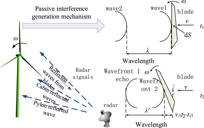
FIGURE 1. Schematic diagram of passive interference of WT to radar signal.
The modulated echo signal is affected by the radar observation point position, the complex heterogeneous surface of the blades, and the dynamic blade speed (Ding et al., 2017; Tang et al., 2017). So accurately obtaining the echoes of blades is a prerequisite for filtering out WT clutter.
2.2 Existing blades echoes simulation methods
At present, the numerical simulation algorithms of WT blades radar echoes mainly include integral algorithm based on scattering point model, scattering field algorithm based on precise geometry model, and integral algorithm based on scattering center. According to the results of echo simulation, the scattering point integration algorithm is simple to calculate. Yet, owing to the theoretical defects of the algorithm, the simulated echo lacks precision, and can only be used for qualitative analysis. The scattered field algorithm, although computationally accurate, relies on complex electrical large size models and a large number of calculations.
The integral algorithm based on scattering center is a new algorithm proposed in the literature (Zheng et al., 2020b) to overcome the defects of the above 2 algorithms. The mathematical model used in this algorithm is shown in Figure 2. The blade is rotated on the z-axis, the rotation plane lies in the xoy plane, the radar is located at point R, and the included angle between the radar incident wave and the blades rotation plane is φ = 0°. Considering that the blades of WT are electrode large size electromagnetic scatter, a scattering center model based on GTD was used.
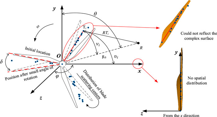
FIGURE 2. Diagram of integral algorithm based on scattering center.
The method equates the entire blades’ scattering entity as a series of scattering point sources by using the scattering field of the blades. And these scattering point sources are represented by the set of scattering center parameters. After the blades scattering center is obtained, the point target radar echo equation is introduced in literature (Zheng et al., 2020b) to simulate the blades radar echoes. Considering that the echo equation contains the position coordinates of the target point and the scattering intensity coefficient, only the position coordinates and the scattering intensity factor are applied to the echo equation.
In terms of the echo simulation process, the integral algorithm based on GTD scattering center discarded the scattering center type parameter αi when using the radar echo equation for echo simulation. Equivalence of complex curved blade to isotropic scattering center (Li and Du, 2017). Meanwhile, it is considered that the scattering center exists only in the xoy plane, ignoring the anisotropy of the scattering center caused by the 3D complex surface of the blades. Subsequently, the scattering center-based integration algorithm still lacks accuracy in the simulated echo signal.
2.3 Key steps to achieve accurate simulation of blades echoes
Starting from Section 1, it can be concluded that to accurately simulate the high-fidelity echo signal of dynamic blades, the following two 2 key problems need to be solved: firstly, the selection of a more accurate scattering center to accurately describe the scattering characteristics of a complex blade; and secondly, how to simulate a dynamic blade echo based on the dynamic scattering center.
Following electromagnetic scattering center theory, a complete scattering center dataset is required when the scattering center is used to equate a target scattering entity with a complex special shape structure (Li and Du, 2017). As a result, a length parameter L and type parameter αi will be introduced in this paper as quantitative indicators of the 3D geometry of WT blades compared to the traditional GTD scattering center model. Moreover, the 3D scattering center model based on physical optics and geometric diffraction theory is used to distinguish the various scattering structures of the blades, to realize the accurate characterization of the scattering characteristics of the blades.
On this basis, considering that the scattering center parameters of dynamic blades are closely related to the radar aspect, the rotation angle of the blade throughout its motion cycle is divided into multiple aspects, under which the 3D scattering center parameters of each aspect are solved. In addition, according to the idea of accurately solving the echo based on the scattered electric field, the obtained blades scattering centers are used to reconstruct the scattered electric field distribution corresponding to the real-time dynamic rotation of the blades, and the short-time Fourier transform is performed on the obtained scattered electric field vector. Finally, the real-time and fidelity simulation of blades echoes is achieved.
3 Simulation of WT blades radar echoes based on 3D scattering center
3.1 3D scattering center mode
According to the 3D scattering center model and the scattering characteristics of the blades, the total scattered electric field of the blades
where: fc is the central frequency of the radar electromagnetic wave; Li is the length of the scattering center, where is the localized scattering center when Li = 0 and the distributed scattering center when Li ≠ 0; γi is the orientation-dependent term of the scattering center, of order 10–10, which can be approximated to 0;
3.2 Extraction of 3D scattering center of WT blades
It is necessary to build a large parametric dictionary to estimate those parameters simultaneously. As the 3D scattering center includes eight target parameters and three radar parameters, the dimension of the parameterized dictionary is very high, which greatly increases the cost of computation and storage.
According to Eq. 1, the total scattering from blades in the frequency domain is a vector superposition of the electromagnetic scattering from multiple attribute scattering centers, so by creating an over-complete dictionary and dividing each column of the dictionary into an atom (a parameter set representing a scattering center), the total scattering from solid blades is a linear combination of these atoms. Firstly, let the dictionary D be given by the following equation.
where:
Due to
where: n, j is the number of parameters quantized
According to the principles of the OMP algorithm, after constructing the atomic dictionary, the problem of estimating the scattering center parameters is transformed into an optimal solution of the sparse representation, as follows.
where:
For the acquisition of the observed data
In the process of estimating the scattering center parameters using the OMP algorithm, it is considered that the performance of the OMP algorithm is disturbed by the scattering centers of neighboring WT blades. For this reason, the RELAX algorithm is introduced to correct the scattering center parameters calculated by the OMP algorithm for each iteration and to determine the termination conditions that satisfy the iterative process, then Eq. 5 is transformed into
The procedure for the joint solution using the OMP and RELAX algorithms can be found in the literature (Xie et al., 2019). Once the parameter set is obtained
3.3 Simulation process of WT echoes
After obtaining the scattering centers of all the blades, the scattering center parameters derived from the above steps
Where: ω is the angular velocity of the WT blades rotation; j is the jth sub-angle domain to which the rotating WT blades belong at moment t, where
On this basis, in order to achieve the time-frequency characteristics of the dynamic blade echo and Doppler characteristic analysis, the scattered electric field vector obtained needs to be processed by Short Time Fourier Transform (STFT), that is, there are
where: ∆t is the sampling interval associated with the amount of time, i.e. the scattered electric field under the reconstructed continuous time series is taken after each interval of ∆t time to facilitate time-frequency characterization; m, k, r = 0,1,2,3,..., (t/∆t-1), where t/∆t is the number of angular sampling points for the entire rotation period of the blades;
4 Verification of echo simulation method for 3D scattering center
The algorithm proposed in Section 2.1 for parameter estimation in terms of the scattering center of blade properties was compared with existing algorithms and the actual measurement experiments given in reference (Tang et al., 2019c) in order to verify the accuracy of the equivalent modelling of the blade 3D scattering center. Due to the fact that the actual measured wind turbine model and parameters are missing in the literature (Tang et al., 2019c), the typical Goldwind GW82/1,500 wind motor is taken as an example.
The full-size model of the blades and their position in relation to the radar is shown in Figure 3. To compare with the research results in the literature (Tang et al., 2019c), the incident Angle of radar electromagnetic wave is adopted by literature (Tang et al., 2019c), that is, the incident wave is set parallel to the blades rotation plane, the incident point is set on the y-axis, and the included Angle φ is 0° between the incident wave and blades rotation plane xoy. The initial frequency of electromagnetic wave f0 is 2.5 ghz, the center frequency fc is 3 GHz, the step frequency is 10 MHz, the bandwidth is 1 GHz, and the intensity is 1 V/m. The incidence direction of electromagnetic waves of radar is fixed and unchanged. Given the single blade length L of Goldwind GW82/1,500 wind motor is 41 m.
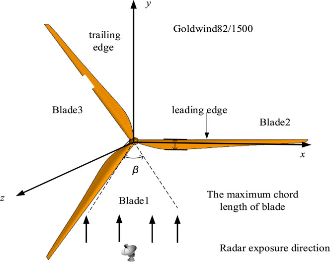
FIGURE 3. Geometry model of Goldwind82/1500 WT blades.
The electromagnetic scattering source data
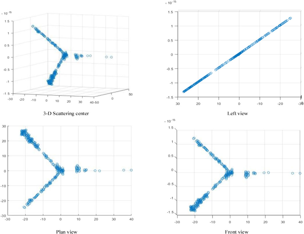
FIGURE 4. Equivalent model of the 3-D scattering center.
The 3D scattering centers of the blades are point-like or lamellar, including local scattering centers and distributed scattering centers. The uneven distribution of the scattering center is mainly related to the shape and structure of the blades, being densely distributed at the front and rear edges, axes and tips of the WT.
It is evident from Figure 4 that the estimated scattering center is consistent with the appearance profile of the body of the blades. However, as a further step towards a more accurate quantitative analysis of the equivalent modelling of the three-dimensional scattering centers of the blade, the GTD scattering center and 3D scattering center obtained were reconstructed respectively to obtain the scattering electric field distribution of the blades, using the FEKO simulation data as standard data. Figure 5 shows the error distribution of the scattering electric field reconstructed by the two scattering centers and the standard data.
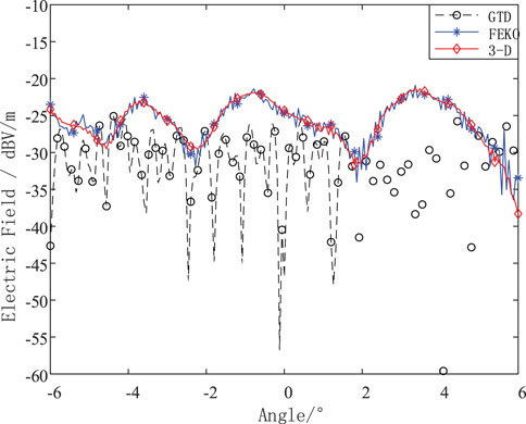
FIGURE 5. The distribution of the scattered electric field of the blade.
It can be seen from Figure 5 that the distribution of the scattering electric field reconstructed by the attribute scattering center is in good agreement with the original scattering electric field data simulated by the FEKO. While the distribution of the scattering electric field reconstructed by the GTD scattering center algorithm is in bad agreement with the original scattering electric field.
As can be seen from Figure 6, out of a total of 401 data, only 5 scattered electric field data reconstructed by attribute scattering center have an error of more than 3dB, while 144 scattered electric field data reconstructed by GTD scattering center have an error of more than 3dB, with a precision difference of 34.7%.
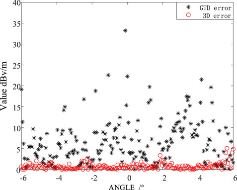
FIGURE 6. Distribution of scattered electric field error results.
It can be seen from Figure 6 that among the total 12,001 sampling points, there are 9,751 points with a difference less than 3 dB V/m, that is, the rotating WT scattering electric field reconstructed by the attribute scattering center method is 81.26% similar to the original data. The average error between the electric field data obtained by the algorithm proposed in this paper and the original electric field data obtained by Feko is 3.16 dB V/m. For the convenience of calculation while retaining the calculation accuracy, the value of 3 dB V/m is taken as the criterion for the accuracy of the algorithm. It shows that the extracted 3D scattering center can better replace the scattering characteristics of the real rotating WT, which verifies the correctness and accuracy of the equivalent modeling of the WT based on the 3D scattering centers.
The 3D scattering centers of the blades are point-like or lamellar, including local scattering centers and distributed scattering centers. Non-uniform distribution of scattering centers is mainly related to the shape and structure of the blade, with scattering centers of the blade densely distributed at the front and back. As described in Section 1.2 of the paper, the blades GTD scattering center is equivalent to the point-like scattering center shown in Figure 2 for the blades of a complex profiled surface, ignoring a large number of dihedral Angle reflections and straight edge reflections of the front and rear edges of the blades. And 3D scattering center model of leaf blades length, the curvature of the scattering entities such as quantitative three-dimensional structure, thus distinguishing the various scattering structures of the blade and allowing a more accurate description of the scattering effects of straight blades, so that the accuracy of the scattering field strength calculation using the three-dimensional scattering center method is much higher than that of the GTD scattering center.
5 WT blades radar echoes simulation and analysis
5.1 Echo simulation of WT blades
On this basis, the same blade model and its specific parameters as in Section 3.1 are used to obtain the corresponding scattered electric field data. We also set the rotation of the blades angular velocity for 2π/3 rad/s, the pulse repetition frequency PRF for 4000 Hz and the observation time t for 3 s, by using Equation 7 to process the scattered electric field data obtained via the method proposed in this paper and the traditional single-view scattering center method respectively, which can obtain the time-frequency characteristics. The radar echo with time-frequency characteristics are obtained and compared with the blades radar time-frequency echo maps obtained from experimental measurements, as shown in Figure 6.
Comparing Figures 7A,B, it is observed that the maximum Doppler frequency appears at the same time in the blade time-frequency echogram, and both appear in the zero frequency band with stronger energy. According to the literature (Zheng et al., 2020b), the maximum Doppler frequency of the simulated blade can be found to be consistent with the calculated value fdmax = 2fcωl/c = 1717.36 Hz.
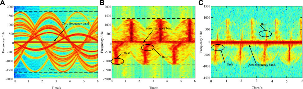
FIGURE 7. Comparison of time and frequency domain echo of blades obtained by different methods. (A)Integral algorithm based on scattering center, (B) proposed method, (C) measured data.
Meanwhile, the measured results in Figure 7C show that the time-frequency echo of the actual wind motor blades should also have the following characteristics: 1) positive and negative time-frequency flicker with energy difference; 2) time-frequency scintillation with bending phenomenon (Zheng et al., 2020b). These features are not shown in Figure 7A, but the simulation results of the proposed method are in complete agreement with the measured features.
The proposed algorithm uses a desktop computer, the CPU model is Intel(R) Core(TM) i5-9,500, the CPU frequency is 3.00GHz, the memory is 8GB, and the simulation software is matlab 2020B. The algorithm needs to complete the calculation of the scattering center for about 660 s. This algorithm can guarantee the calculation accuracy and simulate the radar echo of wind turbines without consuming a lot of computing time and computer memory.
5.2 Echo simulation analysis
An in-depth analysis of the Doppler characteristics shown in Figure 6B shows that for the Doppler characteristic of positive and negative time-frequency scintillation with energy difference appearing alternately in Figure 7B, combined with the analysis of the initial position of WT and the incident radar wave in Figure 3, it can be seen that when WT and the incident wave direction it is vertical, the effective irradiation range of the received electromagnetic wave will reach the maximum. In one rotation period, each blade will be vertically irradiated by electromagnetic waves twice, and the WT will have larger energy. As a result, the time-frequency echo of WT appears six times with energy difference in a single rotation period. The positive and negative alternating flicker is caused by the blades approaching or away from the incident electromagnetic wave.
The bending flash appears in Figure 7B and is due to the complex heterogeneous curved surface of the blade, considering the three-dimensional structure of the blade, so that the scattering energy provided by the blade surface is different when the electromagnetic wave is directed vertically at the front and rear edges of the blade. Combined with the 3D scattering center model, when the values of the scattering center parameter α and the length parameter L are different, the scattering forms of different structures can be characterized. Consequently, the time-frequency echoes obtained by the method in this paper shows the phenomenon of bending and flashing (Tang et al., 2021).
According to the above analysis, the proposed method in this paper can be seen to be superior to the traditional scattering center-based integration algorithm.
5.3 Analysis of generalizability
In engineering practice making full use of wind energy, the rotational plane of the WT blades will change accordingly with the wind direction of the natural wind, while the electromagnetic wave parallel to the blade rotational plane in Section 3.2 above belongs to a very special state, in most cases, there will be a certain angle between the radar incident electromagnetic wave and the blade rotational plane. Therefore, it is necessary to carry out echoes simulations of WT blades at different incidence angles β of the electromagnetic waves to further illustrate the universality of the method proposed in this paper.
Using the same blades model and radar parameters in Section 3.2, and setting the speed of the WT as π/3 rad/s,π/6 rad/s, π/12 rad/s, the radar echoes of the WT blades simulated by the method in this paper are shown in Figure 8.
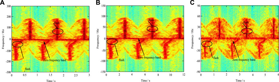
FIGURE 8. Comparison of time-frequency echoes of blades at a different speed. (A)Time-frequency domain of echoes with a frequency of 1 GHz and the speed of π/3 rad/s, (B) Time-frequency domain of echoes with a frequency of 1 GHz and the speed of π/6 rad/s, (C) Time-frequency domain of echoes with a frequency of 1 GHz and the speed of π/12 rad/s.
The maximum value of Doppler frequency in the blade time-frequency echo is 250 Hz, 125 Hz and 50 Hz respectively when the speed v is π/3 rad/s,π/6 rad/s, π/12 rad/s, as can be seen from Figure 8, and the sub-flash phenomenon gradually disappears. The reason for the above phenomenon is that, as the angle between the radar incident electromagnetic wave and the blades rotating plane increases, the incident electromagnetic wave in the blades rotating plane irradiation component gradually decreases, making the effective modulation effect of the blades on the incident wave decreases, thus finally leading to the blades’ maximum Doppler frequency of the time-frequency echoes is presented as a zero frequency band.
Conclusion
(1) Considering the hidden and anisotropic nature of the scattering center caused by geometric properties and rotation angle, an equivalent calculation model for the WT blades based on 3D scattering centers is proposed, which solves the problem that exists algorithms cannot accurately simulate echoes.
(2) Taking the GW82/1,500 as an example, the equivalent modelling accuracy of the blade scattering center is improved by 34.7% compared with the scattering center-based integration algorithm, achieving an accurate echo simulation and providing a theoretical reference for the next research on wind turbine array echoes.
Data availability statement
The raw data supporting the conclusion of this article will be made available by the authors, without undue reservation.
Author contributions
BT and HX participated in the design of this study, and they both performed the statistical analysis. GL carried out the study and collected important background information. LZ and ZS drafted the manuscript. All authors read and approved the final manuscript.
Funding
This work was supported by project Supported by National natural Science Foundation of China (51977121), Research Fund for Excellent Dissertation of China Three Gorges University (2021BSPY011).
Conflict of interest
The authors declare that the research was conducted in the absence of any commercial or financial relationships that could be construed as a potential conflict of interest.
Publisher’s note
All claims expressed in this article are solely those of the authors and do not necessarily represent those of their affiliated organizations, or those of the publisher, the editors and the reviewers. Any product that may be evaluated in this article, or claim that may be made by its manufacturer, is not guaranteed or endorsed by the publisher.
References
Bo, T., Bin, H., Li, H., and Jiawei, Y. (2016). “Radar echo signal simulation of wind turbine blades,” in 2018 IEEE International Conference on Applied Superconductivity and Electromagnetic Devices (ASEMD). 06 December 2018, (Tianjin, China: IEEE), 8–14. doi:10.1109/ASEMD.2018.8559006
Chen, Y., Li, S., Yang, J., and Cao, F. (2017). Rotor blades radar echo modeling and its mechanism analysis. Acta Phys. Sin. 65 (13), 138401. doi:10.7498/aps.65.138401
Crespo-Ballesteros, M., Antoniou, M., and Cherniakov, M. (2017). Wind turbine blade radar signatures in the near field: Modeling and experimental confirmation. IEEE Trans. Aerosp. Electron. Syst. 53 (4), 1916–1931. doi:10.1109/taes.2017.2675241
Dai, C., Huang, L., Tang, B., Liu, G., and Xie, H. (2020). “Simulation and characteristic analysis of wind turbine radar echo based on improved multipath model,” in 2020 IEEE International Conference on High Voltage Engineering and Application (ICHVE), 15 December 2020 (Beijing, China: IEEE), 2–24. doi:10.1109/ICHVE49031.2020.9279549
Ding, B., Wen, G., Yu, L., and Ma, C. (2017). Matching of attributed scattering center and its application to synthetic aperture radar automatic target recognition[J]. J. Radars 6 (2), 157–166. doi:10.12000/JR16104
Dunoon, L. R., and Brown, A. K. (2013). Modeling methodology for computing the radar cross section and Doppler signature of wind farms. IEEE Trans. Antennas Propag. 61 (10), 5166–5174. doi:10.1109/tap.2013.2272454
Gao, Y., Li, Z., Sheng, J., and Xing, M. (2016). Extraction method for anisotropy characteristic of scattering center in wide-angle SAR imagery[J]. J. Electron. Inf. Technol. 38 (8), 1956–1961.
He, W., Shi, Y., Guo, S., Wang, X., and Wu, R. (2017a). Simulation on wind turbine radar scattering characteristics and its micro-Doppler analysis[J]. Chin. J. Radio Sci. 32 (1), 103–111.
He, W., Liu, A., Wang, X., Zhang, Y., and Chen, M. (2021). Modeling and analysis of wind turbine echoes for airborne array radar[J]. Syst. Eng. Electron. 43 (3), 666–675.
He, W., Wu, R., Wang, X., Guo, S., and Ma, C. (2017b). The review and prospect on the influence evaluation and interference suppression of wind farms on the radar equipment[J]. J. Electron. Inf. Technol. 39 (7), 1748–1758. doi:10.11999/JEIT161004
Li, T., and Du, L. (2017). SAR automatic target recognition based on attribute scattering center model and discriminative dictionary learning. IEEE Sensors J. 19 (12), 4598–4611. doi:10.1109/jsen.2019.2901050
Pooria, P., Louis, L. S., Margaret, C., Andrew, H., and Matthew, F. (2017). Multipulse adaptive coherence for detection in wind turbine clutter[J]. IEEE Trans. Aerosp. Electron. Syst. 53 (6), 3091–3103. doi:10.1109/TAES.2017.2727825
Steven, I. K., Monica, M., Vincent, A., and Paul, B. (2017). Wind turbine interference mitigation using a waveform diversity radar[J]. IEEE Trans. Aerosp. Electron. Syst. 53 (2), 805–815. doi:10.1109/TAES.2017.2665143
Sun, H., Du, L., and Liang, G. (2016). Antenna model of MMC-HVDC converter valve system and its radiated electromagnetic disturbance analysis[J]. Proc. CSEE 36 (3), 879–888.
Tang, B., Chen, H., Huang, L., Yuan, F., Feng, P., and Li, Y. (2019c). Simulation and analysis of wind turbine blades radar echo based on electromagnetic scattering center[J]. Proc. CSEE 39 (24), 7375–7384.
Tang, B., Hao, B., Huang, L., and Yang, J. (2019b). Simulation of the Doppler echoes from wind turbine based on scattered electric field calculation. IET Radar,Sonar Navigation 13 (11), 2055–2062. doi:10.1049/iet-rsn.2018.5482
Tang, B., Hao, B., Zhang, J., Huang, L., Gan, Z., and Yang, J. (2019a). Simulation of wind turbine echoes based on electromagnetic scattering point spacing[J]. High. Volt. Eng. 45 (8), 2652–2661.
Tang, B., Liu, G., Xie, H., Huang, L., Dai, C., and Li, F. (2021). Radar echo simulation of dynamic wind turbine blade based on multi view attribute scattering center[J]. Proc. CSEE 41 (18), 6449–6460.
Tang, B., Liu, R., Zhang, J., Liu, X., Sun, R., and Jiang, H. (2017). Doppler characteristics of wind turbine blades based on dynamic RCS[J]. High. Volt. Eng. 43 (10), 3435–3442.
Tang, B., Wen, Y., Zhao, Z., and Zhang, X. (2011). Three-dimensional surface computation model of the reradiation interference from UHV angle-steel tower[J]. Proc. CSEE 31 (4), 104–111.
Xie, J., Liu, Y., Liu, L., Tang, L., Wang, G., and Li, X. (2019). A partial discharge signal denoising method based on adaptive weighted framing fast sparse representation[J]. Proc. CSEE 39 (21), 6428–6438.
Yan, H., Chen, Y., Li, S., Hu, L., Li, H., and Yin, H. (2011). A fast algorithm for establishing 3-D scattering center model for ship targets over sea surface using the shooting and bouncing ray technique[J]. J. Radars 8 (1), 07–116. doi:10.12000/JR18078
Zheng, X., Tang, B., Liu, G., Xie., H., and Dai, C. (2020). “Scattering electric field solution of wind turbine blade based on scattering center,” in 2020 IEEE International Conference on High Voltage Engineering and Application (ICHVE), 15 December 2020 (Beijing, China: IEEE), 1–4. doi:10.1109/ICHVE49031.2020.9279800
Zheng, X., Tang, B., Xie, H., Liu, G., and Dai, C. (2020). “Simulation and analysis of radar echo of wind turbine blades based on shooting and bouncing ray technique,” in 2020 IEEE International Conference on High Voltage Engineering and Application (ICHVE), 15 December 2020 (Beijing, China: IEEE), 3–34. doi:10.1109/ICHVE49031.2020.9279841
Keywords: wind turbine, wind farm, short-time Fourier transform, radar echo, three-dimensional scattering center
Citation: Tang B, Xie H, Liu G, Zhang L and Shang Z (2023) Radar echo simulation of dynamically rotating wind turbine blades based on 3D scattering center. Front. Energy Res. 11:1092673. doi: 10.3389/fenrg.2023.1092673
Received: 08 November 2022; Accepted: 17 January 2023;
Published: 03 February 2023.
Edited by:
Xin Ning, Institute of Semiconductors (CAS), ChinaReviewed by:
Imran Khan, University of Engineering and Technology, Peshawar, PakistanPrayag Tiwari, Halmstad University, Sweden
Copyright © 2023 Tang, Xie, Liu, Zhang and Shang. This is an open-access article distributed under the terms of the Creative Commons Attribution License (CC BY). The use, distribution or reproduction in other forums is permitted, provided the original author(s) and the copyright owner(s) are credited and that the original publication in this journal is cited, in accordance with accepted academic practice. No use, distribution or reproduction is permitted which does not comply with these terms.
*Correspondence: Huanghai Xie, 201908080011006@ctgu.edu.cn