- 1State Key Laboratory of Tea Plant Biology and Utilization, Anhui Agricultural University, Hefei, China
- 2School of Tea, Anhui Agricultural University, Hefei, China
- 3Anji Yuanfeng Tea Machinery Co. Ltd, Huzhou, China
- 4Anhui Intelligent Agricultural Machinery Equipment Engineering Laboratory, Anhui Agricultural University, Hefei, China
- 5School of Engineering, Anhui Agricultural University, Hefei, China
Introduction: The uneven heating of the U-shaped multi-groove pot in gas-fired tea fixation and shaping machines results in inconsistent quality of tea leaves.
Methods: A three-dimensional model of the gas-fired tea fixation and shaping machine was established by using SOLIDWORKS software. With the use of ANSYS finite element software, the orthogonal experiment method was applied to analyze and optimize the design of the spacing arrangement, the shape of the heating parts, and the heat conduction temperature field.
Results: Results show that the optimized heating parts significantly reduce the temperature difference on the surface of the U-shaped multi-groove pot, and the surface temperature field of the multi-groove pot is more uniform, which greatly improves the efficiency and quality of fresh tea leaf fixation and shaping. Prototype temperature and tea sample fixation ratio tests verified that the optimized heating components significantly improved the temperature uniformity of the U-shaped multi-groove pot and the quality of the finished tea.
Discussion: The research findings provide insights for further improving the uniformity of the U-shaped multi-groove pot’s temperature in the tea fixation and shaping machine.
1 Introduction
As the homeland of tea, China has a long history of tea culture and a variety of ways to develop the tea industry (Zhou and Zhang, 2024). In 2023, China’s tea output will be 3.55 million tons, and the output of green tea will reach 1.9 million tons, a year-on-year increase of 2.5%, accounting for more than half of the country’s total tea production. Fixation and shaping are important steps in green tea processing, and they directly affect the shape, quality, taste, and aroma of the tea (Xu et al., 2019; Wang et al., 2021). As the key equipment of these two processes, the gas-fired tea fixation and shaping machine mainly provides the temperature and force required in processing. During the operation of the gas-fired tea fixation and shaping machine, the heating parts provide the heat required by the U-shaped multi-groove pot, and the U-shaped multi-groove pot is driven by the crank slider mechanism to perform a horizontal linear reciprocating motion. The multi-groove pot and the tea leaves within it undergo relative motion, and under the effect of heating, the tea leaves gradually change shape, ultimately forming a strip (Jia, 2023). In this process, if the temperature difference on the surface of the U-shaped multi-groove pot is too large, then the quality of the tea sample in the same pot to be inconsistent, and red stems and red leaves, yellow leaves, scorched leaves, and old leaves will appear, which will affect the quality and efficiency of processed tea. Therefore, the temperature difference on the surface of the U-shaped multi-groove pot is one of the main indicators that affect the performance of the gas-fired tea fixation and shaping machine. The surface of the U-shaped multi-groove pot needs to have temperature uniformity (Yan et al., 2022). The main factors affecting the surface temperature difference of the U-shaped multi-groove pot include the arrangement and spacing of the heating parts, the shape of the heating, parts and the working environment temperature. Through comprehensive analysis and optimization of various influencing factors, the problem of uneven surface temperature of the U-shaped multi-groove pot can be effectively solved.
In recent years, scholars at home and abroad have studied the problem of uneven temperature of multi-groove pots extensively. Li (2020) found that the problems of large temperature difference and fast heat dissipation around the multi-groove pot could be solved by fast thermal conductivity of the oil. Thus, he set the fuel tank at the bottom of the multi-groove pot to improve the overall quality of fixation and shaping. Dai et al. (2018) developed a device that use electromagnetic heating technology to solve the problems of high energy consumption and large temperature difference in the traditional electric heating fixation and shaping machine. Adjusting the spacing between the electromagnetic and the multi-groove pot’s bottom surface, as well as the winding method of the coil effectively improved the temperature uniformity across the same cross-section during the heating process, enhancing the quality of tea fixation and shaping. Xu (2019) designed a halogen U-shaped heating tube with the function of adjustable arc. The spacing between the bottom of the multi-groove pot and the two ends of the heating part is smaller than the distance between the bottom of the multi-groove pot and the middle of the heating part, thus reducing the temperature difference between the surface of the multi-groove pot and achieving uniform heating of the tea.
In summary, the solution to the problem of uneven heating of multi-groove pot is mainly focused on changing the heating method and changing the structure of the heating parts. However, even though the heating component of gas-fired tea fixation and shaping machine is a relatively popular heating device, there is no practical and reliable way to ensure the uniformity of the surface temperature of gas-fired tea fixation and shaping machine of the U-shaped multi-groove pot.
Based on the theory of heat transfer and the orthogonal test method, this study started from the key factors such as the arrangement spacing and shape design of the heating parts, combined with ANSYS finite element simulation to optimize the temperature difference on the surface of the pot and tank (Yang et al., 2015), and verified the effectiveness of the optimization results through experiments, so as to improve the processing performance and tea quality of the gas-type finishing strip organizer. Finally, the temperature uniformity of the pot and the fixation moderate ratio before and after the optimization of the heating parts were compared, and the final results were obtained. The research results are helpful to significantly reduce the temperature difference of the U-shaped multi-groove pot during the operation of the equipment, improve the quality of tea making, and also provide a theoretical basis for the design and optimization of the tea fixation and shaping machine.
2 Materials and methods
2.1 Overall structure and working principle
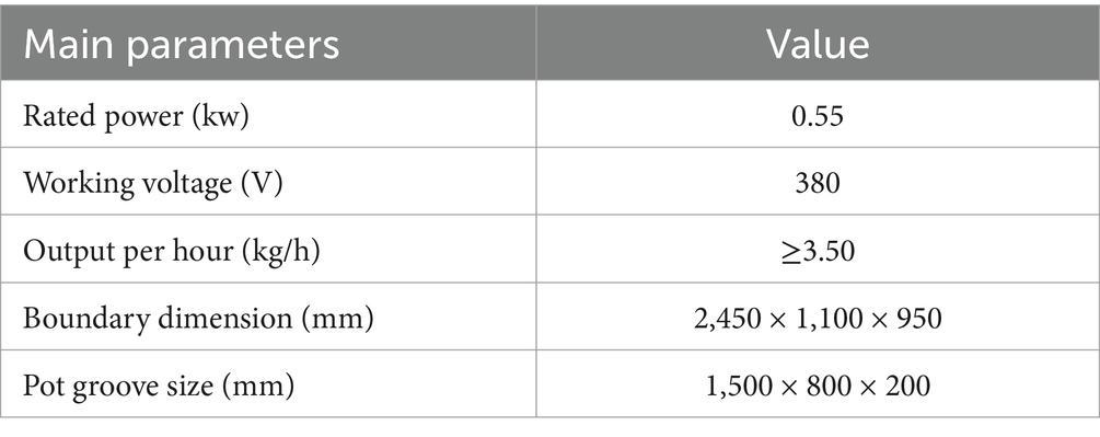
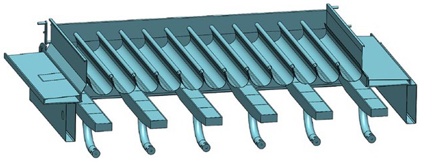
A 6CSL-800 gas-fired tea fixation and shaping machine is mainly composed of racks, U-shaped multi-groove pot, crank slider mechanism, motor, hydraulic cylinder, heating parts, furnace racks, gas regulating valve, gas transmission pipe, and other working parts (Bi et al., 2022). The overall structure is shown in Figure 1A. During the operation, the motor operates the crank slider mechanism to drive the U-shaped multi-groove pot to perform a reciprocating linear motion above the furnace plate. During the operation, the motor drives the crank slider mechanism to enable the U-shaped multi-groove pot to move back and forth in a straight line above the heating component. The tea leaves in the U-shaped multi-groove pot lose water and are shaped into a strip as they are heated and subjected to the back-and-forth driving force and friction (Luo et al., 2022b). As shown in Figure 1B, the furnace racks, heating part and the U-shaped multi-groove pot are collectively referred to as the fixation and shaping parts. The heating parts are equally distributed at the bottom of the U-shaped multi-groove pot, and the space between the two is the combustion chamber. The people manually adjusts the gas control valve through experience to control the gas intake of the heating parts to change the surface temperature of the multi-groove pot in different areas. The main technical parameters of 6CSL-800 gas-fired tea fixation and shaping machine are shown in Table 1.

Figure 1. Schematic of the structure of 6CSL-800 gas-fired tea fixation and shaping machine: Schematicof the overall structure (A). Schematic of the bottom structure (B).
2.2 Mathematical equalities
Two main heat transfer methods occur in the heat transfer mechanism of the multi-groove pot: heat conduction and heat convection. Specifically, the gas heating multi-groove pot process is achieved through the mechanism of thermal conduction, while the heat dissipation of the multi-groove pot edges to the environment relies on the mode of thermal convection. Heat conduction typically occurs between directly touching objects, provided there is a temperature gradient, or within an object where the temperature distribution is uneven (Jordan, 2019). Convective heat transfer occurs between a fluid and a solid surface or when there is not only a temperature difference but also relative motion between the two, serving as an effective means of heat transfer (Lu et al., 2018).
Through experiments, J.W. Biot proposed the following law in his study of heat conduction in a flat wall: the amount of heat conducted is inversely proportional to the thickness of the wall and directly proportional to the temperature difference on either side. On the basis of this principle, Fourier further delved into the core of the physical problem, thereby deriving the fundamental law that describes the process of heat conduction (Jia and Jia, 2009). The mathematical expression is shown in Equation 1:
where: represents the heat flux density, with units of J/(m2·s), and is the thermal conductivity of the material, which is related to the material of the thermal conductor, with units of W/(m·K). From this formula, the thermal conductivity of the pan and the heat flux density of the pan during the heat conduction process can be derived. In the Cartesian coordinate system, the components of the heat flux density in each coordinate axis can be represented by Equation 2:
The heat flux through a certain section perpendicular to the temperature gradient (area) is derived by using Equation 1:
If the temperature distribution inside the heat conductor is known, then the basic law of heat conductivity can be applied to calculate the heat flux density or heat flux of the heat conductor. The temperature gradient at a point on the surface of the pot can be expressed as Equation 1:
Figure 2A shows that when a multi-groove pot is heated, its thermal energy is only transferred between two isothermal lines or surfaces, that is, the area shown between the two isotherms t and t + dt in the figure. At any point P on the surface of the multi-groove pot, the direction of the temperature gradient is the same as the direction shown by n, which is the normal direction of the isotherm. During the operation of the U-shaped multi-groove pot, heat transfer occurs mainly during the contact between the flame of the heating part and the multi-groove pot. Once the heating component is ignited, the temperature difference between the flame and the multi-groove pot will promote the transfer of heat from the high-temperature zone to the low-temperature zone. Heat conduction is one of the main heat transfer methods throughout the heat transfer process.
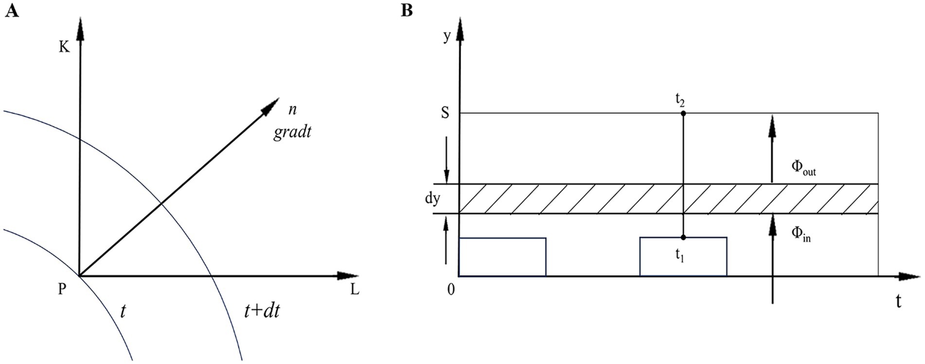
Figure 2. (A) Temperature gradient vector direction; (B) schematic of heat conduction in a multi-groove pot.
Figure 2B shows a schematic of the thermal conductivity of the side section of a U-shaped multi-groove pot. The area is represented by A, and the rectangular area is the location of the heating parts. The s in the figure represents the width of the U-shaped pot section; t1 and t2 indicate the temperature of both sides, respectively; dy represents the thickness of the microelement segment; and and represent the heat conductivity on the left and right sides of the microelement layer, respectively. According to the principle of conservation of energy in the closed control volume, can be derived. For heat conduction in the U-shaped groove, the amount of heat conducted on any cross-section within the U-shaped groove remains constant, denoted as (Liu et al., 2015). The temperature varies in the y-direction, and its temperature gradient can be expressed by Equation 5:
Equation 5 is integrated into Equation 3 to derive Equation 6:
According to , the following can be Equation 7:
In Equation 7, the cross-sectional area A and the thermal conductivity λ of the U-shaped multi-groove pot are constants. Equation 7 can be converted to Equation 8:
The general solution obtained by solving the differential equation is . Applying the temperature conditions , and , , on both sides of the U-shaped multi-groove pot can determine the coefficients and . Finally, the analytic expression of the internal temperature distribution of the U-shaped multi-groove pot is obtained, as shown in Equation 9:
As shown in Equation 10 the heat flux density through the cross-section of the U-shaped multi-groove pot is obtained according to the basic law of heat conduction (Equation 1), and the heat flux rate of the entire section can be obtained by multiplying the heat flux by the cross-sectional area A.
Heat convection is an important mode of heat transfer, where the movement of fluids plays a crucial role. It enables heat transfer through natural convection and can also be controlled and regulated through forced convection to meet different heat transfer requirements. Natural convection is a fluid movement caused by temperature differences and does not require external auxiliary forces. It is usually formed in a vertical or oblique direction and is affected by gravity. When a part of the surface of an object is heated, causing its temperature to rise, the air around that part is heated and the density decreases, creating an upward airflow. At the same time, the cooled air sinks, creating a convective circulation (Song, 2011; Li, 2016).
The basic formula for convective heat transfer is Newton’s law of cooling, which describes the relationship between the heat flux required to conduct heat in a fluid and the temperature difference, namely Equation 11:
where: is the amount of heat transferred through area A per unit of time; h is the convective heat transfer coefficient, which represents the amount of heat transferred between the fluid and the surface of the object per unit time per unit area; and is the temperature difference between the surface of an object and the fluid.
3 Temperature simulation
3.1 Establishment of the geometric model
As shown in Figure 3, the fixation and shaping parts were modeled in 3D. The basic size of this part is 1500 × 800 × 200 mm. The fundamental structure of a multi-groove pot is a slanted U-shape, with six fully equal and evenly spaced heating components placed 150 mm below, each with a length and width of 700 and 85 mm, respectively. The distance between the heating elements on both sides and the combustion chamber wall is 82.5 mm, and the distance between the heating parts is 165 mm.
The finite element simulation calculation was simplified by simplifying the 3D model of the whole machine accordingly, with parts other than the U-shaped multi-groove pot, stove frame, and heating part heating surface being removed (Luo et al., 2022a). As shown in Figure 4 the fluid domain used for the simulation calculation of the geometric model is extracted using SOLIDWORKS software. After being saved in.iges format, import fluid domains into Workbench 2022 R1 software for structured meshing. Finally, the mesh is exported for subsequent simulation calculations.

Figure 4. Fluid domain geometry extraction and meshing. (A) cross-sectional view of the simplified model; (B) extracted fluid domain model; (C) fluid domain meshing.
The thermodynamic simulation of the heating process in the fluid domain below the U-shaped multi-groove pot was carried out. The specific heat of the fluid domain is set to 1006.43 K, and the thermal conductivity is 0.0242 K. The temperature of the heating parts is set to 200°C, the ambient temperature is 22°C, and other environmental influences are negligible. After the various conditions and parameters have been set, the solution begins (Xue et al., 2022).
3.2 Analysis of the simulation results
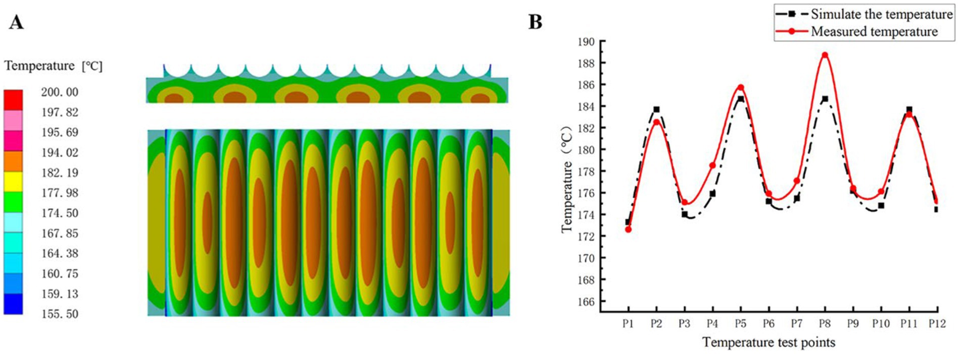
After the thermal analysis was solved, it was post-processed by ANSYS software to obtain thermal analysis maps of the upper and side surfaces, as shown in Figure 5A. As can be seen from the figure, the heating parts before optimization are evenly distributed at equal distances to heat the multi-groove pot, and the surface temperature distribution of the multi-groove pot is uneven. Specifically, the edge part dissipates heat quickly and the temperature is low. The center part dissipates heat more slowly, and the temperature is higher. The temperature difference was significant, with a maximum temperature of 194.02°C at the center and a minimum temperature of 167.85°C at the edge, indicating a difference of 26.17°C. The uneven temperature of the multi-groove pot will cause significant fluctuations in the quality of fixation and shaping during the actual fixation and shaping process, and local yellowing, scorched edges, or insufficient fixation and shaping of the tea will occur.
To verify the feasibility of the model for the analysis of the multi-groove pot temperature field, we randomly selected 12 positions on the simulated temperature contour map. At each position, three points with an equilateral triangle with an edge length of 1 mm were selected and inserted into the temperature probe, and the average temperature of the three points was obtained and calculated. In the same way, the temperature of the multi-groove pot at the selected point on the actual device was measured. The simulated temperature was compared with the measured temperature, and the results are shown in Figure 5B.
As can be observed from Figure 5B, the maximum temperature difference is 4.04°C at P8 and 0.23°C at P9. The temperature change trend is basically the same, and the temperature field obtained by simulation is basically consistent with the temperature distribution in the actual operation process. This result proves the feasibility and accuracy of the model.
3.3 Optimized design of heating components
Given the thermal exchange between the U-shaped multi-groove pot and the surrounding air, optimizing the arrangement and structure of the heating components is necessary to enhance the uniformity of the U-shaped multi-groove pot’s surface temperature.
The key influencing factors of the surface temperature difference of the U-shaped multi-groove pot include the shape of the heating element and its spacing layout. Other factors that affect this difference include the length of the heating part and the temperature of the operating environment. The orthogonal test method was used to design, compare, and analyze the experiment to systematically study the influence of these factors on temperature uniformity (Feng et al., 2022). The optimal process combination conditions can be determined through a limited number of tests.
3.3.1 Optimal design of the arrangement of heating components
The orthogonal test method can determine the optimal process combination conditions within a limited number of tests. Therefore, in this study, the orthogonal test method was used to optimize the arrangement spacing of the heating components. The goal of this experiment was to improve the temperature uniformity of the surface of the U-shaped multi-groove pot, thereby improving the quality of tea fixation and shaping.
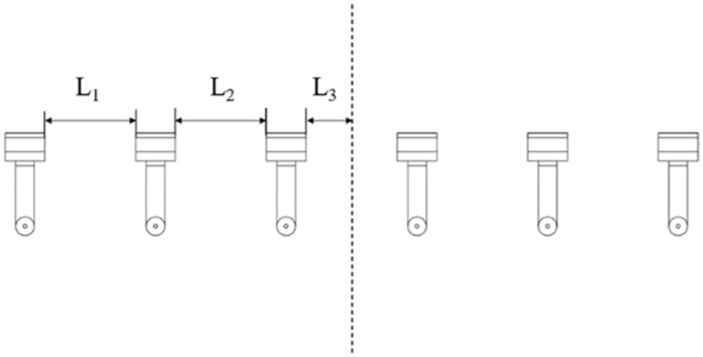
Considering the symmetrical nature of the temperature distribution of the heating part, only the right part of the heated part is analyzed (Yang et al., 2017). Three major optimization parameters were selected, namely, spacings L1, L2, and L3, between the heating components. The evaluation criterion of the test is the average temperature of the surface, where the average temperature is lower, indicates a better experimental effect. The relevant structural layout is shown in Figure 6.
3.3.1.1 Determining the level of factors affecting temperature differences
On the basis of the actual situation of the initial design and simulation, the spacings L1, L2, and L3 were selected as the test variables, and each variable was set to three levels, as shown in Table 2.
3.3.1.2 Orthogonal test results and analysis
On the basis of the factors and levels listed in Tables 2, a four-factor three-level orthogonal test was designed, and the L9 (34) orthogonal table was used to conduct the test. The combination of nine design variables was obtained from the orthogonally designed structural matrix, and the average surface temperature was obtained by ANSYS finite element analysis. The orthogonal test protocol and results are shown in Table 3.
The test results were processed by range analysis and obtained by processing the data by using MATLAB, as shown in Table 4. The influence of different factors on the average surface temperature is in the order of spacing L3 > spacing L2 > spacing L1. Depending on the size of the Ki, the optimal level for each factor can be determined. In this experiment, the goal was to make the experimental indicator as small as possible, which is why the level that made the smallest indicator was chosen as the optimum. Table 4 shows that the optimal level combinations of each factor are L1 (3), L2 (3), and L3 (1), and the corresponding levels are in parentheses, i.e., spacing L1 is 170 mm, spacing L2 is 175 mm, and spacing L3 is 97.5 mm.
3.3.1.3 Optimization results and analysis of the arrangement of heating components
Further simulations were carried out using ANSYS software, and the temperature distribution on the surface of the U-shaped multi-groove pot was obtained by applying the optimal parameters obtained from the orthogonal test and the range analysis. The temperature contour of this result is shown in Figure 7. Although the temperature difference between the middle and the ends does not change as much as it did before optimization, the area of the high-temperature section is significantly reduced, resulting in a more uniform temperature distribution on the XZ plane. However, in the Z direction, the temperature at both ends is still lower than at the other parts. The temperature at both ends of the multi-groove pot is low because the heating unit heats the multi-groove pot at both ends in the same way as the other positions. Therefore, further improvement is needed to improve this phenomenon.
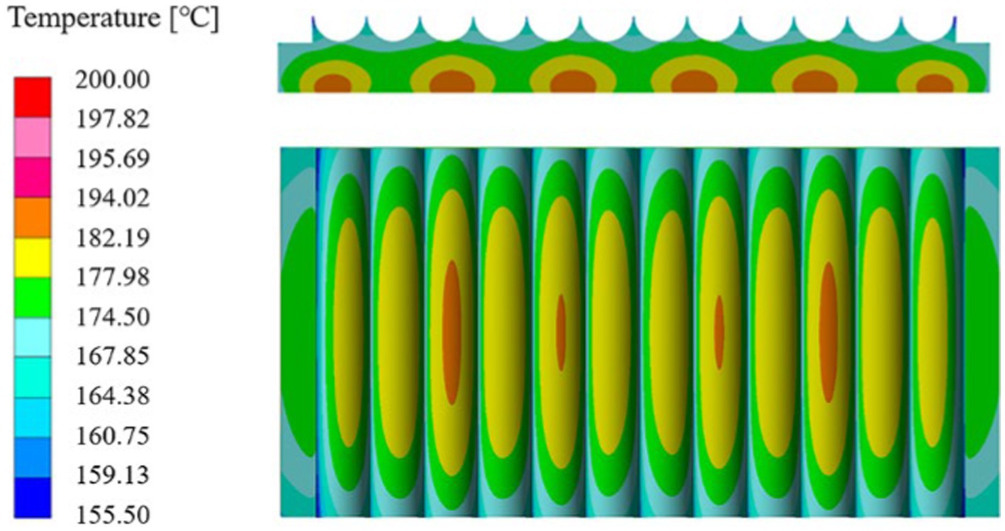
Figure 7. Temperature contour after optimization of the position distribution of the heating components.
3.3.2 Optimized design of the shape of the heating components
A large temperature difference still exists between the two ends and the middle of the multi-groove pot in the Z direction. Thus, the shape of the heating part is optimized into an “I”-shape while keeping the total air intake of the heating part unchanged, and the structural dimensions are shown in Figure 8A. The heating part spacing is 170, 175, and 190 mm using the above optimization results. The temperature distribution of the “I”-shaped heating parts with gradient arrangement is studied, and the temperature simulation results are shown in Figure 8B. The maximum temperature in the center is 190.12°C, the minimum temperature at the edge is 173.71°C, and the temperature difference is 16.41°C. Compared with the initial simulation results, the temperature difference between the middle and the edge is reduced by about 37.29%. This result shows that the U-shaped multi-groove pot maintains a relatively uniform temperature distribution even when it is affected by multiple factors during operation.
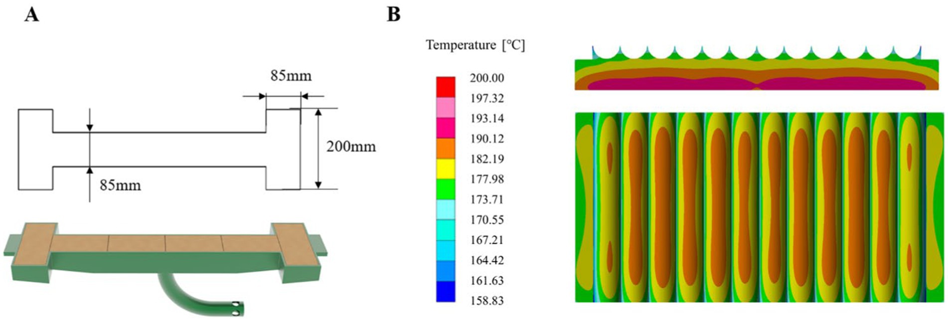
Figure 8. (A) Three-dimensional drawing of the “I”-shaped heating component; (B) temperature contour after the shape of the heating part was optimized.
4 Experimental validation
The performance of the machinery and equipment was tested during the tea picking season in April 2024 to confirm whether the optimized heating components effectively improve the temperature uniformity of the surface of the U-shaped pot and whether the processed tea products meet the quality standards of tea processing. In this experiment, the surface temperature of the U-shaped multi-groove pot before and after parameter optimization was measured and compared. The prototype before and after optimization was used to make green tea separately, and the fixation moderate ratio was used as the evaluation index for comparison. These tests aimed to evaluate the effect of the optimized heating components on the temperature uniformity of the fixation and shaping parts, as well as the effect on the quality of the finished tea.
4.1 Prototype temperature uniformity experiment
As shown in Figure 9B, a test platform with optimized parameters was first built according to the above optimization results. Optimized shape and distribution of heating components of test platform is shown in Figure 9A. The temperature test tool is an infrared thermometer as shown in Figure 9C, and the tea sample used in the test is Anji Baiye no. 1. A total of 12 temperature test points from P1 to P12 were selected according to the matrix arrangement, as shown in Figure 9D. An infrared thermometer was used to measure the temperature of each measuring point within a range of 10–15 cm from the surface of the multi-groove pot. Each measuring point was measured three times, and the average of the three temperatures was taken as the temperature of the point. Finally, the average of the temperatures of the three measuring points was taken as the effective operating temperature at that point on the multi-groove pot (Chen, 2010). The above tests were repeated three times to ensure the reliability of the data. The same method was used to measure the multi-groove pot temperature before optimization.
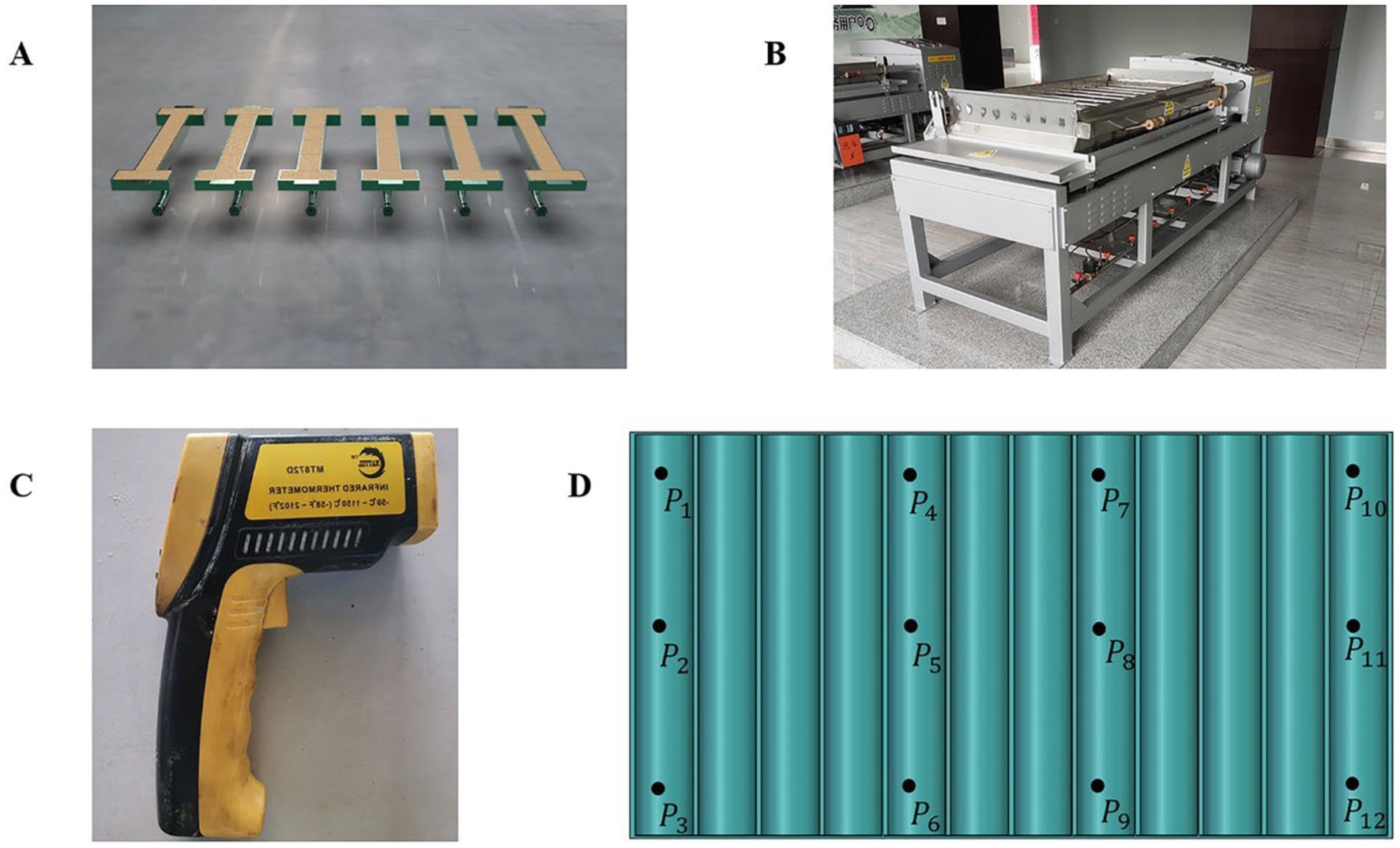
Figure 9. Schematic of test instruments, equipment, and test points: optimized shape and distribution of heating components (A). Optimized test platform (B). Infrared thermometer (C). Map of test points (D).
Figure 10 shows the average temperature values of the test results before and after optimization. The maximum surface temperature of the original U-shaped multi-groove pot was 192.8°C, and the minimum temperature was 168.4°C; the overall maximum temperature difference was 24.4°C, indicating poor temperature uniformity. After optimization, the maximum surface temperature of the U-shaped multi-groove pot was 188.2°C, and the minimum temperature was 172.8°C; the overall maximum temperature difference was 15.4°C, indicating a reduction by about 36.89%. Thus, the temperature uniformity of the U-shaped multi-groove pot was significantly improved after optimization. An important detail to note is that the test results may be affected by the test environment, test tool error, and human error. Nevertheless, the improvement of temperature uniformity after optimization is still obvious, indicating the effectiveness of the optimization measures.
4.2 Prototype fixation moderate ratio test
The fixation ratio was used as the test index for experimental verification to further verify the effect of multi-groove pot temperature uniformity on the quality of tea making, and the test site is shown in Figure 11. The withered tea leaves were poured into the multi-groove pot, and the motor speed was set to about 230 r/min in the fixation stage and 170 r/min in the shaping stage. The fixation and shaping process lasted for a total of 10 min. At the end of the fixation process, the 12 points of the temperature test above were selected to sample the dry tea samples in the pot, and 50 g was taken at each point, with a total sampling volume of about 600 g. The red-stemmed red leaves, yellow leaves, charred leaves, over-aged leaves, and moderately aged leaves were separated and weighed. The de-enzymed, moderately aged leaves have a green and lustrous color, with sharp edges becoming visible in the form of strip-like leaves. The formula for calculating the fixation moderate ratio is Equation 12:
where: Mr. is the fixation moderate ratio; Dq is the quality of dry tea that meets the quality requirements of fixation, kg; and M1 is the total mass of dry tea, kg.
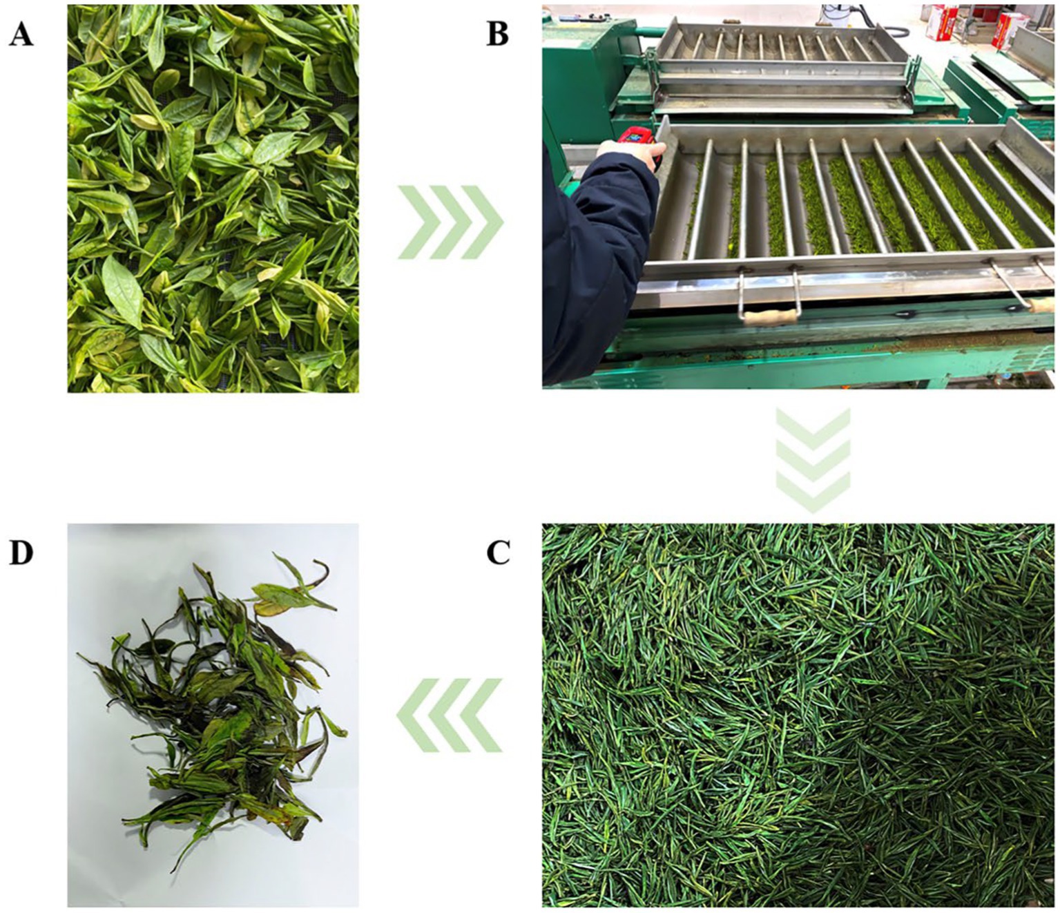
Figure 11. Fixation moderate ratios with the test flow: indoor withering (A). Test site (B). Qualified tea samples (C). Unqualified tea samples (D).
Three tests were conducted on the prototype before and after optimization, and the average value of the three groups of tests was taken as the final test result. The fixation moderate ratios in the first three experiments were 90.58, 92.31, and 87.89%, and the average value was 90.26%. The fixation moderate ratios in the three experiments after optimization were 93.18, 91.82, and 89.59%, and the average value was 91.53%. The results showed that the fixation ratio after optimization was better than that before optimization, and the quality of tea making was improved.
5 Results and discussion
1. ANSYS finite element software was used for simulation and analysis to solve the problem of uneven temperature of the U-shaped multi-groove pot of the gas-fired tea fixation and shaping machine. The results show that the key influencing factors for the large temperature difference on the surface of the multi-groove pot are the arrangement spacing of the heating parts and the shape of the heating parts.
2. The orthogonal test method and range analysis were applied to conduct finite element analysis of the arrangement and shape of the heating parts. When the heating part is I-shaped and the spacing is 170, 175, 190, 175, and 170 mm, the temperature difference of the U-shaped multi-groove pot surface decreases significantly. Thus, the efficiency and quality of fixation and shaping of fresh tea leaves are improved.
3. First, the surface temperature difference of the optimized multi-groove pot was tested by experiments. A comparison with the surface temperature difference of the optimized multi-groove pot showed that the overall maximum temperature difference of the optimized multi-groove pot was reduced by about 36.89% and the temperature uniformity was significantly improved, which confirmed the effectiveness of the orthogonal test optimization results. Second, fixation and shaping experiments were conducted with the fixation moderate ratio as the test index; the fixation moderate ratio was higher and the tea making effect was better after optimization.
The results show that the proposed optimal design of heating components can improve the uniformity of surface temperature and the tea making effect of the multi-groove pot, thus having high feasibility. This paper provides an idea to further improve the temperature uniformity of the multi-groove pot of the fixation and shaping machine.
Generative AI statement
The author(s) declare that no Generative AI was used in the creation of this manuscript.
Data availability statement
The raw data supporting the conclusions of this article will be made available by the authors, without undue reservation.
Author contributions
QW: Conceptualization, Data curation, Formal analysis, Investigation, Methodology, Software, Validation, Visualization, Writing – original draft. LY: Writing – original draft. CC: Investigation, Supervision, Writing – review & editing. KQ: Supervision, Validation, Writing – review & editing. YJ: Writing – original draft. YD: Software, Writing – original draft. XG: Data curation, Methodology, Writing – original draft. LF: Visualization, Writing – original draft. JZ: Writing – original draft. CF: Writing – original draft. HB: Conceptualization, Funding acquisition, Investigation, Methodology, Project administration, Resources, Writing – original draft.
Funding
The author(s) declare that financial support was received for the research, authorship, and/or publication of this article. This work was supported by Young Scientists Fund of the National Natural Science Foundation of China (No. 52205509) and Anhui Provincial University Natural Science Research Key Project (2024AH050444).
Conflict of interest
LY and YJ were employed by the Anji Yuanfeng Tea Machinery Co. Ltd.
The remaining authors declare that the research was conducted in the absence of any commercial or financial relationships that could be construed as a potential conflict of interest.
Publisher’s note
All claims expressed in this article are solely those of the authors and do not necessarily represent those of their affiliated organizations, or those of the publisher, the editors and the reviewers. Any product that may be evaluated in this article, or claim that may be made by its manufacturer, is not guaranteed or endorsed by the publisher.
References
Bi, H., Jia, P., Qin, K., Yu, L., Cao, C., and Bai, Y. (2022). Optimization Design of pot Slot Structure of tea De-enzyming and carding machine. Agronomy 12:2937. doi: 10.3390/agronomy12122937
Chen, C. (2010). Structure analysis and research on DriveSystem thermal error model of θFXZ typeCMMs. Tianjin: Tianjin University.
Dai, H., Ye, Y., Cheng, M., and Cao, J. (2018). Electromagnetic thermal carding machine structural design and testing. J. Green Sci. Technol. 14, 253–254. doi: 10.16663/j.cnki.lskj.2018.14.102
Feng, W., Liu, J., Hong, Y., Yang, B., Liu, M., and Lu, W. (2022). Orthogonal test method prefers film coating process parameters of hawthorn chewable tablets. Modern Food 28, 112–114. doi: 10.16736/j.cnki.cn41-1434/ts.2022.12.026
Jia, P. (2023). Influence of the pot groove structure of gas-fired tea de-enzymin-g and carding machine on the quality of Anji white tea. [master’s thesis]. Anhui: Anhui Agricultural Universit. doi: 10.26919/d.cnki.gannu.2023.000819
Jia, S., and Jia, X. (2009). Fourier and mathematization of theory of heat conduction. J. Dialectics Nat. 31, 65–112. doi: CNKI:SUN:ZRBT.0.2009-05-012
Jordan, H. (2019). Heat conduction: Methods, applications and research. New York, NY: Nova Science Publishers, Inc.
Li, Y. (2016). Investigation of heat transfer enhancement from straight-fin heat sink under natural convection. [master’s thesis]. Henan: Zhengzhou University.
Li, Z. (2020). A kind of automatic tea carding machine with uniform heating. Beijing: China National Intellectural Property Administration.
Lu, G., Gao, H., and Ma, X. (2018). Thermal engineering and fluid mechanic. Beijing: China Water and Power Pres.
Luo, K., Wu, Z., Cao, C., Qin, K., Zhang, X., and An, M. (2022a). Biomechanical characterization of bionic mechanical harvesting of tea buds. Agriculture 12:1361. doi: 10.3390/agriculture12091361
Luo, K., Wu, Z., Cao, C., Qin, K., Zhang, X., and Zhong, H. (2022b). Design and experiment of the combined pinch and cut picker for tea fresh leaf tips. Trans. Chin. Soc. Agric. Eng. 38, 1–9. doi: 10.11975/j.issn.1002-6819.2022.13.001
Song, W. (2011). Esearch on flow and heat transfer characteristics of AirForced convection cooling system in electronic Equipments. Hubei: Huazhong University of Science & Technology.
Wang, W., Song, Z., Chen, Q., Xiao, H., Jiang, H., and Zhang, J. (2021). Research progress of tea smashing machine in China. J. Chin. Agric. Mech. 42, 86–91. doi: 10.13733/j.jcam.issn.2095-5553.2021.02.013
Xu, X. (2019). A kind of carding machine heating mechanism. China patent application CN208863494U. Beijing: China National Intellectural Property Administration.
Xu, Y., Lu, W., and Lv, W. (2019). An empirical analysis of the impact of China′s tea export trade on the development of China′s tea industry. J. Tea 45, 185–192.
Xue, K., Gao, K., Kuang, F., Zhang, S., Liao, J., and Zhu, D. (2022). Machinery-plant-paddy soil coupling model based numerical simulation method of mechanical transplanting process of big rice seedling. Comput. Electron. Agric. 198:107053. doi: 10.1016/j.compag.2022.107053
Yan, J., Hu, D., Liu, Q., Yu, L., and Niu, S. (2022). Research progress and development trend of tea stripping technology and machinery. J. Chin. Agric. Mech. 43, 75–83. doi: 10.13733/j.jcam.issn.2095-5553.2022.02.011
Yang, B., Sun, B., Zhang, Y., and Wen, Y. (2017). Optimum design of bed temperature field of vulcanizing machine based on orthogonal test. Machinery 55, 78–82. doi: 10.3969/j.issn.1000-4998.2017.04.024
Yang, S., Yuan, R., Deng, L., and Ye, S. (2015). Optimization on the temperature field in thermal analysis furnace based on CFX. Mach. Design Res. 31, 158–161. doi: 10.13952/j.cnki.jofmdr.2015.0253
Keywords: gas-fired tea fixation and shaping machine, U-shaped multi-groove pot, temperature field, temperature difference, orthogonal experiment
Citation: Wu Q, Yu L, Cao C, Qin K, Jing Y, Dai Y, Guo X, Fan L, Zhang J, Fan C and Bi H (2024) Optimization and test of the heating parts of gas-fired tea fixation and shaping machine. Front. Sustain. Food Syst. 8:1510047. doi: 10.3389/fsufs.2024.1510047
Edited by:
Zhijian Tan, Chinese Academy of Agricultural Sciences, ChinaReviewed by:
Wuyun Zhao, Gansu Agricultural University, ChinaMingjiang Chen, Chinese Academy of Agricultural Sciences, China
Elçin Yeşiloğlu Cevher, Ondokuz Mayıs University, Türkiye
Copyright © 2024 Wu, Yu, Cao, Qin, Jing, Dai, Guo, Fan, Zhang, Fan and Bi. This is an open-access article distributed under the terms of the Creative Commons Attribution License (CC BY). The use, distribution or reproduction in other forums is permitted, provided the original author(s) and the copyright owner(s) are credited and that the original publication in this journal is cited, in accordance with accepted academic practice. No use, distribution or reproduction is permitted which does not comply with these terms.
*Correspondence: Haijun Bi, YmloYWlqdW5AYWhhdS5lZHUuY24=
 Qilong Wu
 Lei Yu3
 Kuan Qin