- 1Interactive Robotics Laboratory, School of Computing and Augmented Intelligence (SCAI), Arizona State University (ASU), Tempe, AZ, United States
- 2Corporate Functions-R&D, Procter and Gamble, Mason, OH, United States
We present WearMoCap, an open-source library to track the human pose from smartwatch sensor data and leveraging pose predictions for ubiquitous robot control. WearMoCap operates in three modes: 1) a Watch Only mode, which uses a smartwatch only, 2) a novel Upper Arm mode, which utilizes the smartphone strapped onto the upper arm and 3) a Pocket mode, which determines body orientation from a smartphone in any pocket. We evaluate all modes on large-scale datasets consisting of recordings from up to 8 human subjects using a range of consumer-grade devices. Further, we discuss real-robot applications of underlying works and evaluate WearMoCap in handover and teleoperation tasks, resulting in performances that are within 2 cm of the accuracy of the gold-standard motion capture system. Our Upper Arm mode provides the most accurate wrist position estimates with a Root Mean Squared prediction error of 6.79 cm. To evaluate WearMoCap in more scenarios and investigate strategies to mitigate sensor drift, we publish the WearMoCap system with thorough documentation as open source. The system is designed to foster future research in smartwatch-based motion capture for robotics applications where ubiquity matters. www.github.com/wearable-motion-capture.
1 Introduction
Tracking and estimating the human pose is essential for applications in teleoperation (Hauser et al., 2024), imitation learning (Fu et al., 2024), and human-robot collaboration (Robinson et al., 2023). To date, camera-based approaches are the gold standard for capturing human position and motion (Desmarais et al., 2021; Robinson et al., 2023). While purely optical motion capture solutions provide a high degree of accuracy, they are also subject to line-of-sight issues, which typically confines their use to controlled environments (Fu et al., 2024; Darvish et al., 2023). This requirement of controlled environments is even more prominent in human pose estimation advances in Virtual Reality (VR), and Mixed Reality methods (Walker et al., 2023), which typically require the user to wear VR headsets, or heavily rely on camera-based tracking.
The most prominent alternatives to optical solutions are based on Inertial Measurment Unit (IMU) sensors (Noh et al., 2024; Hindle et al., 2021). These methods employ customized IMU-based solutions (Prayudi and Kim, 2012; Beange et al., 2018; Li et al., 2021) on low-cost wearable embedded system (Raghavendra et al., 2017), possibly in fusion with optical methods for enhanceed accuracy (Malleson et al., 2017; Shin et al., 2023). Unlike optical methods, IMUs do not require a direct line of sight because they are directly attached to the user’s body. Commercial IMU motion capture systems incorporate up to 17 IMUs, enabling highly accurate non-optical human pose estimation (Roetenberg et al., 2009). Configurations with fewer sensors benefit from advances in deep-learning to obtain reliable lower-fidelity human poses (Huang et al., 2018). However, IMU-based motion capture systems typically require specialized IMU units and calibration procedures, thereby hindering their portability and applicability for inexperienced users (Huang et al., 2018; Roetenberg et al., 2009).
With the constantly growing popularity of consumer wearables, IMU-based motion capture from smartwatch and smartphone data offers perhaps the most ubiquitous solution (Lee and Joo, 2024). The recent IMUPoser (Mollyn et al., 2023) and SmartPoser (DeVrio et al., 2023) demonstrate that, even though consumer wearables motion capture may be less accurate than their optical and specialized IMU-based counterparts, these solutions are attractive because users tend to have these devices on them most of the time, enabling pose tracking at anytime and anywhere.
Despite these advances in ubiquitous pose tracking, smartwatch applications in robotics often merely utilize roll, pitch, yaw and gesture based control (Villani et al., 2020a), or on-body sensors for cognitive stress and alertness (Lee et al., 2015; Villani et al., 2020b). We have recently demonstrated the opportunities of motion capture from smartwatches for ubiquitous robot control (Weigend et al., 2023b; 2024). Under a fixed-body-orientation constraint, we showed that a single smartwatch facilitates teleoperation tasks (Weigend et al., 2023b). The additional sensor data from a smartphone in the pocket allows for tracking body orientation as well (Weigend et al., 2024; Weigend et al., 2023a). To foster future research in ubiquitous motion capture for robotics, in this work, we present WearMoCap—a comprehensive wearables-based motion capture system to unify and augment previous approaches in one system. As depicted in Figure 1, WearMoCap has three modes of operation for different levels of precision and portability. Improving on previous works, we benchmark WearMoCap extensively on three large-scale datasets, and show successful demonstration on multiple real-world robotics tasks.
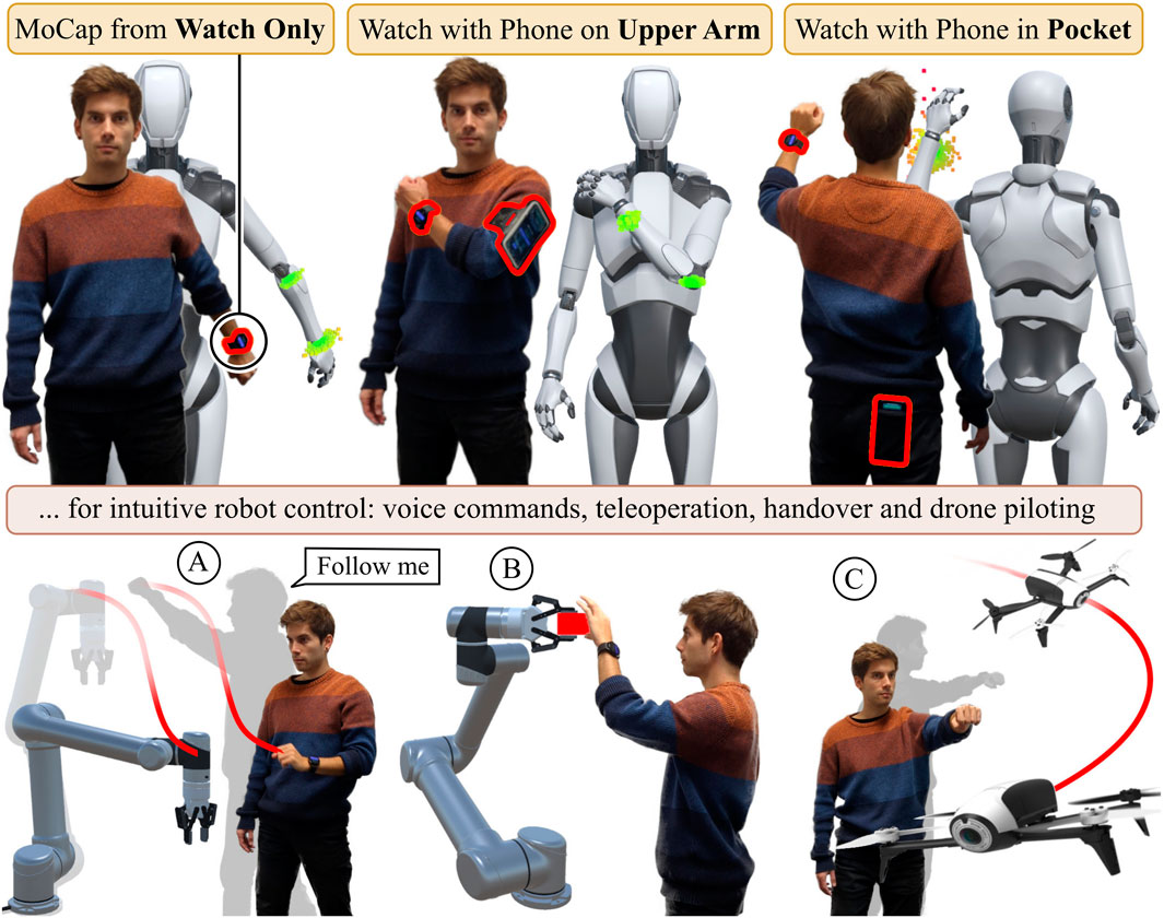
Figure 1. Our WearMoCap system features three modes: Watch Only requires a single smartwatch only. For Upper Arm we use a common fitness arm strap for the connected smartphone. The Pocket mode tracks the arm pose and uses the phone to determine changes in body orientation. We evaluate all modes in real-robot tasks, i.e., teleoperation, intervention (A), handovers (B) and drone piloting (C).
We publish WearMoCap as an open-source library, together with extensive documentation, as well as all our training and test data. Specifically, our contributions are.
• We unify previous and new pose tracking modalities, visualizations, and robot interfaces in one system under the name WearMoCap.
• We introduce a more precise Upper Arm pose tracking mode using an off-the-shelf fitness strap.
• We evaluate each system modality on large-scale datasets from a range of consumer devices, up to 8 human subjects, and by comparing them in real-robot tasks.
Overall, we envisage this paper to be a streamlined framework for wearable motion capture with three modes, intended to facilitate data collection and future research into human-robot interaction through smartwatch and smartphone motion capture.
2 Methods
This section introduces the system architecture and operation. Section 2.1 covers system modules and formalizes the data flow. Section 2.2 describes calibration procedures, followed by the methodology for each pose prediction mode described in Section 2.3. Finally, Section 2.4 covers additional control modalities that we use for our evaluation on real-robot tasks. Each section defines our contributions and additions to the methodology previous works.
2.1 System overview and architecture
WearMoCap streams sensor data from smartwatches and phones, and computes pose estimates using them for robot control. As depicted in Figure 1, the system operates in three modes: 1) The Watch Only mode produces arm pose estimates using the sensor data of a single smartwatch. 2) The Upper Arm mode further employs a smartphone strapped to the upper arm. The combined sensor data of watch and phone allow for more precise arm pose estimates. 3) The Pocket mode requires the user to wear the watch on their wrist and place the phone in any of their pockets. This allows for tracking both the body orientation and arm pose. While the Watch Only mode is based on Weigend et al. (2023b) and the Pocket mode on Weigend et al. (2024), the Upper Arm mode is introduced by this paper.
WearMoCap unites all three modes in one framework. To ensure that users can deploy and switch between WearMoCap functionalities easily, we developed WearMoCap as a modular system (Figure 2). The system consists of the following components: i) apps to stream sensor data to a remote machine, ii) a pose estimation module to transform received sensor data into poses, iii) a visualization module that renders pose estimates and distributions using a 3D avatar, and iv) an interface to the Robot Operating System (ROS) for robot control. The apps are written in Kotlin and require Wear OS and Android OS. Pose estimation and the ROS interface are written in Python, and the visualization utilizes Unity3D and C# scripts. The communication between modules is facilitated using UDP messages. The only exceptions are robot control, which uses a ROS topic, and communication from the watch to the phone app, which is realized via Bluetooth.

Figure 2. A schematic of the data streams between modules. The pipeline from smartwatch to visualization defaults to UDP. The pose estimation module can publish to the Robot Operating System (ROS).
The user initiates the data stream by pressing a button on the watch app. Messages from the watch app,
with
In the Upper Arm and Pocket modes, the watch streams
with
The pose estimation module receives
with
The reference frame for all final positions is relative to the hip origin. For estimating joint positions through forward kinematics, we facilitate default arm lengths and shoulder offsets. As shown in Figure 3, the default left shoulder origin relative to the hip was set to X: -17.01 cm, Y: 43.1 cm, Z: -0.67 cm, which was determined as an average from our first three human subjects. Moreover, the default upper arm and lower arm lengths were set to 26 cm and 22 cm respectively. These settings worked well for all our experiments but developers can easily adjust the defaults in the bone_map.py script in our repository.
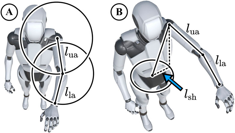
Figure 3. (A) Possible wrist and elbow positions around the shoulder lie on spheres with the radii of our standard upper arm length 26 cm
A local WiFi connection is sufficient to establish the connections between the devices, there is no requirement for internet connectivity. The device synchronization is maintained as follows: First, the watch sends its data to the phone, along with the associated timestamps. The phone maintains a queue to collect the timestamped data from the watch, and then collects its own sensor data at the fastest rate possible. Once the phone completes the collection of a new array of its sensor values, it processes the data in the queue from the watch. The phone integrates the watch data over time and aligns it with its own data. This way, the final output from the phone contains the most recent phone sensor data along with the integrated watch data, accurately matched to the corresponding time points.
2.2 Calibration
Motion capture requires a set of transformations to bring body joints and IMUs into the same reference frame. Traditionally, this involves calibration procedures like standing in a T-Pose (Roetenberg et al., 2009; Mollyn et al., 2023). We implement a seamless calibration pose for each mode, asking the user to hold a respective pose (as depicted in Figure 4) for one second.

Figure 4. All modes start with a one-second calibration pose. For Watch Only and Pocket mode the user holds their arm parallel to the hip. In Upper Arm mode the user stretches their arm forward.
For the Watch Only and Pocket modes, the user starts streaming with the watch app while holding their lower arm parallel to the chest and hip. The watch verifies this position using the gravity and magnetometer sensors. Then, it records the initial watch orientation sensor reading
Further, the watch records the initial atmospheric pressure
The calibration for the phone data operates similarly. In the Pocket mode, the phone orientation
We describe the detail of the calibration process along with the average duration for each mode in the following subsection.
2.2.1 Watch Only
The user has to hold the watch in a calibration pose as shown in Figure 4. The watch uses the gravity sensor to assess if it is positioned with its screen parallel to the ground. If the z-value of the gravity sensor is
2.2.2 Upper Arm
For this calibration procedure, the user has to complete two steps. Both are depicted in Figure 4. Step 1 is the same as Watch Only: If the z-value of the gravity sensor is
2.2.3 Pocket
The user places the smartphone in their pocket. The user holds the watch in front of their body as shown in Figure 4. Once the z-value of the gravity sensor is
2.3 Pose estimation in motion capture modes
This section outlines the pose estimation methodology for the three motion capture modes. All three modes employ neural network-based approaches with stochastic forward passes to obtain a distribution of solutions Gal and Ghahramani (2016). In Figure 5, possible solutions are depicted as small cubes colored according to their distance from the mean. Wide distributions are indicative of unergonomic arm poses or fast jittering motions.

Figure 5. Stochastic forward passes produce ensembles of possible arm poses. Individual predicted wrist positions are shown as dots, colored based on their distance from the ensemble mean—green indicates closer proximity to the mean, while red signifies greater deviation. High variance within the ensemble reflects high uncertainty, which might occur in unergonomic poses or during rapid movements. The true wrist position is indicated as ground truth (GT).
2.3.1 Watch only
For the Watch Only mode, we employ the derived optimal neural network architecture from Weigend et al. (2023b). An LSTM estimates the lower arm orientation
2.3.2 Upper arm
The previous Watch Only mode infers the upper arm orientation from the smartwatch sensor data only. This is sparse data for arm pose predictions. Therefore, we now introduce the additional Upper Arm mode, which facilitates more sensor data to infer the entire arm pose by placing the smartphone directly on the upper arm. As described earlier, the user can use an off the shelf fitness strap. We use an LSTM to predict
With this mode, after calibration, the user is free to turn around. However, this mode does not provide body-orientation estimates, which means the lower and upper arm orientations
2.3.3 Pocket
This mode is based on Weigend et al. (2024) and uses a Differentiable Ensemble Kalman Filter to update an ensemble of states from previous estimates and the watch and phone sensor data
2.4 Additional control modalities
For teleoperation tasks that involve advanced gripper control (see Section 3.4), we stream microphone data to issue voice commands. This is done by transcribing the recorded audio signal into voice commands utilizing the Google Cloud speech-to-text service1. We also implement two positional control modalities (A and B in Figure 7). Voice commands were used in our previous works (Weigend et al., 2023b; 2024) and Modality A was utilized in Weigend et al. (2023b), while Modality B was proposed in Weigend et al. (2024). Typically, users expect to control the robot with their hand position. Therefore, both of our control modalities translate wrist/hand positions into control commands, e. g., end-effector positions.
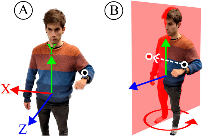
Figure 7. We use two control modalities to determine end-effector positions. Modality (A) leverages forward kinematics with default arm lengths to return the wrist origin relative to the hip. Modality (B) estimates the wrist origin projected onto the sagittal plane.
With Modality A, we determine the wrist position relative to the hip origin. This is then directly translated to the end-effector position relative to its base. Modality B requires the dynamic hip orientation estimates
The main difference between Modality A and B is the reduction in interacting degrees of freedom to reduce potential compounding errors. With Modality A, the end-effector X-position is determined by the complete kinematic chain
3 Results
We evaluate the performance of WearMoCap in real-robot tasks and on large-scale datasets from multiple studies and across multiple devices (smartwatches and smartphones). The first Section 3.1 covers the composition of our training and test datasets. Section 3.2 details prediction performance on our test datasets and compares it to related work; Followed by Section 3.4, which describes the evaluation on four real-robot tasks and concludes by summarizing results and limitations.
3.1 Composition of datasets
We composed a large-scale dataset by merging datasets collected from previous studies (Weigend et al., 2023b; 2024), and augmenting them with data collected for this study. We employed the following devices for data collection: smartwatches—Fossil Gen 6 Men’s, and Samsung Galaxy Watch 5 40 mm version (RM900) and 45 mm version (RM910); smartphones—OnePlus N100, TCL 40XL and Samsung Galaxy A23G. Out of these, only Samsung Galaxy A23G and Samsung Galaxy Watch 5 were used in the datasets from previous studies (Weigend et al., 2023b; Weigend et al., 2024). The rest are new to this study. The OS version on the Samsung Watches was WearOS 4 which is based on Android 13. The Fossil Gen 6 had WearOS3 based on Android 11. The sampling frequency of newer phones such as Samsung A23 is 90 Hz, while phone such as OnePlus N100 transmit data at 60 Hz sampling frequency. Since our model input includes delta time, the model is able to account for fluctuations and differences in frequency. For all previous and new datasets, the ground truth was obtained with the optical motion capture system OptiTrack (Nagymáté and Kiss, 2018). The OptiTrack motion capture environment featured 12 cameras, which were calibrated before data collection. Human subjects wore a 25-marker-upper-body suit along with the smartwatch on their left wrist and phone on upper arm or in pocket. We collected lower arm, upper arm, and hip orientations with time stamps. The system recorded poses at 120 Hz. In post processing, we matched WearMoCap data with the OptiTrack pose closest in time. All human subjects (8 Males; Mean age: 25
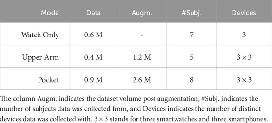
To collect data for the Watch Only mode, we asked subjects to perform single-arm movements under a constant forward-facing constraint. We combined this data with data from Weigend et al. (2023b), which resulted in a dataset with 0.6 M observations. Here, each observation refers to a collected data row.
For the Upper Arm mode, we asked 5 subjects to perform similar movements as above, but with a phone strapped on to their upper arm. For the Upper Arm mode, we did not enforce a constant forward direction. Additionally, subjects were encouraged to occasionally perform teleoperation-typical motions, such as moving the wrist slowly in a straight line. We showed demonstrations of writing English letters on an imaginary plane as examples of such motions. However, subjects were not strictly instructed to perform these movements and some chose not to or forgot. Therefore, not all recordings contained these teleoperation-typical movements. This resulted in a dataset with 0.4 M observations.
For the Pocket mode, subjects had to keep a smartphone in any of their pockets. For data collection, subjects were free to move their arm in any direction and without the forward-facing constraint. Further, the pose estimation in Pocket mode only requires the orientation sensor data
Both the Upper Arm and Pocket modes do not restrict body orientation, which allowed us to augment the data. This was done by rotating
For all the datasets, we provided the subjects with verbal instructions and brief demonstrations of motions that covered the position space well, and asked the subjects to perform them. We confirmed the variability of their motions by inspecting the 3D plots of their movement trajectories, which revealed that the data covers the position space. An example overview of all participant’s combined wrist positions is depicted in Figure 8. Our training and test data includes recording sessions of up to 10 min duration. The mean duration and other statistics such as number of sessions, average number of observations, etc. can be found in Table 2. Five of the subjects that were used to collect data in previous studies Weigend et al. (2023b), Weigend et al. (2024) were used again to collect new data in this study.
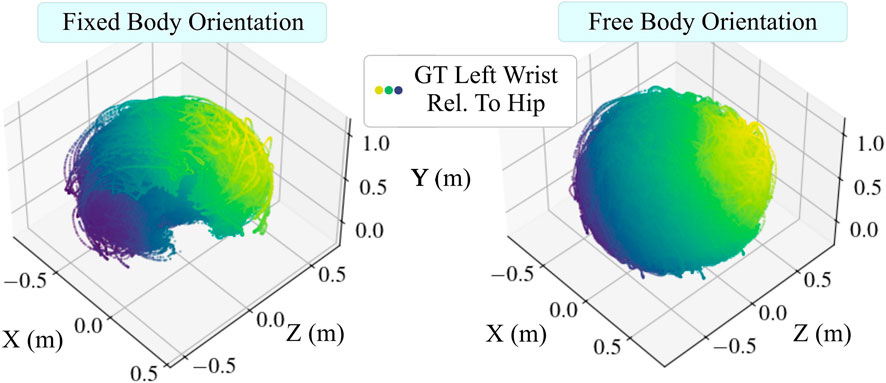
Figure 8. Using wrist positions as an example, this figure shows that our collected data covers the space of possible arm poses (position space). Dots are data points representing wrist positions relative to the hip obtained from the motion capture system, which also show differing arm lengths. Data points are colored according to the sum of their coordinate magnitudes. Left: Data points collected under the fixed forward-facing constraint. Right: Wrist positions collected without the fixed body orientation constraint form a full sphere.

Table 2. Statistics of dataset incorporated from previous works, and additional data collected in this work.
3.2 Model accuracy
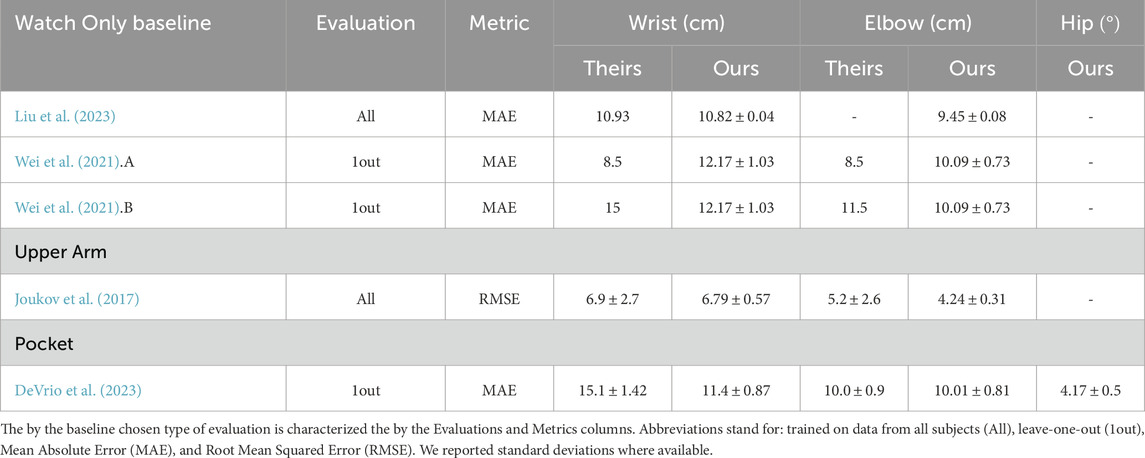
We employed our dataset to assess WearMoCap performance in two ways: all-subjects validation and leave-one-out validation. For the all-subjects validation, we utilized
3.2.1 Watch only
As depicted in Figure 6 (Left), we trained seven distinct models for the Watch Only leave-one-out validation corresponding to seven different subjects. On average, the predicted wrist positions deviated by
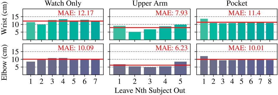
Figure 6. Euclidean Mean Absolute Error (MAE) of wrist and elbow position estimates in leave-one-subject-out cross validations. Specifically, we trained on data from all the subjects except the Nth subject, and tested on the Nth subject.
3.2.2 Upper arm
Similar to our Upper Arm mode, Joukov et al. (2017) proposes the use of one IMU on the lower arm and the second on the upper arm. Their evaluation is based on all-subjects validation and uses RMSE as the performance measure. Table 3 shows that our errors of
3.2.3 Pocket
Similar to our Pocket mode, the authors of DeVrio et al. (2023) also leveraged data from a smartwatch and additional sensor data from a smartphone placed in the pocket. The authors conducted a leave-one-out evaluation. A comparison of WearMoCap to their reported results is shown in Table 3, and also here are comparable. With an average wrist error of
All discussed methods are real-time capable. Our most computationally demanding mode is the Pocket mode, which achieves inference speeds of
3.3 Sensitivity analysis
To determine the relative importance of each input feature to our models, we conducted a sensitivity analysis where we left each sensor out, one at a time, in the Watch-Only mode. We noted effect on the model performance for prediction of Hand and Elbow positions in Table 4. The results show that leaving out the global orientation harms the performance the most, followed by gyroscope and accelerometer. While leaving out the atmospheric pressure sensor did not affect the accuracy significantly, we retained the sensor in our data.
3.4 Real-robot tasks
To assess the practical use of WearMoCap in robotics, we evaluate its application in four human-robot experiments, namely, Handover, Intervention, Teleoperation, and Drone Piloting tasks. The Handover and Intervention tasks were conducted for this work under the ASU IRB ID STUDY00018521. The Teleoperation and Drone Piloting tasks were conducted in Weigend et al. (2024) under the ASU IRB ID STUDY00018450. We picked these tasks such that our evaluation covers the three WearMoCap pose tracking modes Watch Only, Upper Arm, Pocket and control Modalities A and B with at least two experiments each. Section 3.4.5 discusses the results and compares them to the user performance with the OptiTrack system where possible. OptiTrack provides sub-millimeter accurate tracking and is therefore utilized as our state-of-the-art baseline (Nagymáté and Kiss, 2018; Topley and Richards, 2020). All human subjects (9 Males; 1 Female; Mean age: 25
3.4.1 Handover
In the Handover Task, an arm robot picks up an object from the table and hands it over to a human subject at a given location. Subjects sat on a rotating chair at a fixed location in front of a Universal Robot 5 (UR5). To do this task successfully, the robot must correctly track the human hand position. To this end, we provide the robot with the relative chair position, approximate sitting height, and arm lengths, such that it can estimate handover positions relative to its base.
As depicted in Step 1 on the left of Figure 9, the tabletop area between the robot and the subject was divided into three areas. We ask subjects to perform handovers in each of these areas to ensure a range of diverse poses. With the subject’s hand in one of these areas, the subject performed two handovers—once with the hand at a low height and once with the hand at a higher height. The subjects then repeated this task for all the other areas at random. The subject’s orientation was fixed for Watch Only mode, but for the other two modes, they could change their orientation by rotating the chair.
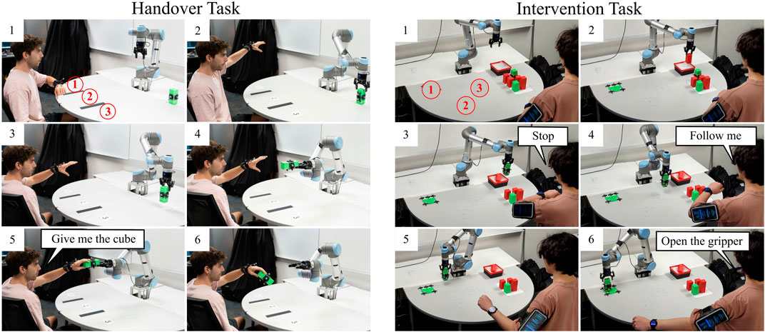
Figure 9. Handover Task: Human subjects used WearMoCap to perform handovers with a UR5. A voice command completed the handover and the robot let go of the cube. Intervention Task: The UR5 sorted the green and red cubes into the bin. Human subjects use WearMoCap to interrupt the robot and to place the green cube at a target location.
Figure 9 summarizes the steps for each handover task. From the initial setup (Step 1), the subject raised their arm in one of the three locations at random (Step 2). Then, the robot picked up the green cube (Step 3). Given the known chair position and subject’s sitting height, we tracked the hand position of the subject using WearMoCap. The robot moved the cube toward the tracked hand position (Step 4). The subject then issued a voice command (Step 5) after which the robot released the cube (Step 6). Depending upon the accuracy of hand tracking, the subject had to move their hand by a certain “handover distance” to grab the cube.
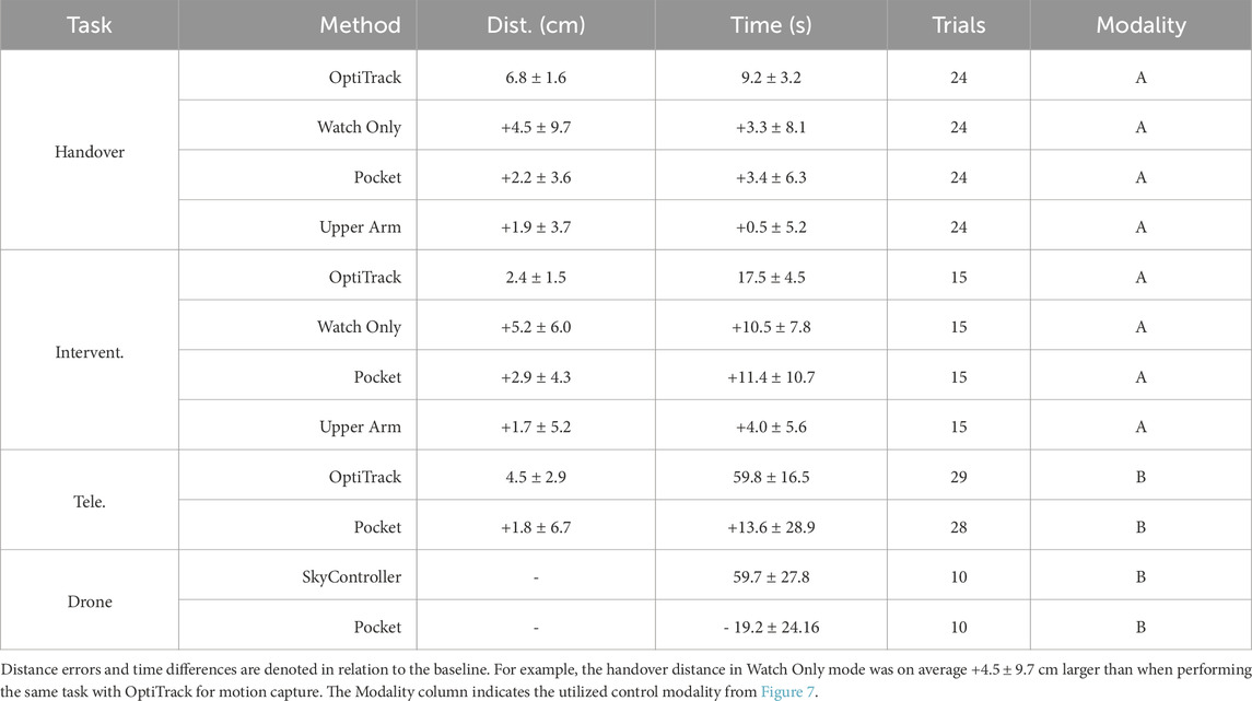
Four human subjects performed 24 tasks each, comprising six handovers with Watch Only, Upper Arm, Pocket modes and with OptiTrack. We randomized the order of tracking modes to eliminate potential biases or learning effects. We computed the handover distance, which is the difference between the hand position and the cube at the time the participant triggered the voice command (Step 5). To compute the handover distance, we located the center of the user’s wrist and the center of the cube using Optitrack markers on both. Then we took the euclidean difference between the two. We also computed the handover time, which is the time that it takes for the robot to move toward the hand and complete the handover task (from Step 2 to Step 5).
3.4.2 Intervention
In the Intervention Task, the human subject interrupts the robot during its routine when it makes a mistake, and performs corrective action. For this task, a UR5 robot was supposed to autonomously pick up a colored cube (green or red) and drop it at target locations of the same color. However, the robot was not trained to correctly place green cubes. As depicted in Step 1 on the right of Figure 9, the human subject stood in front of the robot and there were three possible target locations for the green cube. Whenever the robot picked up a green cube, the subject stopped the robot with a voice command and made it place the cube at the correct location.
Figure 9 summarizes the steps. The subject watched the robot (Step 2) and stopped it with a voice command from dropping a green cube at the red location (Step 3). Then, the subject instructed the robot to mirror their arm motion, i.e., move the robot end-effector in the same way as the subject’s wrist movement (Step 4). The WearMoCap algorithm, in conjunction with control Modality A (Figure 7), tracked the hand position and converted it into end-effector coordinates to control the robot (Step 5). The subject then issued another voice command (“Open the gripper”) to complete placing the cube at the correct location (Step 6).
Five subjects performed this task for each of the three green target locations and with each WearMoCap mode at random. The performance was evaluated with respect to the placement distance, which is the distance between the position of the placed green cube and the center of the target location. This was measured using OptiTrack. We also computed the task completion time, which is the time that elapsed between issuing the “Follow me” command and the “Open the gripper” command.
3.4.3 Teleoperation
As depicted on the left in Figure 10, subjects controlled a UR5 to pick and place cubes from a remote location through a live camera feed on their smartphone. This was done as follows: the subject initiated the task with a “Follow me” voice command, which started the hand tracking. The subject maneuvered the robot end-effector toward the cube to be picked up. The subject then issued a “Close” voice command to grab the cube. Then, the subject maneuvered the robot end-effector to the target location and dropped the cube with “Open” voice command. We employed the Pocket mode of WearMoCap, in conjunction with control Modality B (Figure 7), to estimate the end-effector position for robot control. This combination allowed the subject to control the robot through changes in their body orientation, i.e., the robot turned left (right) whenever the subject turned left (right).

Figure 10. Teleoperation Task: Human subjects used WearMoCap to pick and place a cube. They were entirely removed from the robot and only watched the end-effector through a camera feed on the phone. Drone Piloting Task: Human subjects piloted a drone to three target locations in random order. Each location was marked with an AprilTag. If a tag was recognized through the drone camera feed the target was reached.
This task was performed by five subjects for six different configurations of pick-up and target locations of the cube. For one instance using OptiTrack and two instances using WearMoCap, the task execution failed because the subject knocked over the cube. For all successful completions of the tasks, we computed the placement accuracy, which is the distance between the placed cube and the target location, as measured by OptiTrack. We also computed the task completion time, which is the time elapsed between issuing the “Follow me” and “Open” commands.
3.4.4 Drone piloting
In this task, subjects used motion capture to fly a commercial Parrot Bebop 2 drone to three target locations. Drone control via traditional remotes is hard to master while control through body motions can be more intuitive for inexperienced pilots Macchini et al. (2020). As shown on the right in Figure 10, with the subject at the center of a field, the three target locations were at distances of 4 m, 5 m, and 6 m in three directions. The targets were colored cardboard sheets with AprilTags (Wang and Olson, 2016). Subjects were instructed to fly the drone above these targets in a randomized order. A target was considered to be reached when its corresponding AprilTag ID was recognized through the downward-facing drone camera. The subjects controlled the drone with WearMoCap in Pocket mode, utilizing control Modality B. The drone used GPS and internal IMUs to follow the control commands in a stable trajectory.
Ten human subjects performed the task two times each: first, with WearMoCap and then with the original remote called SkyController. The performance was measured using drone piloting time which is the time it took for the drone from reaching the first target until reaching the third target.
3.4.5 Results summary
We summarize the objective task metrics in Table 5. For each task, we compared the performance of WearMoCap against the baseline control methods.
The Handover and Intervention tasks investigate all WearMoCap pose estimation modes Watch Only, Upper Arm, and Pocket when using control Modality A and compare to OptiTrack as the baseline method. Expectedly, the Watch Only mode is more error-prone than its counterparts, evidenced by its higher handover distance (+4.5 cm) and intervention placement distance (+5.2 cm). The Upper Arm mode is the most accurate with an increase below +2 cm in both tasks. These results are consistent with the evaluation on test data in Section 3.2. It is also noteworthy that the Pocket mode too outperformed Watch Only mode in our distance metric. This is because it offers an additional degree of freedom to fine-tune positioning. However, due to this additional degree of freedom, the Pocket mode also incurred longer task completion times, because subjects had to balance changes in arm motion with changes in body orientation.
The Teleoperation and Drone tasks applied control Modality B, which relies on body orientation estimates in Pocket mode. Pocket mode with Modality B was highly accurate in terms of distance metric, with an increase of only
4 Discussion
Reflecting on our presented results, this section discusses WearMoCap in detail: Section 4.1 contrasts all three WearMoCap modalities with their benefits and limitations. Section 4.2 discusses the broader significance of our framework, its limitations, and future work. Section 4.3 concludes this paper.
4.1 Modality trade-offs
Given the observed differences in model accuracy on test data, and varying real-robot task performance for each WearMoCap mode, we discuss the following trade-offs for their application.
4.1.1 Watch only
Using only a smartwatch is the most convenient in terms of availability and setup, but the real-robot task results demonstrate a considerable increase in placement deviations and completion times in contrast to other modes. The applicability of the Watch Only mode depends on the task. If the application requires high-fidelity teleoperation control to perform pick-and-place tasks, the prediction deviations of about 10 cm are too large to be practical. Even though users were able to complete the Intervention task in Watch Only mode, the teleoperation required patience and users were not in full control. On the contrary, in a handover task, the human can compensate for the final centimeters by reaching. In such lower-fidelity applications, being able to replace an optical motion capture system with a single smartwatch is promising for future work.
4.1.2 Upper arm
While an upper-arm fitness strap is widely used and available, it adds an extra step compared to the other two modes. Nevertheless, the increase in accuracy of arm pose tracking with two IMUs has previously been assessed in Yang et al. (2016); Joukov et al. (2017), and is confirmed by our results. Out of all WearMoCap modes, the Upper Arm mode is the most accurate on the test data and incurs the smallest deviations in our real-robot task completion times and placement accuracy compared to baselines. The relatively small placement deviations of below 2 cm suggest that this mode can be a viable alternative to robot control through motion capture from OptiTrack or Virtual Reality hardware when ease-of-setup is a concern and ubiquity matters.
4.1.3 Pocket
The Pocket mode allows for the most seamless experience because users simply put the phone in their pocket and are free to turn their body. This is in contrast to the Watch Only mode, where users have to maintain a constant forward-facing direction. Our Handover and Intervention real-robot tasks indicate that the additional tracking of body orientation enables users to exert more precise control. However, this mode is less precise than the arm pose estimates in the Upper Arm mode. The Pocket mode, therefore, balances the precision and convenience of the other two modes.
4.2 Significance and limitations
WearMoCap enables motion capture from smartwatches and smartphones. Apart from the atmospheric pressure sensor and microphone data, collected measurements are identical to those provided by other IMU devices designed for motion capture purposes, e.g., Movella’s XSens Suite (Roetenberg et al., 2009). The significant difference between WearMoCap and established IMU solutions like XSens lies in the ubiquity and familiarity of smart devices for the average user. Smartphones and smartwatches are more widespread than customized IMU units, and a large population is familiar with starting and using apps on Android OS. While our motion capture methodology would perform equally well with customized IMUs (Prayudi and Kim, 2012; Beange et al., 2018; Li et al., 2021), it is the ubiquity of smart devices that makes WearMoCap attractive for future research into low-barrier robot control interfaces.
A limitation of WearMoCap is that, because of their reliance on IMUs, the global orientation estimates of smartwatches and smartphones can be subject to sensor drift. While the virtual orientation sensors of Android or Wear OS are robust to short-lived disturbances, e.g., moving a magnet past the device, slower long-term shifts can cause considerable offsets. The Android OS estimates device orientations through sensor fusion from accelerometer, magnetometer, and gyroscope using an Extended Kalman filter. Gyroscope drift is compensated by the gravity estimate from the accelerometer and the magnetic North from the magnetometer. As a result, the orientation is mostly subject to drift around the yaw axis due to shifts in the measured magnetic North. Our training and test data includes recording sessions of up to 10 min duration. Further, during the real-robot tasks, pose estimations typically stayed robust for 15 min or longer, but we had to ask subjects to recalibrate in about 10% or the instances. To mitigate sensor drift during longer sessions, a promising direction for future work involves utilizing our employed stochastic forward passes, which result in widening solution distributions when unrealistic changes or unergonomic angles occur (also depicted in Figure 5). This way of recognizing unergonomic or impossible angles from wide distributions can help mitigating sensor drift by automatically triggering recalibration.
Another source of drift is the sensor-to-segment misalignment, i.e., if the watch is loosely worn and slips post-calibration, we expect the tracking accuracy to be affected. In our experiments, we fitted the subjects with tightly strapped watches and phones to minimize this issue. However, in the future, we can look at better understanding the impact of sensor-to-segment misalignment and adopt techniques to correct it.
A further potential limitation common to phone-based apps is that major Operating System (OS) update, e.g., Android 12 to 13, could break our application if not updated properly to handle the OS change. However, some of our older tested devices, e.g., the OnePlus N100, do not receive long-term support anymore and will not undergo major updates in the future. It is unlikely WearMoCap will break on such older devices. Android OS updates for newer devices are rolled out slowly. To handle these updates in the long run, we have enabled the Issue Tracking function in the Github repository.
Another limitation is that our method assumes default arm lengths. While this is representative of the population that we tested with, unusually long or short arm lengths might adversely affect the tracking performance. Future work will investigate the effects of large variations in anthropometry. We publish WearMoCap as open source with this work to facilitate such future investigations. Lastly, we expect that we can improve the tracking performance by adding more subjects with varied motions and differing limb lengths.
4.3 Conclusion
This work presented WearMoCap, an extensively documented open-source library for ubiquitous motion capture and robot control from a smartwatch and smartphone. It features three motion capture modes: Watch Only requires the least setup; Upper Arm is the most precise; and Pocket is the most flexible. We benchmarked these modes on large-scale datasets collected from experiments with multiple human subjects and devices. To evaluate their practical use, we demonstrated and discussed their application in four real-robot tasks. Results show that, when chosen for the appropriate task, WearMoCap serves as an ubiquitous and viable alternative to the costly state-of-the-art motion capture systems. Future work involves evaluating the applicability of WearMoCap in more scenarios and implementing strategies for mitigating sensor drift. To this end, the WearMoCap library is published as open source together with step-by-step instructions and all training and test data.
Data availability statement
The raw data supporting the conclusions of this article will be made available by the authors, without undue reservation.
Ethics statement
The studies involving humans were approved by The Institutional Review Board of Arizona State University. The studies were conducted in accordance with the local legislation and institutional requirements. The participants provided their written informed consent to participate in this study. Written informed consent was obtained from the individual(s) for the publication of any potentially identifiable images or data included in this article.
Author contributions
FCW: Writing–original draft, Conzeptualization, Methodology, Project administration. NK: Conceptualization, Writing–review and editing. OA: Writing–review and editing. HB: Conceptualization, Supervision, Writing–review and editing.
Funding
The author(s) declare that no financial support was received for the research, authorship, and/or publication of this article.
Conflict of interest
NK and OA were employed by the Corporate Functions-R&D, Procter and Gamble.
The remaining authors declare that the research was conducted in the absence of any commercial or financial relationships that could be construed as a potential conflict of interest.
Publisher’s note
All claims expressed in this article are solely those of the authors and do not necessarily represent those of their affiliated organizations, or those of the publisher, the editors and the reviewers. Any product that may be evaluated in this article, or claim that may be made by its manufacturer, is not guaranteed or endorsed by the publisher.
Supplementary material
The Supplementary Material for this article can be found online at: https://www.frontiersin.org/articles/10.3389/frobt.2024.1478016/full#supplementary-material
Footnotes
1https://cloud.google.com/speech-to-text
References
Beange, K. H., Chan, A. D., and Graham, R. B. (2018). “Evaluation of wearable imu performance for orientation estimation and motion tracking,” in 2018 IEEE international symposium on medical measurements and applications (MeMeA) (IEEE), 1–6.
Darvish, K., Penco, L., Ramos, J., Cisneros, R., Pratt, J., Yoshida, E., et al. (2023). Teleoperation of humanoid robots: a survey. IEEE Trans. Robotics 39, 1706–1727. doi:10.1109/TRO.2023.3236952
Desmarais, Y., Mottet, D., Slangen, P., and Montesinos, P. (2021). A review of 3d human pose estimation algorithms for markerless motion capture. Comput. Vis. Image Underst. 212, 103275. doi:10.1016/j.cviu.2021.103275
DeVrio, N., Mollyn, V., and Harrison, C. (2023). “Smartposer: arm pose estimation with a smartphone and smartwatch using uwb and imu data,” in Proceedings of the 36th annual ACM symposium on user interface software and technology (San Francisco, CA: UIST ’23). doi:10.1145/3586183.3606821
Fu, Z., Zhao, Q., Wu, Q., Wetzstein, G., and Finn, C.(2024). Humanplus: humanoid shadowing and imitation from humans. Available at: https://arxiv.org/abs/2406.10454(Acessed July 26, 2024).
Gal, Y., and Ghahramani, Z. (2016). “Dropout as a bayesian approximation: representing model uncertainty in deep learning,” in Proceedings of the 33rd International Conference on International Conference on Machine Learning - Volume 48 (New York, NY: JMLR.org, ICML), 16, 1050–1059.
Hauser, K., Watson, E. N., Bae, J., Bankston, J., Behnke, S., Borgia, B., et al. (2024). Analysis and perspectives on the ana avatar xprize competition. Int. J. Soc. Robotics. doi:10.1007/s12369-023-01095-w
Hindle, B. R., Keogh, J. W., and Lorimer, A. V. (2021). Inertial-based human motion capture: a technical summary of current processing methodologies for spatiotemporal and kinematic measures. Appl. Bionics Biomechanics 2021, 6628320. doi:10.1155/2021/6628320
Huang, Y., Kaufmann, M., Aksan, E., Black, M. J., Hilliges, O., and Pons-Moll, G. (2018). Deep inertial poser: learning to reconstruct human pose from sparse inertial measurements in real time. ACM Trans. Graph. (TOG) 37, 1–15. doi:10.1145/3272127.3275108
Joukov, V., Ćesić, J., Westermann, K., Marković, I., Kulić, D., and Petrović, I. (2017). “Human motion estimation on lie groups using imu measurements,” in 2017 IEEE/RSJ international conference on intelligent robots and systems (IROS) (IEEE), 1965–1972.
Lee, B.-G., Lee, B.-L., and Chung, W.-Y. (2015). “Smartwatch-based driver alertness monitoring with wearable motion and physiological sensor,” in 2015 37th annual international conference of the IEEE engineering in medicine and biology society (EMBC) (IEEE), 6126–6129.
Lee, J., and Joo, H. (2024). “Mocap everyone everywhere: lightweight motion capture with smartwatches and a head-mounted camera,” in Proceedings of the IEEE/CVF conference on computer vision and pattern recognition, 1091–1100.
Li, J., Liu, X., Wang, Z., Zhao, H., Zhang, T., Qiu, S., et al. (2021). Real-time human motion capture based on wearable inertial sensor networks. IEEE Internet Things J. 9, 8953–8966. doi:10.1109/jiot.2021.3119328
Liu, M., Yang, S., Chomsin, W., and Du, W. (2023). “Real-time tracking of smartwatch orientation and location by multitask learning,” in Proceedings of the 20th ACM Conference on Embedded Networked Sensor Systems, New York, NY, United States (Boston, MA: Association for Computing Machinery, SenSys), 120–133. doi:10.1145/3560905.3568548
Macchini, M., Havy, T., Weber, A., Schiano, F., and Floreano, D. (2020). “Hand-worn haptic interface for drone teleoperation,” in 2020 IEEE international conference on robotics and automation (ICRA), 10212–10218. doi:10.1109/ICRA40945.2020.9196664
Malleson, C., Gilbert, A., Trumble, M., Collomosse, J., Hilton, A., and Volino, M. (2017). “Real-time full-body motion capture from video and imus,” in 2017 international conference on 3D vision (3DV) (IEEE), 449–457.
Mollyn, V., Arakawa, R., Goel, M., Harrison, C., and Ahuja, K. (2023). “Imuposer: full-body pose estimation using imus in phones, watches, and earbuds,” in Proceedings of the 2023 CHI Conference on Human Factors in Computing Systems (Association for Computing Machinery), 1–12. doi:10.1145/3544548.3581392
Nagymáté, G., and Kiss, M. (2018). Application of optitrack motion capture systems in human movement analysis: a systematic literature review. Recent Innovations Mechatronics 5, 1–9. doi:10.17667/riim.2018.1/13
Noh, D., Yoon, H., and Lee, D. (2024). A decade of progress in human motion recognition: a comprehensive survey from 2010 to 2020. IEEE Access 12, 5684–5707. doi:10.1109/access.2024.3350338ACCESS.2024.3350338
Prayudi, I., and Kim, D. (2012). “Design and implementation of imu-based human arm motion capture system,” in 2012 IEEE International conference on mechatronics and automation (IEEE), 670–675.
Raghavendra, P., Sachin, M., Srinivas, P., and Talasila, V. (2017). “Design and development of a real-time, low-cost imu based human motion capture system,” in Computing and Network Sustainability: Proceedings of IRSCNS 2016 (Springer), 155–165.
Robinson, N., Tidd, B., Campbell, D., Kulić, D., and Corke, P. (2023). Robotic vision for human-robot interaction and collaboration: a survey and systematic review. J. Hum.-Robot Interact. 12, 1–66. doi:10.1145/3570731
Roetenberg, D., Luinge, H., and Slycke, P. (2009). Xsens mvn: full 6dof human motion tracking using miniature inertial sensors. Xsens Motion Technol. BV, Tech. Rep. 1, 1–7.
Shin, S., Li, Z., and Halilaj, E. (2023). Markerless motion tracking with noisy video and imu data. IEEE Trans. Biomed. Eng. 70, 3082–3092. doi:10.1109/tbme.2023.3275775
Topley, M., and Richards, J. G. (2020). A comparison of currently available optoelectronic motion capture systems. J. Biomechanics 106, 109820. doi:10.1016/j.jbiomech.2020.1098202020.109820
Villani, V., Capelli, B., Secchi, C., Fantuzzi, C., and Sabattini, L. (2020a). Humans interacting with multi-robot systems: a natural affect-based approach. Aut. Robots 44, 601–616. doi:10.1007/s10514-019-09889-6
Villani, V., Righi, M., Sabattini, L., and Secchi, C. (2020b). Wearable devices for the assessment of cognitive effort for human–robot interaction. IEEE Sensors J. 20, 13047–13056. doi:10.1109/JSEN.2020.3001635
Walker, M., Phung, T., Chakraborti, T., Williams, T., and Szafir, D. (2023). Virtual, augmented, and mixed reality for human-robot interaction: a survey and virtual design element taxonomy. J. Hum.-Robot Interact. 12, 1–39. doi:10.1145/3597623
Wang, J., and Olson, E. (2016). “AprilTag 2: efficient and robust fiducial detection,” in Proceedings of the IEEE/RSJ international conference on intelligent robots and systems (IROS), 4193–4198.
Wei, W., Kurita, K., Kuang, J., and Gao, A. (2021). “Real-time limb motion tracking with a single imu sensor for physical therapy exercises,” in 2021 43rd annual international conference of the IEEE engineering in medicine and biology society (EMBC) (IEEE), 7152–7157.
Weigend, F. C., Liu, X., and Amor, H. B. (2023a). Probabilistic differentiable filters enable ubiquitous robot control with smartwatches. Available at: https://arxiv.org/abs/2309.06606 (Acessed July 26, 2024).
Weigend, F. C., Liu, X., Sonawani, S., Kumar, N., Vasudevan, V., and Ben Amor, H. (2024). “iRoCo: intuitive robot control from anywhere using a smartwatch,” in 2024 IEEE international conference on robotics and automation (ICRA), 17800–17806. doi:10.1109/ICRA57147.2024.10610805
Weigend, F. C., Sonawani, S., Drolet, M., and Amor, H. B. (2023b). Anytime, anywhere: human arm pose from smartwatch data for ubiquitous robot control and teleoperation. In IEEE/RSJ International Conference on Intelligent Robots and Systems IROS. 3811–3818. doi:10.1109/IROS55552.2023.10341624
Keywords: motion capture, human-robot interaction, teleoperation, smartwatch, wearables, drone control, IMU motion capture
Citation: Weigend FC, Kumar N, Aran O and Ben Amor H (2025) WearMoCap: multimodal pose tracking for ubiquitous robot control using a smartwatch. Front. Robot. AI 11:1478016. doi: 10.3389/frobt.2024.1478016
Received: 09 August 2024; Accepted: 28 November 2024;
Published: 03 January 2025.
Edited by:
Anany Dwivedi, University of Waikato, New ZealandCopyright © 2025 Weigend, Kumar, Aran and Ben Amor. This is an open-access article distributed under the terms of the Creative Commons Attribution License (CC BY). The use, distribution or reproduction in other forums is permitted, provided the original author(s) and the copyright owner(s) are credited and that the original publication in this journal is cited, in accordance with accepted academic practice. No use, distribution or reproduction is permitted which does not comply with these terms.
*Correspondence: Fabian C. Weigend, ZndlaWdlbmRAYXN1LmVkdQ==
 Fabian C. Weigend
 Neelesh Kumar
 Oya Aran2
 Heni Ben Amor