- School of Intelligent Control, Changzhou Vocational Institute of Industry Technology, Changzhou, China
Introduction: This paper aims at the control problem of nonlinear systems with uncertainty in general, and avoids the deviation of sliding mode controller from the preset constraint region during the convergence process.
Methods: A sliding mode control method based on fuzzy adaptive technique was proposed by constructing obstacle Lyapunov function (BLF). Design problem of fuzzy adaptive second-order sliding mode controller considering output constraints. The Lyapunov function of the cutting barrier is designed, and the fuzzy adaptive second-order sliding mode controller is constructed by combining the Lyapunov function with the regression method. A second-order finite output sliding mode controller is designed for the inverted pendulum system. In the case of unknown external disturbance, the mathematical modeling and force analysis of the first order inverted pendulum system are carried out, and the design problem of the fuzzy adaptive second-order sliding mode controller with output restriction is studied.
Results and Discussion: The proposed fuzzy adaptive second-order sliding mode controller has a good control effect in the inverted pendulum system. The fuzzy adaptive second-order controller stabilizes the sliding mode at 0.1 in 1.25 s, while the fuzzy adaptive second-order controller makes the system state reach equilibrium in 15 s. The accuracy of fuzzy adaptive second-order sliding mode controller reaches 99.2%, which is superior to other methods in terms of balance accuracy and recall rate. The controller not only has a fast response speed, but also can effectively suppress system flutter and ensure the rapid stability of the system after constraints. This research method lays a foundation for the design of fuzzy adaptive sliding mode control algorithm.
1 Introduction
Non-linear systems are widely used in practical complex engineering, often exhibiting characteristics of multi-variable, high-order, and strong coupling. The internal uncertainty and external interference make the traditional control methods difficult to deal with, resulting in system performance degradation and even instability (John et al., 2023). In practice, the changes in system parameters and external environmental disturbances inevitably affect the control effect, so it is very important to develop a robust control method that can adapt to uncertainty. As a classical control theory verification platform, the inverted pendulum system is often used to test and verify the effectiveness of control algorithms due to its under-actuation, non-linearity, and instability (Kavikumar et al., 2022; Zare et al., 2022). SMC, also known as variable structure control, is a special form of non-linear control characterized by the discontinuity of control. The main difference of the sliding mode controller (SMC) lies in its ability to dynamically adjust the system structure, guiding the system to move along the designed sliding trajectory (Fei et al., 2022). In addition, SMC is widely used in non-linear control fields, such as robot control, path tracking, and motor control, thus becoming an important control method in the field of automatic control (Wu et al., 2022). Qiao and Wang artificially enhanced the speed control effect of the direct drive system of permanent magnet synchronous motors using a gentle conversion function instead of the conventional switching function. An SMC based on fuzzy logic was constructed. Through simulation experiments, the controller was validated in handling sudden loads and simulating actual operating loads. Compared with traditional SMC, its overshoot was smaller and its robustness was better (Qiao and Wang, 2024). Chen et al. put forward an adaptive SMC to address the challenges of conventional SMC in jitter and obtaining sliding surface derivative data. Sliding mode variables were incorporated into the super twisting algorithmic parameters while retaining the discontinuous terms within the integrated function to reduce system vibration. This research method significantly improved the side slip angle compared with traditional SMC (Chen et al., 2024). Sun et al. put forward a hybrid controlling scheme that integrated the torque allocation method and SMC technology to reduce torque fluctuations and improve the dynamic response efficiency. SMC was improved to further reduce torque fluctuations at high speeds and accelerate the response speed. It enhanced the system adaptability and verified the effectiveness of the hybrid control scheme (Sun et al., 2022).
Dong et al. put forward a stepped SMC using Lagrange law to avoid accidents caused by oscillation during container handling. Its steady state was established using Lyapunov’s theorem and Babarat’s theorem. This research method quickly reduced swing and attitude tilt, which had good fault tolerance for parameter changes (Dong et al., 2023). Zhao et al. proposed a non-singular fast SMC strategy that combined adaptive algorithms and super distortion technology to reduce the impact of disturbances on the permanent magnet linear synchronous motor servo system. A control rule for stable convergence of position signals was constructed. The control method effectively improved control accuracy and system anti-interference performance (Zhao et al., 2023). Mendoza et al. proposed a small UAV trajectory tracking control method based on the FANPID controller. The method used the adaptive characteristics of the FANPID–Lyapunov controller to estimate the rotation angle. The UAV parameters were identified by the fuzzy adaptive neuron method. The simulation results showed that the control system had advantages in self-tuning and optimization, and the error was significantly reduced compared with other PID controllers (Mendoza and Yu, 2023). Chen et al. put forward a novel tracking means for autonomous vehicles. An adaptive system adjusted the SMC gain to ensure accurate and stable tracking of vehicle speed under various conditions. After simulation verification, the proposed scheme had significant advantages compared with other existing control strategies (Chen et al., 2022). Moudoud et al. put forward a fuzzy adaptive SMC for tracking to address the uncertainty and disturbance issues faced by electric wheeled robots. This controller utilized fuzzy logic to enhance the system resistance to changes and disturbances while optimizing the convergence efficiency of vibration mitigation and positioning errors. The performance of the proposed method was validated on the MATLAB/Simulink platform (Moudoud et al., 2022). To suppress the chattering effect and maintain robustness under load variation and parameter uncertainty, Kaplan O et al. proposed a second-order sliding mode control (SOSMC) to adjust the output voltage of DC/DC step-down converters by input cpll. The results show that the controller has high tracking accuracy and strong robustness, and can effectively reduce the chattering effect of the system under any input voltage or CPL power interference (Kaplan and Bodur, 2023).
In summary, although the above methods perform well under certain conditions, they may not be stable and robust enough to cope with sudden loads and parameter changes. For example, the control strategies in Sun et al. (2022) and Dong et al. (2023) have shortcomings in fast convergence and precise control. In Zhao et al. (2023) and Mendoza and Yu (2023), adaptive algorithms and fuzzy logic were used to improve the control accuracy, but i both needed improvement under strong interference. Chen et al. (2022) and Moudoud et al. (2022) performed well on trajectory tracking, but their methods may be unable to deal with complex systems and strong coupling problems. The overtorque control strategy proposed in Kaplan and Bodur (2023) still needs to improve the tracking accuracy and robustness under the conditions of load variation and parameter uncertainty. The advantage of this method is that it combines fuzzy adaptive technology and second-order sliding mode control to improve the robustness and adaptability of the system by dynamically adjusting the control gain and introducing the barrier Lyapunov function (BLF), which focuses on suppressing chatter and dealing with output constraints.
Inverted pendulum (IP) systems are a typical class of under-actuated mechanical systems that are multi-variable, high-order, non-linear, strongly coupled, and naturally unstable. IP is a typical algorithm validation platform in the field of control, which can effectively detect the feasibility and practical value of algorithms (Chotikunnan et al., 2022). Traditional SMCs perform well in dealing with non-linear systems, but the buffeting problem still exists. Under output constraints, it is difficult for traditional control methods to ensure the stability of the system. In particular, in the fast-response scenario, the design complexity increases. It is usually necessary to combine fuzzy logic, adaptive mechanism, and other technologies. It is a typical under-actuated, highly non-linear, and unstable system commonly used to verify the effectiveness of control algorithms. In order to solve the uncertainty problem in non-linear systems, especially the inverted pendulum control problem, a second-order SMC combining fuzzy adaptive technique and the backstep method is designed. The fuzzy logic system is used to approximate the uncertainty, and the adaptive mechanism is used to adjust the control gain to ensure the stability and accuracy of the system. The effectiveness of the controller in the inverted pendulum system is verified under output constraints and unknown interference conditions.
The contribution of the research is as follows. In this paper, an innovative fuzzy adaptive second-order sliding mode control method is introduced, which combines the approximation ability of the fuzzy logic system with the robustness of second-order sliding mode control to provide new theoretical support for non-linear control systems. This method approximates the system uncertainty dynamically by fuzzy adaptive technology, effectively reduces the buffeting problem of traditional sliding mode control, and improves the smoothness and accuracy of control. To solve the problem of output limitation, the barrier Lyapunov function (BLF) technology is used to ensure that the system state converts to the equilibrium point within a limited time and does not exceed the predetermined constraints, which enhances the security and reliability. At the same time, the finite-time stability proof of the fuzzy adaptive second-order sliding mode controller is provided, which is crucial for predicting and understanding the system’s behavior.
2 Methods and materials
2.1 The second-order sliding mode control method based on fuzzy adaptive control
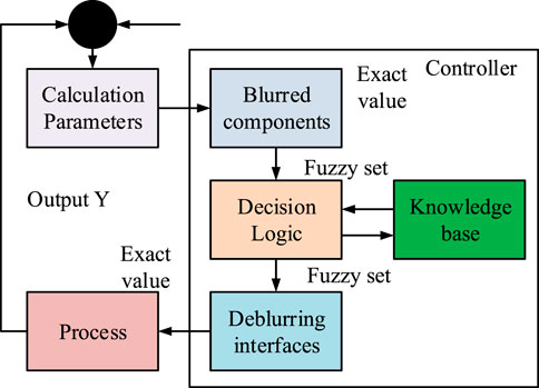
Traditional SMC has attracted much attention due to its robustness to parameter changes and external disturbances in the field of control. In practical operation, due to factors such as the component structure and the system itself, it is not possible to obtain an accurate mathematical model of the system in advance. This limits the applicability of traditional SMC in describing complex or difficult-to-quantify non-linear systems. The application of fuzzy logic can overcome this problem by estimating quasi unknown non-linear functions through language descriptions that rely on comprehensive expert experience. The study combines fuzzy control methods with robust adaptive laws to reduce the error between fuzzy approximation and actual readings. A fuzzy adaptive traditional SMC is constructed by approximating the unknown function of a non-linear system through a fuzzy logic system (FLS) and combining it with the traditional sliding mode. Figure 1 shows the proposed FLS.
In Figure 1, the fuzzy logic controller design mainly includes the following content: first, the input and output of the fuzzy controller are determined. Then, the control rules of the fuzzy controller are summarized. The methods for fuzzification and anti-fuzzification are determined. Second, the domain is chosen, and relevant parameters are determined. The initial design can be simulated. If the control performance does not meet the requirements, the membership function needs to be redefined. Sometimes, the input/output quantities need to be redefined. The knowledge base based on fuzzy rules is composed of IF-THEN rules (Gauder et al., 2023). The multiple input single output (MISO) rule is used to formulate control laws (Soukkou et al., 2023). Based on the extension of implication in multi-valued logic, the implication rule using the t-norm operator is defined in Equation 1.
In Equation 1,
Fuzzy reasoning is a mapping from a fuzzy set
After deriving Equation 3, Equation 4 can be obtained.
In Equation 4,
In most practical situations, functions
In Equation 7,
In Equation 8,
Equation 9 is substituted into the derivative of
The non-linear system
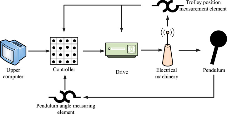
The fuzzy logic system solves the uncertainty control problem of non-linear systems. Due to the estimation of system uncertainty, the controller gain selected does not need to be too large, thereby weakening the chattering caused by the traditional sliding mode. Based on the robust adaptive law, the error between actual uncertainty and fuzzy approximation is reduced to improve the system control accuracy and performance. To cope with the external interference caused by the magnetic field and improve the robustness of the inverted pendulum system, the research method uses fuzzy logic rules to map the non-linear dynamics of the system to appropriate control parameters and then flexibly adjust them according to the current state changes. The control gain in real time is adjusted according to the different operating states of the system to improve the immunity. When the system state approaches the constrained edge, the controller increases the control input to prevent the state from deviating too much and avoid entering the unstable region. The process is completed by fuzzy logic reasoning, that is, the optimal control strategy is selected automatically according to the error and its change rate. The gain parameters are adjusted adaptively near the sliding mode surface to improve the control precision and system response speed. The optimized fuzzy adaptive SMC can realize precise control in a complex external environment and effectively resist non-linear factors such as magnetic field interference.
2.2 Fuzzy adaptive second-order sliding mode control means for the inverted pendulum system
Although the fuzzy adaptive first-order SMC strategy has some effectiveness in reducing oscillations, it still has shortcomings in eliminating vibrations compared with the second-order sliding mode. For uncertainties in non-linear systems, the traditional second-order sliding mode may no longer be applicable when there are safety and actuator structure limitations in the system. Output limitation is a challenge, which means that the system output must remain within a specific range. Otherwise, it may cause damage or performance degradation. To address these issues, research is being conducted to meet the requirement of system output limitation by referring to BLF. Then, adaptive fuzzy technology is used to dynamically approximate the uncertainty function. Finally, a new fuzzy adaptive second-order SMC is designed using adaptive control and power integral techniques. Fuzzy control has the powerful ability to approximate unknown terms in non-linear systems. The basic components of FLS include fuzzification, fuzzy reasoning, and de-fuzzification (Guo and Zhao, 2023). Equation 12 is the single-instance fuzzification mapping used.
In Equation 12,
In Equation 13,
In Equation 14,
In Equation 15,
In Equation 17,
In Equation 18,
Without considering air resistance, friction between components, and friction between the car and the ground, the linear first-level IP system can be simplified, as shown in Figure 3A. Figure 3B shows the force analysis of the car and the pendulum.
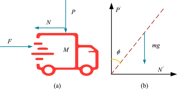
Figure 3. Force analysis of the small car and pendulum. (A) Force analysis diagram of the small car. (B) Analysis diagram of pendulum force.
In Figure 3, F represents the force applied to the car.
Equation 20 is the torque balance equation for the pendulum.
According to Lyapunov theory, the closed-loop dynamics of IP systems are finite-time stable. Equation 21 represents the fuzzy adaptive second-order mode controller u3 and the second-order SMC u4 without considering constraints.
In addition, two second-order SMCs are constructed for comparison to demonstrate the superiority of the proposed algorithm. Equation 22 represents controllers u5 and u6.
Then, the reciprocal of time along the system is taken. Equation 23 is the design of the controller.
A fuzzy adaptive second-order SMC u7 without considering output constraints is constructed in Equation 24.
The parameter vectors
The fuzzy basis function is shown in Equation 27.
The proposed fuzzy adaptive second-order SMC is applied to IP systems in research. The proposed fuzzy adaptive second-order SMC is validated through an IP system. First, the model and force analysis of the traditional linear primary IP system are presented. Then, a fuzzy adaptive second-order SMC is designed for the IP system.
To sum up, the steps of fuzzy adaptive control design are as follows: first, the mathematical model of a non-linear system is established. Because of the uncertainties in the system, such as parameter change and external disturbance, it is difficult to describe them accurately by traditional control methods. Therefore, the fuzzy logic system is used to approximate these uncertainties. The input of the fuzzy logic system is usually the error or the error change rate, and the output is the control signal. The precise values are converted to fuzzy sets by fuzzification. Then, the central average method is used for deblurring to obtain clear control values. The core is based on the IF-THEN rule base to deal with the uncertainty and non-linear problems, as well as fuzzy reasoning to achieve input–output mapping. The fuzzy controller adjusts parameters dynamically through the adaptive mechanism to improve the approximation accuracy. The design of the adaptive control law should be based on Lyapunov stability analysis to ensure the asymptotic stability of errors. In SMC, by defining the sliding surface and error, the fuzzy logic system is used to approach the uncertainty term, and fuzzy parameters are adjusted by an adaptive strategy to reduce the influence of error and uncertainty.
3 Results
3.1 Experimental analysis of the first-order sliding mode controller
The first-order SMC parameters are set as follows:
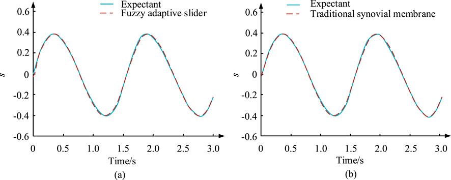
Figure 4. Response curves of the sliding variable s under the action of controllers u1 and u2. (A) Controller u1. (B) Controller u2.
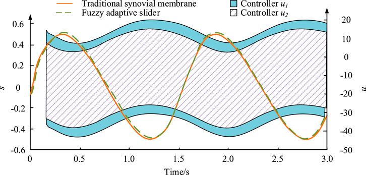
In Figure 4A, the sliding variable can accurately track the dynamic expected value, with the maximum and minimum values of 0.4 and -0.4, respectively. Therefore, the feasibility of the proposed algorithm was demonstrated. In Figure 4B, based on SMC variables, it could accurately track and adapt to dynamically changing expected targets. The motion trajectories of sliding variables under the action of two controllers were compared together. This was to verify that the proposed fuzzy adaptive first-order sliding mode algorithm can inherit the robustness of traditional sliding modes. It can, to some extent, weaken the chattering generated by the traditional sliding mode. Figure 5 presents the results.
In Figure 5, the variation range of the traditional sliding mode and fuzzy adaptive slider was very similar, with both being within −0.5–0.5. The designed fuzzy adaptive first-order SMC strategy exhibited the same robust characteristics as the traditional SMC. On the basis of achieving the same tracking effect as the common goal, the vibration generated by the newly proposed controller u2 was obviously lower than that when using the controller u1. The vibration of controller u1 was within −35–19 and that of controller u2 was within −45–19.
3.2 Experimental analysis of the performance of second-order SMC
The parameters of fuzzy adaptive second-order SMC are set as follows:
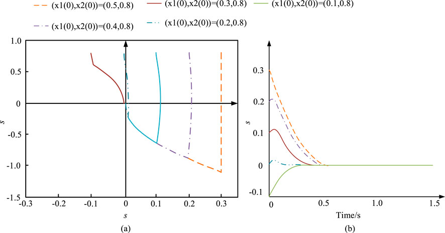
Figure 6. Phase plane trajectory and response curve of the controller during operation. (A) Phase plane trajectory of s-s ^ during the operation of the controller. (B) Response curve of s during controller operation.
Figure 6A presents a phase trajectory of s-s^ with various initial states under the action of fuzzy adaptive second-order SMC. Figure 6B shows the motion trajectory of the sliding variable s over time under the action of fuzzy adaptive second-order SMC. Figure 7A shows the motion trajectory of the system state x1 over time under the action of fuzzy adaptive second-order SMC u3. Figure 7B shows the control input signal of controller u3 in the initial state
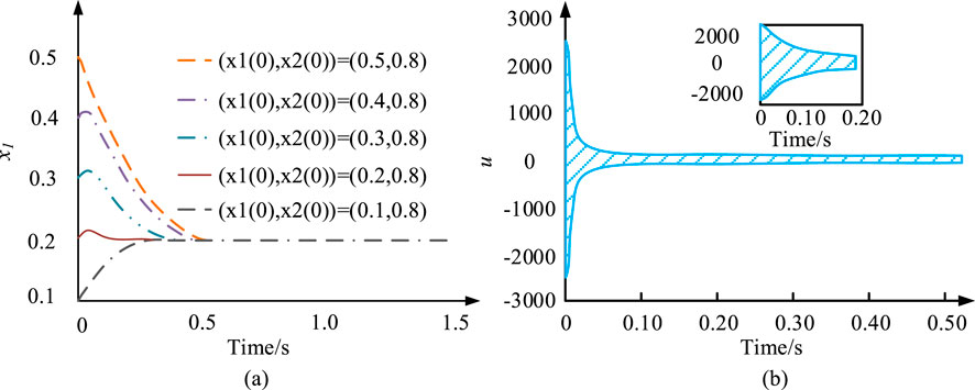
Figure 7. Time-dependent motion trajectory of the system state x1 under the action of fuzzy adaptive second-order SMC and the control input signal in the initial state. (A) Response curve of x1 during controller operation. (B) Response curve of the controller.
Figure 7A shows that the sliding state s tracked the expected value. However, the system state x1 did not cross the constraint boundary
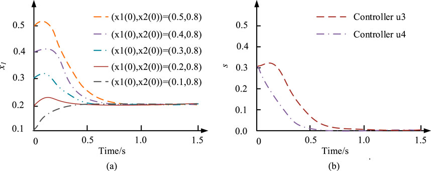
Figure 8. Simulation results under the action of controllers u3 and u4. (A) Response curve of controller u4 at x1. (B) Response curve of s under the action of controllers u3 and u4.
Figure 8A shows that under the initial condition
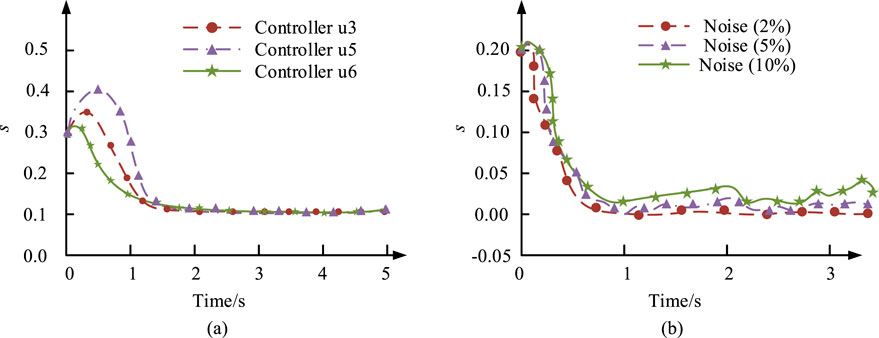
Figure 9. Simulation results of the system state under the action of controllers u3, u5, and u6. (A) Response curves of controllers u3, u5, and u6 at initial values (x1 (0), x2 (0))=(0.3, 0.8). (B) Response curve of s under the action of controller u3 with additional random noise (2%, 5%, and 10%).
Figure 9A shows the state x1 reached stability under these controllers. If the control value of the controller u3 was smaller than that of the other two controllers, its sliding variable reached a stable state within 1.25 s, with a value of 0.1. This indicates that the proposed algorithm effectively reduces chattering. Figure 9B shows the sliding variable s affected by noise interference oscillated near the equilibrium point within a finite time. As the random noise applied to the system increased, the system performance also deteriorated.
3.3 Experimental analysis of fuzzy adaptive second-order SMC
The parameter settings are as follows:
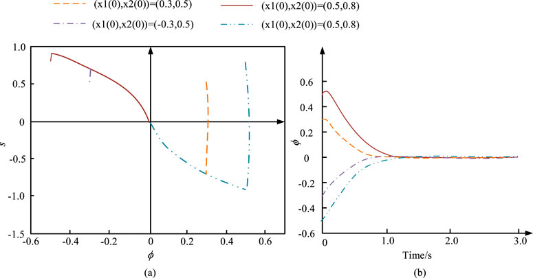
Figure 10. Simulation results of controller u8. (A) Phase plane trajectory of s-s ^ during the operation of the controller. (B) Response curve under the action of controller u8.
Figure 10A shows the
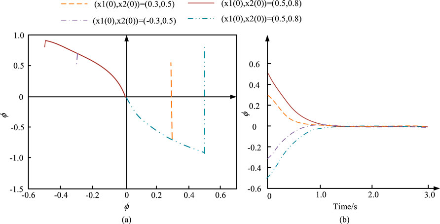
Figure 11. Simulation results of controller u8. (A) Phase plane trajectory of s-s ^ during the operation of the controller. (B) Response curve under the action of controller u7.
Figure 11A shows the sliding variable converged to the coordinate origin. When the initial value was (x1 (0), x2 (0))=(0.5, 0.8), the system state 0 did not cross the constraint boundary in the initial response. This is because when
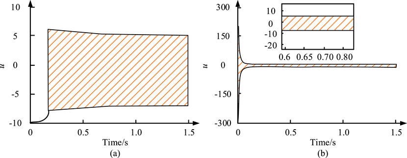
Figure 12. Response curves of u under the controllers u7 and u8. (A) Response curve of u under the action of controller u7 at initial values (x1 (0), x2 (0))=(0.5, 0.8). (B) Response curve of u under the action of controller u8 at initial values (x1 (0), x2 (0))=(0.5, 0.8).
According to Figure 12, for controller u7, at the beginning, u became large enough to constrain the state variable that was about to escape. After being constrained, u gradually decreased. As the system stabilized, u gradually stabilized within 10. To further verify the superiority of the research method, the performance of several SMCs was compared. The results are shown in Table 1.
From Table 1, the fuzzy adaptive second-order sliding mode controller (FASMC) designed in the research showed excellent performance in several indicators. In terms of accuracy, FASMC achieved 99.2%, which was significantly higher than that of other control methods in the literature. The F1 value of the research method was 0.95, indicating that FASMC was also superior to other methods in balancing accuracy and recall rate. The convergence time was only 1.25 s, which was faster than the method in the literature, indicating that the controller had a faster response in practical applications. In addition, the minimum vibration range of FASMC was only 0.1, which is far lower than that of other methods, demonstrating the advantages of the controller in terms of stability and its ability to effectively suppress flutter. Finally, the convergent state time of FASMC was 15 s, which was slightly shorter than that of other methods, further proving the efficiency of the method.
4 Discussion
This paper proposes a fuzzy adaptive second-order SMC method that significantly improves the control accuracy and system robustness, especially in suppressing chattering. Compared with traditional fuzzy sliding mode control, this method reduces the dependence on fixed gain by adjusting sliding mode gain adaptively and optimizes the control performance in a complex environment. Compared with the super-twisted sliding mode control in Chen et al. (2024), this paper achieves system stability within 1.25 s, and the speed is faster. In addition, this paper verifies its superior control effect in the inverted pendulum system, and it has a wide application prospect. Compared with the cascade sliding mode control in Dong et al. (2023), the adaptive fuzzy strategy proposed in this paper is more adaptable to system parameter changes and external disturbances. Although the stepped SMC performs well in scenarios such as anti-swing control of container gantry cranes, its adaptability and scalability are relatively insufficient. It is difficult to apply to complex systems. In this paper, the BLF is introduced to ensure the asymptotic stability under output constraints. The proposed method can converge quickly under different initial conditions, and the state is always kept within the constraint range, showing excellent adaptability and anti-interference ability. The fuzzy adaptive SMC described in Moudoud et al. (2022) has a good effect in robot trajectory tracking, but its performance degrades with strong disturbance. In this paper, fuzzy logic and adaptive mechanism are used to reduce noise interference and ensure stable operation of the system. Finally, this paper converges the sliding mode variable to 0.1 within 1.25 s, and the control input is stable within 10, which is better than that of the methods in Kaplan and Bodur (2023) and Chotikunnan et al., 2022.
5 Conclusion
A control strategy was proposed to efficiently handle non-linear systems with uncertainty. This method first designed a first-order SMC based on fuzzy logic and an adaptive mechanism and analyzed its stability. It was further extended to second-order SMC. In addition, to address output limitation issues, BLF was introduced and applied to the actual system IP. In the simulation experiment, the new algorithm not only maintained the efficient performance of the control system but also tracked the sliding variable s over time under the action of fuzzy adaptive second-order SMC. In summary, first-order SMC sliding variables accurately tracked the dynamic expected value. Its maximum and minimum values were 0.4 and −0.4, respectively. The sliding variable s converged within a finite time, thus proving the proposed algorithm’s feasibility. The variation between the traditional method and fuzzy adaptive slider was similar, with both being within −0.5–0.5. The vibration of controller u1 was within -35–19, and the vibration of controller u2 was within −45–19. This is because the fuzzy adaptive technology weakened the chattering problem in the traditional sliding mode to a certain extent. When the state x1 approached the boundary, the control input signal became very large, which verified the effectiveness of the proposed controller. The state x1 achieved its stability under these controllers. The control value of controller u3 was smaller than that of the other two controllers. The sliding variable reached a stable state within 1.25 s, with a value of 0.1. This indicated that the proposed algorithm effectively reduced chattering. When the initial value was (x1 (0), x2 (0)) =(0.5, 0.8), under the action of controller u7, the system state
Data availability statement
The original contributions presented in the study are included in the article/supplementary material; further inquiries can be directed to the corresponding author.
Author contributions
XL: conceptualization, data curation, formal analysis, investigation, methodology, project administration, resources, software, supervision, writing–original draft, and writing–review and editing.
Funding
The author(s) declare that no financial support was received for the research, authorship, and/or publication of this article.
Conflict of interest
The author declares that the research was conducted in the absence of any commercial or financial relationships that could be construed as a potential conflict of interest.
Publisher’s note
All claims expressed in this article are solely those of the authors and do not necessarily represent those of their affiliated organizations, or those of the publisher, the editors, and the reviewers. Any product that may be evaluated in this article, or claim that may be made by its manufacturer, is not guaranteed or endorsed by the publisher.
References
Chen, G., Jiang, Y., Guo, K., and Wang, L. (2022). Speed tracking control for unmanned driving robot vehicle based on fuzzy adaptive sliding mode control. IEEE Trans. Veh. Technol. 71 (12), 12617–12625. doi:10.1109/tvt.2022.3195608
Chen, Q., Xiong, Z., Hu, Y., Huang, L., Liu, Q., and You, D. (2024). AFS control system research of distributed drive electric vehicles by adaptive super-twisting sliding mode control. Trans. Inst. Meas. Control 46 (7), 1388–1396. doi:10.1177/01423312231196400
Dong, J., Sun, D., Jia, T., Sun, F., and Qin, Y. (2023). Research on anti-swing of container gantry crane as hierarchical sliding mode control. J. Fail. Analysis Prev. 23 (4), 1741–1751. doi:10.1007/s11668-023-01720-w
Fei, J., Wang, Z., and Fang, Y. (2022). Self-evolving recurrent Chebyshev fuzzy neural sliding mode control for active power filter. IEEE Trans. Industrial Inf. 19 (3), 2729–2739. doi:10.1109/tii.2022.3162855
Chotikunnan, P., Chotikunnan, R., Nirapai, A., Wongkamhang, A., Imura, P., and Sangworasil, M. (2023). Optimizing membership function tuning for fuzzy control of robotic manipulators using PID-driven data techniques. J. Robot. Control 4 (2), 128–140. doi:10.18196/jrc.v4i2.18108
Gauder, D., Goelz, J., Jung, N., and Lanza, G. (2023). Development of an adaptive quality control loop in micro-production using machine learning, analytical gear simulation, and inline focus variation metrology for zero defect manufacturing. Comput. Industry 144 (21), 103799–103804. doi:10.1016/j.compind.2022.103799
Guo, L., and Zhao, H. (2023). Online adaptive optimal control algorithm based on synchronous integral reinforcement learning with explorations. Neurocomputing 520 (2), 250–261. doi:10.1016/j.neucom.2022.11.055
Jiang, S., Song, Y., Zeng, W., Zhang, H., Cai, S., and Lu, X. (2023). New results on adaptive fixed-time control for convex-delayed neural networks. ISA Trans. 134 (21), 134–143. doi:10.1016/j.isatra.2022.08.027
John, Y. M., Sanusi, A., Yusuf, I., and Modibbo, U. M. (2023). Reliability analysis of multi-hardware–software system with failure interaction. J. Comput. Cognitive Eng. 2 (1), 38–46. doi:10.47852/bonviewjcce2202216
Kaplan, O., and Bodur, F. (2023). Second-order sliding mode controller design of buck converter with constant power load. Int. J. Control 96 (5), 1210–1226. doi:10.1080/00207179.2022.2037718
Kavikumar, R., Kwon, O. M., Lee, S. H., Lee, S. H., and Sakthivel, R. (2022). Input-output finite-time IT2 fuzzy dynamic sliding mode control for fractional-order nonlinear systems. Nonlinear Dyn. 108 (4), 3745–3760. doi:10.1007/s11071-022-07442-2
Mendoza, A. M. E. R., and Yu, W. (2023). Fuzzy adaptive control law for trajectory tracking based on a fuzzy adaptive neural PID controller of a multi-rotor unmanned aerial vehicle. Int. J. Control, Automation Syst. 21 (2), 658–670. doi:10.1007/s12555-021-0299-2
Moudoud, B., Aissaoui, H., and Diany, M. (2022). Fuzzy adaptive sliding mode controller for electrically driven wheeled mobile robot for trajectory tracking task. J. Control Decis. 9 (1), 71–79. doi:10.1080/23307706.2021.1912665
Qiao, Y., and Wang, K. (2024). Fuzzy sliding mode speed control strategy of permanent magnet motor under variable load condition. Int. J. Dyn. Control 12 (5), 1616–1625. doi:10.1007/s40435-023-01285-4
Soukkou, Y., Tadjine, M., Soukkou, A., Nibouche, M., and Nouri, H. (2023). Tuning functions based adaptive backstepping control for uncertain strict-feedback nonlinear systems using barrier Lyapunov functions with full state constraints. Eur. J. Control 70 (5), 100783–100810. doi:10.1016/j.ejcon.2023.100783
Sun, X., Xiong, Y., Yang, J., and Tian, X. (2022). Torque ripple reduction for a 12/8 switched reluctance motor based on a novel sliding mode control strategy. IEEE Trans. Transp. Electrification 9 (1), 359–369. doi:10.1109/tte.2022.3161078
Wu, T., Xue, K., and Wang, P. (2022). Leader-follower formation control of USVs using APF-based adaptive fuzzy logic nonsingular terminal sliding mode control method. J. Mech. Sci. Technol. 36 (4), 2007–2018. doi:10.1007/s12206-022-0336-y
Zare, M., Pazooki, F., and Haghighi, S. E. (2022). Quadrotor UAV position and altitude tracking using an optimized fuzzy-sliding mode control. IETE J. Res. 68 (6), 4406–4420. doi:10.1080/03772063.2020.1793694
Zhao, X., Gong, Y., Jin, H., and Xu, C. (2023). Adaptive super-twisting-based nonsingular fast terminal sliding mode control of permanent magnet linear synchronous motor. Trans. Inst. Meas. Control 45 (16), 3057–3066. doi:10.1177/01423312231162782
Keywords: fuzzy logic, adaptive, inverted pendulum, sliding mode controller, system
Citation: Leng X (2024) Second-order sliding mode optimization control of an inverted pendulum system based on fuzzy adaptive technology. Front. Mech. Eng. 10:1458852. doi: 10.3389/fmech.2024.1458852
Received: 03 July 2024; Accepted: 13 November 2024;
Published: 10 December 2024.
Edited by:
S. Hassan HosseinNia, Delft University of Technology, NetherlandsReviewed by:
Mehmet Akif Koç, Sakarya University of Applied Sciences, TürkiyeSaleh Mobayen, University of Zanjan, Iran
Copyright © 2024 Leng. This is an open-access article distributed under the terms of the Creative Commons Attribution License (CC BY). The use, distribution or reproduction in other forums is permitted, provided the original author(s) and the copyright owner(s) are credited and that the original publication in this journal is cited, in accordance with accepted academic practice. No use, distribution or reproduction is permitted which does not comply with these terms.
*Correspondence: Xuefeng Leng, bGVuZzIwMjMxMjZAMTI2LmNvbQ==
 Xuefeng Leng