 M. Leao Moreira
 R. Singh1
 B. Albakri
 V. Venugopal
 Y. Park
- 1Department of Mechanical and Industrial Engineering, University of Illinois at Chicago, Chicago, IL, United States
- 2Remote Systems Group, Oak Ridge National Laboratory, Oak Ridge, TN, United States
- 3Robotic and Remote Systems, Argonne National Laboratory, Lemont, IL, United States
In factory automation applications, the embedded control system components are often available as off-the-shelf products, while the mechanical components and environment in which they will work are still under development. Thus, the need arises to test control systems without the final assembly. This paper introduces a hardware-in-the-loop (HIL) virtual environment for control system testing, design planning, and operator training. Controller hardware and software are configured as in the actual application, whereas electro-mechanical components are virtually constructed using Unreal Engine 5 and Matlab Simulink. Motion data from the model can be used to optimize the actuator controller, make physical design assessments, and predict possible failure scenarios such as software/hardware malfunctions. The environment is used to validate an industrial gantry robot’s control systems and structural design. The testing is successful in using real-time controller inputs to generate visual display and physical assessments of the robot’s design. Similar techniques can be applied to simulate different robot configurations using Codesys and Unreal Engine 5 or similar programs.
1 Introduction
Motion control testing can be expedited through Hardware-in-the-Loop (HIL) testing. This process utilizes simulations that interface with the embedded controller without needing most of the physical machinery. HIL offers many advantages, including the ability to bypass delays in obtaining or operating physical components and saving time and resources. It also enables thorough system testing without the need to physically test in potentially unsafe environments, thus ensuring safety and reliability.
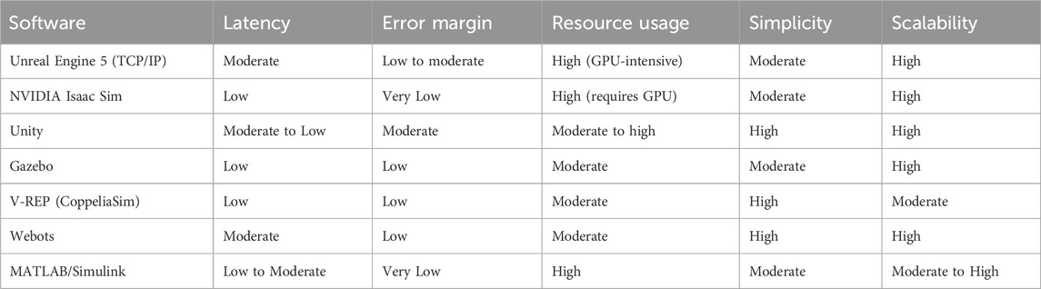
Table 1. Types of visualization software which can achieve similar functions as Unreal Engine 5 and their respective pros/cons.
In recent years, the term “digital twin” has become popular for describing simulations that resemble and interface with the same control logic as the device they represent. HIL implementation requires real-time communication between the software and hardware components and a two-way flow of information (IBM, 2024). In some cases, the simulation communicates in real-time with the existing actuators or mechanisms available, crossing into Vehicle in the loop territory. These aspects, among others, are what distinguish a digital twin from an ordinary simulation. Figure 1 shows the five major stages of embedded software testing and validation (Park et al., 2020). There are popular tools for developing digital-twins or visualizing robotic motion, some requiring a greater degree of programming understanding than others. For example, Unreal Engine 5 enables users to choose between C++ or blueprints, which function similar to ladder logic diagrams. Below is a table with tools that were considered, which that can achieve similar visualization and communication functions as Unreal Engine 5:
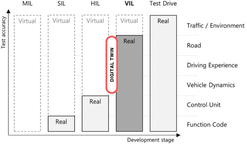
Figure 1. Embedded control software testing and validation stages. A digital twin shares characteristics between HIL and VIL functionality.
The software development and testing start with the model-in-the-loop (MIL) phase, where initial predictions about the system’s behavior are assessed. Gradually, the in-between stages, software in the loop (SIL), hardware in the loop (HIL), and vehicle in the loop (VIL), are included in the testing. SIL/HIL aims to test the system accurately and thoroughly at low cost and risk. The final stage is where testing includes the vehicle under actual operating environment conditions (Hwang et al., 2006). This comprehensive testing approach builds confidence in the control system and is crucial for safety and reliability.
This paper focuses on SIL/HIL testing, with a PLC, servo drives, and servo motors acting as the controlled hardware. To perform the testing, a digital twin environment was developed according to the specifications in the next section, “System Definition.
2 System Definition
By incorporating the digital model of the gantry in testing before deploying the actual gantry, the team is able to tailor specific scenarios for testing that validate the structural integrity and functionality of the gantry without requiring expensive facilities and the finalized mechanical device.
The system is designed to perform several vital functions:
• Real-time Virtual Representation: Display a real-time virtual representation of a described mechanical device powered by actuators and the environment it will operate in. This is performed using Epic Games’ Unreal Engine 5 (Epic Games, 2024) and MathWorks’ Simulink (MathWorks, 2024a).
• Servo Drive Control: Control servo drives that interface with both hardware and software components, facilitating precise motion control. This is achieved with Codesys Development System (Codesys Group, 2024) and Ethercat protocol.
• Integration and Communication: Link the motion of the virtual representation to the embedded controller and servo drives, ensuring seamless interaction between virtual and physical elements.
• Data Transmission: Control data packets are sent from one computer to another via Transmission Control Protocol/Internet Protocol (TCP/IP), facilitating communication between different system components.
• Remote Visualization and Control: This feature allows users to visualize and test servo motion controls remotely using wireless connectivity, enhancing accessibility and flexibility in testing scenarios.
The system architecture is composed of several hardware and software elements:
• Embedded Controller: Responsible for communication between hardware components and controller software, facilitating inter-process communication (IPC). The primary embedded controller used during testing was Advantech’s AMAX-5580 (PLC, 2024), due to its ease of interfacing with Windows computers.
• Server Computer: This computer configures servo driver behavior, hosts a TCP/IP server, and provides a virtual Human Machine Interface (HMI). It manages sending target positions and receiving real-time positions.
• Servo Driver/Motor: Receives target and real-time positions and sends real-time positions back to the embedded controller.
• Client Computer: Receives real-time positions from the embedded controller, then routes signals to Unreal Engine 5 and Simulink for visualization and analysis. The server and client computers can often be the same machine. However, it may be beneficial to utilize multiple computers due to the intensive resources the applications utilize.
3 System setup
The HIL testing configuration, shown in Figure 2, utilizes a server computer running CODESYS with a built-in Human Machine Interface (HMI) system to program the embedded controller. Servo drives interface with the EtherCAT (EtherCAT, 2024) protocol for enhanced feedback response time and precision. Commands are transmitted from the embedded controller to the servo drives and the client computer.
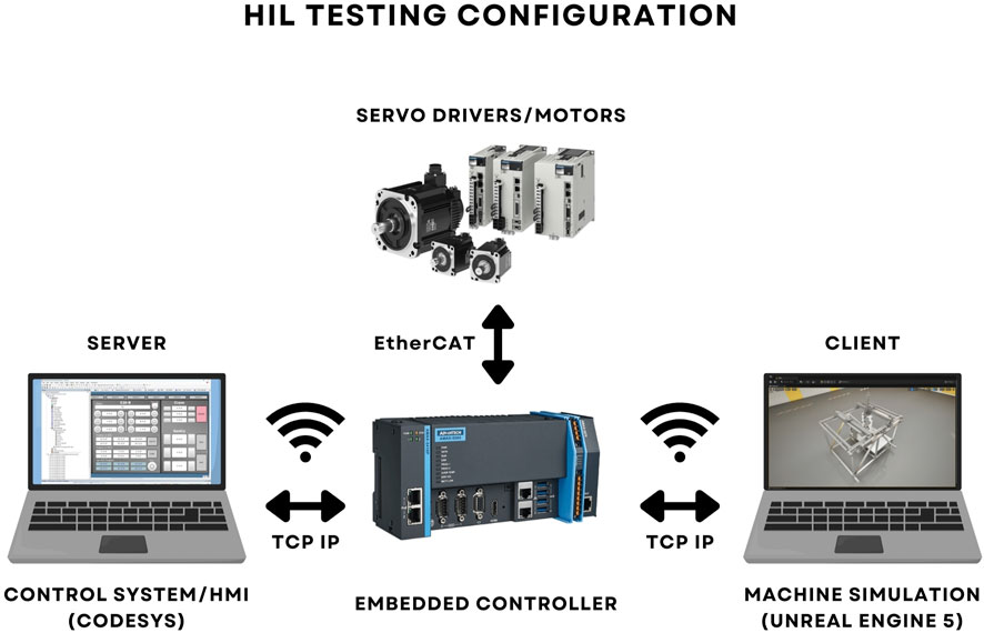
Figure 2. HIL Testing configuration with real-time visualization.
Unreal Engine receives the servo’s actual positions on the client computer and uses them to power a virtual representation of the machine. In the same client computer, a Matlab Simulink session performs dynamic calculations of the system and records the positions of the servo drives for analysis. In this manner, a combination of 3D visuals, motion data processing, and real-time display aids the designer in validating the motion controller, as well as the physical design of the machine. Sections 3.1-3.3 detail the functionality of the three programs.
3.1 Controller software
The motion control signals originate from IEC-61131-3 (IEC 61131-3, 2024) code written in Codesys on the server computer. The code establishes a TCP/IP server and configures servo drive dynamic behavior and the sequence of movements to be performed by the servos. These functions are written in a program, downloaded via Inter-Process Communication (IPC) to the embedded controller, and controlled via a user interface. A combination of jog and absolute position commands is used to achieve meaningful sequencing of the servos.
A Human-Machine Interface (HMI) was created to allow communication between the user and the system. The HMI seen in Figure 3 allows the user to enable or disable the server and servo drives, send homing and jog signals, and trigger paths from a user-programmed sequence. The desired position of the servo defined by user input is referred to as the Target Position.
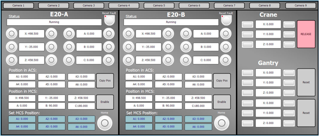
Figure 3. CODESYS Human Machine Interface (HMI) to control the gantry.
When running the motion sequence, the embedded controller signals the servo motors to reach the target position, respecting behavior and limits imposed by the user, such as maximum velocity and torque. The target position is not necessarily the actual position of the servo. In the case of a physical impedance of the servo motor or a simulated impedance by locking the actual position value, there will be a mismatch between the target and actual positions. Therefore, it becomes crucial to consider the actual position values rather than the target values when transmitting the data to the client computer.
Then, the need arises to send the actual position signals to the client’s computer. To do this, two TCP/IP server programs are written in Codesys (Codesys CAA Net Base Services Library), each operating on a separate port. One server communicates with a TCP client in Unreal Engine (SpartanTools–Code Plugins, 2024), and the other with a TCP client in Simulink (Simulink TCP/IP Plugin) for sending the same motion signals simultaneously. This retains independence between the two software, allowing for only the simulation or the data plotting tools to be used if desired. The two servers send discrete data in the form of periodic arrays, triggered every 20 milliseconds, with size and data types configured by the user.
Although the control system is currently written in Codesys, the server’s TCP/IP capability is present in relevant programming languages and similar development suites, allowing the system’s connectivity to be expanded to fit the user’s needs. Plans are in place to test the system’s functionality on alternate hardware and communication protocols.
3.2 Visualization
Unreal Engine 5 is a video game creation engine with networking capabilities that favor its integration in a TCP/IP chain. The ability to import CAD models and retain their dimensions is also taken advantage of. In this example, an industrial gantry provided by Oak Ridge National Laboratory is used to demonstrate the visualization capabilities of the system, as seen in Figure 4. The gantry has two trolley and girder assemblies that allow movement in the x and y-axes, while a hook tool and robotic mount move vertically in the z-axis.
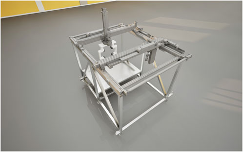
Figure 4. Industrial gantry model loaded in Unreal Engine 5 for real-time visualization of the controller signals. The model was provided by Oak Ridge National Laboratory.
Unreal Engine 5 development is free to use and has state-of-the-art graphics capabilities, which are superior to those of other robotic digital twins such as Delmia or Twinmotion. Finally, Unreal Engine 5 has an active community that develops plugins and tools that facilitate the development of digital twins, such as TCP/IP connections and Real-time plotting tools.
The gantry’s CAD assembly is loaded into Unreal Engine 5 and retains its dimensions and organization, creating meshes for each part. Actual position inputs from the embedded controller are then mapped onto the meshes to simulate the gantry’s mechanical actuation. The workflow for incorporating a new CAD model and mapping its meshes to actual position signals is shown in Figure 5.
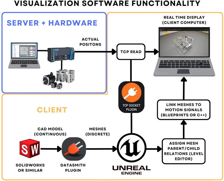
Figure 5. Visualization software functionality for linking actual position signals to a loaded CAD model in Unreal Engine 5.
Blueprints, Unreal Engine’s convenient script-building tool, was used for many functionalities, including receiving messages and rigging the gantry. The TCP/IP client is configured to read messages as soon as received, storing them to variables output to the mesh positions or angles. In this manner, the sequence of discrete position signals generates the animation of the simulated model. It is important to note that accurate representation of the motion signals requires a stable framerate and a server that can handle the frequency and size of signals sent. This is one of the reasons for considering running server and client computers as separate machines: splitting the resource load of the motion controller to one machine and visuals to another. It is notable that Unreal Engine 5 also supports scripting in C++ and Python to accomplish the same functions as blueprints.
Although the physics engine of Unreal Engine 5 is sufficient for simple interactions with the environment, intrinsic properties such as material failure and strain are less straightforward to convey. However, this is a required functionality that would offer valuable insights into the interaction of the controls with the structural integrity of the physical design. MATLAB Simulink software is used to accomplish this, as discussed in the next section.
3.3 Dynamic model
While Unreal Engine 5 focuses on interactions with the environment and visual representation of the operation, Simulink can be used in conjunction to take advantage of the many toolboxes available for validating mechanical systems. As seen in the paper, Simulink allows for plotting a variety of parameters while reflecting the physical position observed in Unreal Engine 5. Together, the tools complement each other.
Some aspects of a digital twin are challenging to represent in a visual model only. For instance, plotting and tables better visualize a structure’s surface temperature or internal stresses. This is where Simulink excels by allowing real-time recording, display, and manipulation of the embedded control signals.
To demonstrate, Simulink is employed to analyze the structural behavior of the industrial gantry’s trolley and beam interface. A simplified diagram of the gantry’s components can be seen in Figure 6. For testing, beam “A,” trolley “1,” and tool “3” are considered, with the trolley being the pressure application point. The beam is modeled as a double fixed support beam, with a point force that changes position along the x-axis (Budynas-Nisbett, 2024), (Stress Analysis Manual, 1986). First, a shear model is developed following the equation:
Where a = beam section to the left of the trolley, b = beam section to the right, x = point where the shear is analyzed, L = full length of support beam, and P = Force. Sa = L+2a and Sb = L+2b. Next, the reactions and moments of the supports are calculated as seen in Equation 3 and Equation 4, respectively, using the variables already established.
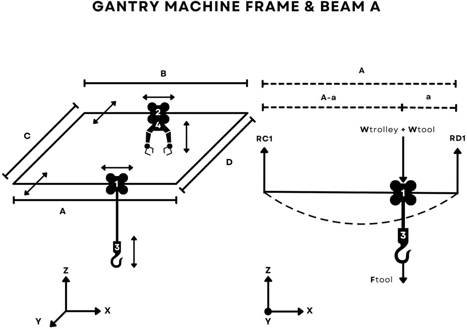
Figure 6. Layout of movements possible by each component of the gantry. The components considered for the analysis are the trolley “1” and beam “A”, with a length of 2 m. The weight of the trolley and tool are considered when calculating shear force and deflection on the beam.
Equation 4 is used to calculate the deflection at point any point x along beam “A” due to pressure F at x = a.
Where a, b, x, L, and F are the same as Equation 1, E = Modulus of Elasticity of beam material, and I = Moment of Inertia of beam (Fixed Beam Formulas, 2024), (Support reactions of a simply supported beam, 2024). Using the equations above, it becomes possible to construct a Simulink function block diagram that takes in the actual position from the embedded controller and plots the deflection and shear when the trolley is at that position. The user inputs the weight, material, and geometry of the materials affected and should be known beforehand. In the case of the beam, the elastic modulus of 1,040 steel is chosen, while the Force is calculated from the theoretical weight of the trolley and tool, as well as the vertical acceleration of the tool. The actual position signals are received by the TCP/IP Receive function and then fed into Matlab function blocks, where custom scripts perform the calculation and plotting. The function block diagram can be seen in Figure 7, while the shear and deflection functions are in Figure 8. The plots generated and comparison with the visual model are found in Section 5, Results. The equations above showcase how custom dynamics can be implemented and adapted to model different mechanical systems. The following section explains the criteria for testing the functionality of the overall system.
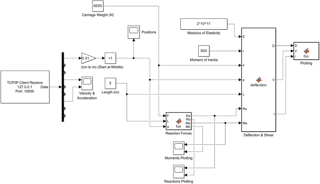
Figure 7. A Simulink diagram is used to model the deflection and shear forces on beam A based on the actual position of the trolley along the x-axis.
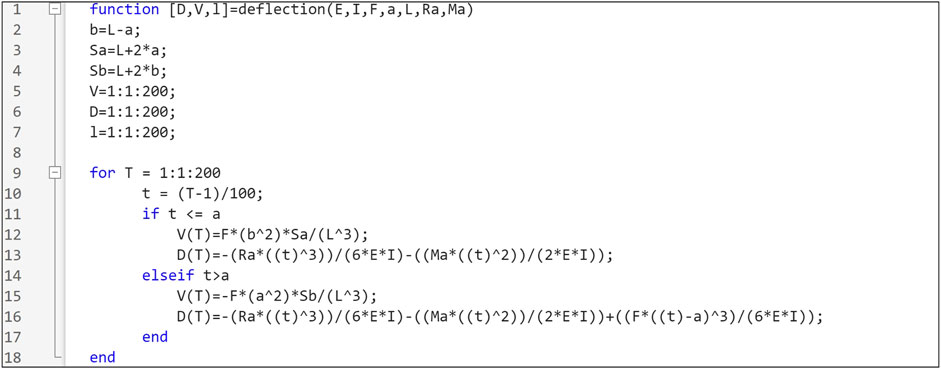
Figure 8. MATLAB function block used to model deflection and shear. The input variable “a” takes the actual position of trolley “1” along beam “A” as labeled in Figure 6. The iteration variables “T” and “t” represent the x value, allowing the user to visualize the effect on the entire beam.
4 Methods
To test the system, a sequence of commands is written to the embedded controller using Codesys and visualized in the simulation and dynamics model, and the results of the simulation and dynamic models are recorded. A relation between the servo’s actual position value and the trolley’s linear travel is established, where one servo tick = 1 cm. The trolley begins resting at the center of the beam, or x = 100 cm. Then, it travels to the length of 70 cm on the beam, using an absolute position command. Then, another command is given to the trolley, moving it to the length of 150 cm.
The velocity, acceleration, and jerk of the servo are known because it was previously chosen by the user in codesys to be ten ticks each. This means that its maximum velocity of 10 cm per second and the maximum acceleration of 10 cm per second squared should be displayed in Simulink. The recorded data is then used to generate figures that allow visualization of the sequence and comparison to the Unreal Engine 5 sequence. Plotting results against time is done with a “scope” block, while plots of x against y data are generated using the “plot” function.
Using the same formulas, the deflection and shear calculations were compared with handwritten and Excel spreadsheet solutions, as seen in Datasheet 2.1. The trolley weight is 5000N, while its elastic modulus is
5 Results
The system is validated by running the components simultaneously, observing their functionality, and verifying the data. The first step is to confirm that Simulink is accurately receiving motion signals. This is done by observing position, velocity, and acceleration signals to Simulink and confirming that they match the embedded controller value at that time. This can be seen in Figure 9, where kinematic signals for a servo drive during the sequence are shown, validating the acceleration and velocity limits. A similar process is done for Unreal Engine, confirming the mesh movements match the incoming motion signals and respect limits imposed by the control software, stopping before reaching the edge of the beam. The user can observe the trolley motion in Unreal Engine 5 and the beam’s corresponding shear and deflection plots, as seen in Supplementary Video S1. As the trolley moves, the shear force is minimized and equal on both sides when the load is centered, and moving the load away from the center progressively increases the shear force on the closer side, while decreasing it on the farther side. Utilizing the statics model described and taking into account the position limits of the trolley, the maximum shear force predicted during operation is 4100 N, which is observed when the load is closest to the edge of the beam. Other valuable data, such as the reaction forces and moments at the fixed supports, can be seen in Figure 10, achieved similarly to the velocity and acceleration plots. With the configuration for this experiment, there is no load being carried by the gantry. In other words, the predicted weight is based on the geometry and material of the trolley and hook alone. The maximum recorded deflection was
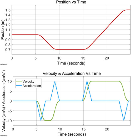
Figure 9. Position, Velocity and Acceleration versus time graphs of the trolley in the x direction.
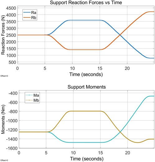
Figure 10. Support Reaction Forces and Moments at the ends of the beam “A”.
6 Conclusion
As mechanical systems become more complex and are utilized to tackle challenges in unsafe environments, hardware-in-the-loop (HIL) testing and visualization will be key technologies used to thoroughly test these systems swiftly, safely, and reliably. Currently, the main challenges involve increasing the complexity of dynamics simulation to make more meaningful physical design assessments and increasing system compatibility. These challenges are offset by the ease of use of the system and continuous support from the community, particularly for Unreal Engine 5 development. By performing validation in the virtual environment and then connecting it with the embedded control hardware, the engineer now has additional tools to ensure the functionality of their design. Comparing the maximum shear experienced during the simulation with the permissible shear for the part analyzed, the user can verify that this value did not exceed limits at any point of the trajectory where the point-mass is applied. In recent years, companies like Siemens and Dassault Systems are finding value in virtualizing their testing, which is often large-scale and requires a lot of resources. The system developed demonstrates that HIL testing is possible using free programs while offering more freedom to the user. With the expanding interest of the community, lightweight and efficient HIL testing techniques like the ones presented will continue to make their way into the consumer market, revolutionizing control systems testing for a large pool of professionals.
Data availability statement
The original contributions presented in the study are included in the article/Supplementary Material, further inquiries can be directed to the corresponding author.
Author contributions
ML: Conceptualization, Investigation, Methodology, Software, Validation, Visualization, Writing–original draft, Writing–review and editing. RS: Conceptualization, Methodology, Software, Supervision, Writing–review and editing. AG-B: Formal Analysis, Investigation, Methodology, Software, Validation, Writing–original draft, Writing–review and editing. BA: Investigation, Supervision, Writing–review and editing. VV: Conceptualization, Resources, Supervision, Validation, Visualization, Writing–review and editing. YP: Conceptualization, Resources, Supervision, Validation, Visualization, Writing–review and editing. SC: Conceptualization, Funding acquisition, Project administration, Resources, Supervision, Writing–original draft, Writing–review and editing.
Funding
The author(s) declare that financial support was received for the research, authorship, and/or publication of this article. This project was funded by the “Department of Energy Minority Serving Institute Partnership Program” fund and the “University of Illinois Chicago Department of Mechanical and Industrial Engineering” in the school year 2023–2024.
Conflict of interest
The authors declare that the research was conducted in the absence of any commercial or financial relationships that could be construed as a potential conflict of interest.
Publisher’s note
All claims expressed in this article are solely those of the authors and do not necessarily represent those of their affiliated organizations, or those of the publisher, the editors and the reviewers. Any product that may be evaluated in this article, or claim that may be made by its manufacturer, is not guaranteed or endorsed by the publisher.
Supplementary material
The Supplementary Material for this article can be found online at: https://www.frontiersin.org/articles/10.3389/fmech.2024.1451042/full#supplementary-material
References
Allowed Vertical Deflection (2024). Available at: https://www.spanco.com/blog/understanding-overhead-crane-deflection-and-criteria/ (Accessed June 11, 2024).
Codesys CAA Net Base Services Library TCP/IP example. Available at: https://content.helpme-codesys.com/en/libs/CAA%20Net%20Base%20Services/3.5.17.0/CAA-Net-Base-Services/Examples/fld-Examples.html (Accessed June 09, 2024).
Codesys Group. (2024). Codesys development system. Available at: https://www.codesys.com/products/codesys-engineering/development-system.html (Accessed June 11, 2024).
Epic Games (2024). Unreal engine 5. Available at: https://www.unrealengine.com/(Accessed June 9, 2024).
EtherCAT EtherCAT Technology Group. 2024. Available at: https://www.ethercat.org/default.htm [Accessed June 11, 2024].
Fixed Beam Formulas (2024). Available at: https://calcresource.com/statics-fixed-beam.html (Accessed June 9, 2024).
Hwang, T., Rohl, J., Park, K., Hwang, J., Lee, K. H., Lee, K., et al. (2006). “Development of HIL systems for active brake control systems,” in SICE-ICASE international joint conference.
IBM (2024). Definition of a digital twin. Available at: https://www.ibm.com/topics/what-is-a-digital-twin (Accessed June 9, 2024).
IEC 61131-3 (2024). Languages. Available at: https://en.wikipedia.org/wiki/IEC_61131-3 June 11, 2024).
Park, C., Chung, S., and Lee, H. (2020). Vehicle-in-the-loop in global coordinates for advanced driver assistance system. Appl. Sci. 10, 2645. doi:10.3390/app10082645
PLC (2024). Advantech AMAX 5580. Available at: https://www.advantech.com/en-us/products/1d0bda64-7223-4ef3-8285-feb59be81eb8/amax-5580/mod_4c16af29-eaa0-4013-980a-05ad3d6793d6 (Accessed June 11, 2024).
MathWorks (2024). MATLAB Simulink. Available at: https://www.mathworks.com/products/simulink.html (Accessed June 9, 2024).
MathWorks (2024a). Simulink TCP/IP Network for MATLAB 2024a. Available at: https://www.mathworks.com/help/instrument/send-and-receive-data-over-a-tcpip-network.html (Accessed June 9, 2024).
SpartanTools – Code Plugins (2024). TCP/IP socket plugin for unreal engine. Available at: https://www.unrealengine.com/marketplace/en-US/product/tcp-socket-plugin (Accessed June 9, 2024).
Support reactions of a simply supported beam (2024). Dr. Minas E. Lemonis. Available at: https://mechanicalc.com/reference/beam-analysis (Accessed June 9, 2024).
Keywords: robotics, digital-twin, embedded controller, CoDeSys, MATLAB, simulink, unreal engine
Citation: Leao Moreira M, Singh R, Gomez-Badillo A, Albakri B, Venugopal V, Park Y and Cetin S (2025) Hardware-in-the-loop controller testing and visualization of an industrial gantry. Front. Mech. Eng. 10:1451042. doi: 10.3389/fmech.2024.1451042
Received: 18 June 2024; Accepted: 06 December 2024;
Published: 03 February 2025.
Edited by:
Sohel Anwar, Purdue University Indianapolis, United StatesReviewed by:
Lei Liu, Liaoning University of Technology, ChinaSourav Pramanik, Purdue University, United States
Copyright © 2025 Leao Moreira, Singh, Gomez-Badillo, Albakri, Venugopal, Park and Cetin. This is an open-access article distributed under the terms of the Creative Commons Attribution License (CC BY). The use, distribution or reproduction in other forums is permitted, provided the original author(s) and the copyright owner(s) are credited and that the original publication in this journal is cited, in accordance with accepted academic practice. No use, distribution or reproduction is permitted which does not comply with these terms.
*Correspondence: S. Cetin, c2NldGluQHVpYy5lZHU=