- 1College of Engineering, Ocean University of China, Qingdao, China
- 2Qingdao GoSci Technology Group, Qingdao, China
- 3Shandong Province Key Laboratory of Ocean Engineering, Ocean University of China, Qingdao, China
- 4PLA Naval Submarine Academy, Qingdao, China
- 5Qingdao No.58 High School of Shangdong Province, Qingdao, China
The use of pile-supported breakwaters can be a cost-effective solution for wave energy dissipation when traditional rubble mound breakwaters are not suitable. For a cost-effective design of these barriers, it is essential to obtain accurate estimates of dynamic pressures and wave forces. Laboratory experiments were conducted to investigate the dynamic pressures and forces on a novel pile-supported breakwater with inclined perforated plates. The analysis focused on various wave and structural parameters, including incident wave height, wave period, plate porosity, and plate configuration. For double-layer configurations with the same porosity, dynamic pressures on the single-layer or front plate were significantly higher than on the rear plate, with rear plate forces being 20% to 60% less. The dynamic pressure on the rear plate exhibited a uniform vertical distribution. Varying plate porosity at different locations significantly impacted structural forces. Gradually decreasing porosity improved wave dissipation and reduced forces on the plates, with front and back plate forces reaching approximately 70% of those on single-layer plates. Optimal protection across various wave periods can be achieved by adjusting porosity and plate arrangement. These findings provide valuable insights for designing pile-supported breakwaters in coastal protection engineering.
1 Introduction
As marine traffic increases, constructing deep-water facilities for vessel berthing and cargo handling is crucial. Traditional rubble mound breakwaters disrupt sediment transport and may not be economically feasible in deep waters. Therefore, cost-effective, easily constructible, and environmentally friendly wave-damping structures are needed. Given that wave energy is primarily concentrated near the water surface, unconventional breakwater designs, such as floating breakwaters and pile-supported breakwaters, have been proposed (He and Huang, 2014; Liang et al., 2022). Floating breakwaters typically consist of a floating body and a mooring system, which maintains the structure at a specific draft depth in an equilibrium position. These breakwaters offer several advantages, including low cost, ease of installation and dismantling, and insensitivity to tidal fluctuations and seabed geological conditions, making them particularly suitable for deep-water applications (Ji et al., 2016). In recent years, as marine development extends into deeper waters, floating breakwaters or docks have garnered increasing attention from both academic and engineering sectors (Kar et al., 2019). However, concerns regarding the stability and performance of floating structures in challenging marine environments persist (Chen et al., 2023; Cheng et al., 2022; Dai et al., 2018; He et al., 2023). Additionally, the application of floating breakwaters in large harbors remains in its early stages. According to Karthik Ramnarayan et al. (2022), Pile-supported breakwaters, suitable for water depths over 20 meters, may provide another solution. These structures consist of a superstructure for wave attenuation and a pile foundation for support. The superstructure’s submergence degree can regulate wave attenuation, offering advantages such as suitability for soft soil, minimal environmental disturbance, and a smaller seafloor footprint.
Research has explored various superstructure designs for pile-supported breakwaters, including vertical barriers and porous structures, which attenuate wave energy effectively (Karthik Ramnarayan et al., 2020). The interaction between waves and vertical barriers has been a subject of interest for several researchers (Buccino et al., 2019; Neelamani and Vedagiri, 2002; Thanh and Dat, 2020; Zhang et al., 2022). Vertical-type pile-supported breakwaters have demonstrated the ability to achieve reduced transmission coefficients in deep-water conditions. Caissons are primarily designed to serve additional significant functions, such as mooring and facilitating loading and unloading operations. Furthermore, the construction of caissons is generally more efficient and portable compared to rubble mound breakwaters, allowing them to adapt to specialized environments, such as deep ocean floor beds or areas with abrupt changes in seabed topography (Jin et al., 2024; Özgür Kirca and Sedat KabdaŞLi, 2009; Teng et al., 2004). Additionally, the elevation on the wave-facing side can be adjusted to mitigate the effects of wave overtopping. However, vertical-type breakwaters tend to reflect waves strongly. Interest in porous breakwaters is growing due to their ability to reduce reflections and improve water exchange. Liu et al. (2023) investigated the interaction of solitary wave with perforated caisson breakwaters. The findings demonstrated that the perforated design effectively reduces the heights of both reflected and transmitted waves, with delayed reflections attributed to the presence of wave chambers, in contrast to non-perforated caissons. Liu et al. (2021) examined the wave overtopping performance of perforated caisson breakwaters under regular wave conditions. The results indicated that the wave energy carried by the overtopping current is significantly less than the energy dissipated by the breakwater. Additionally, minimizing air compression within the wave chamber effectively reduces wave overtopping, while increasing caisson porosity or the width of the wave chamber also contributes to a reduction in overtopping.
The effects of various parameters, such as the number of porous plates, wall porosity, and incident wave height, on the hydrodynamic characteristics of porous barriers have been extensively investigated by researchers (Fugazza and Natale, 1992; Isaacson et al., 1999; Mallayachari and Sundar, 1994). Various optimized structural forms have been proposed, including single or multiple vertical porous plates (Han and Wang, 2022; Vijay et al., 2020), and inclined permeable plates (Cho and Kim, 2008; Rao et al., 2009). The porous plate has been identified as a highly efficient wave dissipation component by numerous scholars. For instance, Ji and Suh (2010) demonstrated that two- and three-row slotted barriers performed better than single-slotted barrier. Alsaydalani et al. (2017) utilized eigenfunction expansion and least squares techniques to investigate the hydrodynamic performance of three rows of vertical slotted wall barriers, revealing their wave reflection and energy dissipation characteristics. Neelamani et al. (2017) illustrating a reduction in reflection coefficients from 0.9 to 0.3 by increasing the number of porous walls from one to six, thereby improving protection against long-period waves. Furthermore, Koraim et al. (2011) concluded that adjusting the opening rate of the wave-facing side of the wave wall had a more significant impact on wave dissipation performance than adjustments made to the near-shore side. Experimental studies by Vijay et al. (2019) on the interaction of regular waves with slotted wall barriers revealed that reflection decreases with an increase in the number of slotted walls, especially for long wave conditions. Alkhalidi et al. (2020) tested single and twin-slotted barriers with varying slopes and porosities under random wave conditions, demonstrating that adding a second wall was more effective in reducing the transmission coefficient compared to other wall parameters.
The successful design of perforated wave barriers necessitates a comprehensive understanding of wave scattering associated with these structures. A critical aspect of this understanding is the knowledge of dynamic pressures and forces induced by various incident wave conditions, which is essential for cost-effective structural design. This study primarily focuses on these dynamic forces acting on vertical porous walls, a key parameter in ensuring the stability of such structures. Previous research has examined the horizontal forces on porous walls. Takahashi (2002) examined the horizontal forces acting on porous walls and proposed modifications to Goda’s formula, which has since gained wide acceptance. Huang et al. (2011) conducted an extensive investigation into the hydraulic performance and wave loads of perforated coastal structures. However, there remains a notable scarcity of research concerning grooved revetments with more than two to three rows. Alkhalidi et al. (2015a) and Alkhalidi et al. (2015b) explored the dynamic pressures and wave forces on single and twin-wave barriers with varying porosities under both regular and random wave conditions. Their findings indicated that the forces on the front panel of twin-wave barriers were 20-25% higher compared to a single porous wall, while the forces on the rear or second barrier were always 20-25% lower than those on a single-wave barrier under identical test conditions. Neelamani and Al-Anjari (2021) conducted an experimental study to evaluate wave-induced pressure on slotted vertical barriers. Wave barrier configurations with six porosities and six number combinations were tested for different combinations of significant wave heights and peak periods in a random wave field in the JONSWAP spectrum. Their results demonstrated a gradual decrease in dynamic pressure from the seashore to the rear of the barrier. Vijay et al. (2022) analyze the scattering of surface gravity waves by skirt wall breakwaters, employing small-amplitude wave theory and Darcy’s law. Their study concludes that increasing the number of porous skirt walls can significantly reduce wave transmission while simultaneously increasing horizontal wave forces. Nishad et al. (2024) investigate gravity wave scattering by inverted T-type porous barriers utilizing small amplitude wave theory and an iterative Dual Boundary Element Method (DBEM). Their findings indicate that increased porosity leads to a reduction in wave forces while enhancing wave transmission. The authors recommend optimizing barrier width to decrease transmission, despite an increase in vertical forces, thereby providing valuable insights for the design of inverted T-type wave barriers.Thus, the optimal design of porous structures should consider both their protective effects against waves and the resulting force conditions.
Preliminary experiments indicate that increasing porosity considerably elevates the wave transmission coefficient. Furthermore, adding more plate layers enhances wave attenuation and decreases wave reflection. Configuring a front layer with higher porosity alongside a back layer with lower porosity markedly improves the wave attenuation capabilities of the breakwater. Under certain hydrodynamic conditions, the breakwater model can achieve wave transmission and reflection coefficients below 0.3, significantly enhancing its overall hydrodynamic performance. For the structural design of the plates of the perforated walls, it is necessary to have a comprehensive understanding of wave-induced pressures under a wide range of incident wave conditions. The influence of porosity and the number of porous walls on dynamic pressure is also a vital consideration. Ideally, a well-designed wave barrier should have a minimal number of slotted walls with maximum porosity to minimize material usage. However, existing studies have predominantly concentrated on multilayer configurations with uniform porosity, resulting in a gap in research regarding the effects of varying porosity on wave-induced dynamic pressures and forces. To address this gap, a detailed experimental study on pile-supported permeable breakwaters with inclined perforated plates was conducted.
This paper presents a series of physical model tests aimed at investigating the wave forces acting on these novel-type structures in relation to different plate porosities and configurations. The primary objective was to measure the wave-induced pressure on the plates and analyze the data to derive significant insights. The experimental tests were performed in a two-dimensional wave flume under regular wave conditions, involving six distinct structural configurations with variations in plate porosity, wave height, and wave period. The dynamic pressures and forces acting on the structure were meticulously investigated. The findings of this study provide preliminary evidence that lays the groundwork for further analyses and investigations. This includes the development of design guidelines and solutions for innovative pile-supported breakwater structures.
The structure of the paper is organized as follows: Section 2 details the experimental setup, including model structure and wave conditions. Section 3 shows the results of the experiment in detail and provides a preliminary analysis. Section 4 presents a comprehensive discussion of the dynamic pressures and forces resulting from various incident wave conditions, along with the study’s limitations. Finally, Section 5 concludes the paper by summarizing the main findings and their implications.
2 Experimental setup
2.1 Wave flume
Laboratory experiments were conducted in a wave flume measuring 50 meters in length, 1.2 meters in width, and 1.4 meters in depth, located at the Port and Navigation Hydrodynamics Laboratory at ShanDong Jiao Tong University (see Figure 1). A wave generator was installed at one end of the flume to produce the desired wave conditions for the experiments. At the opposite end, an energy dissipation net and pebbles were utilized to effectively absorb transmitted waves and minimize reflections. To further reduce secondary wave reflections, a fixed bulkhead was positioned in the center of the flume, measuring 35 meters in length and 1.3 meters in height, reinforced with a steel frame structure. This bulkhead divided the flume into two equal sections, each measuring 0.6 meters in width, with tests conducted on one side, as illustrated in Figure 1.
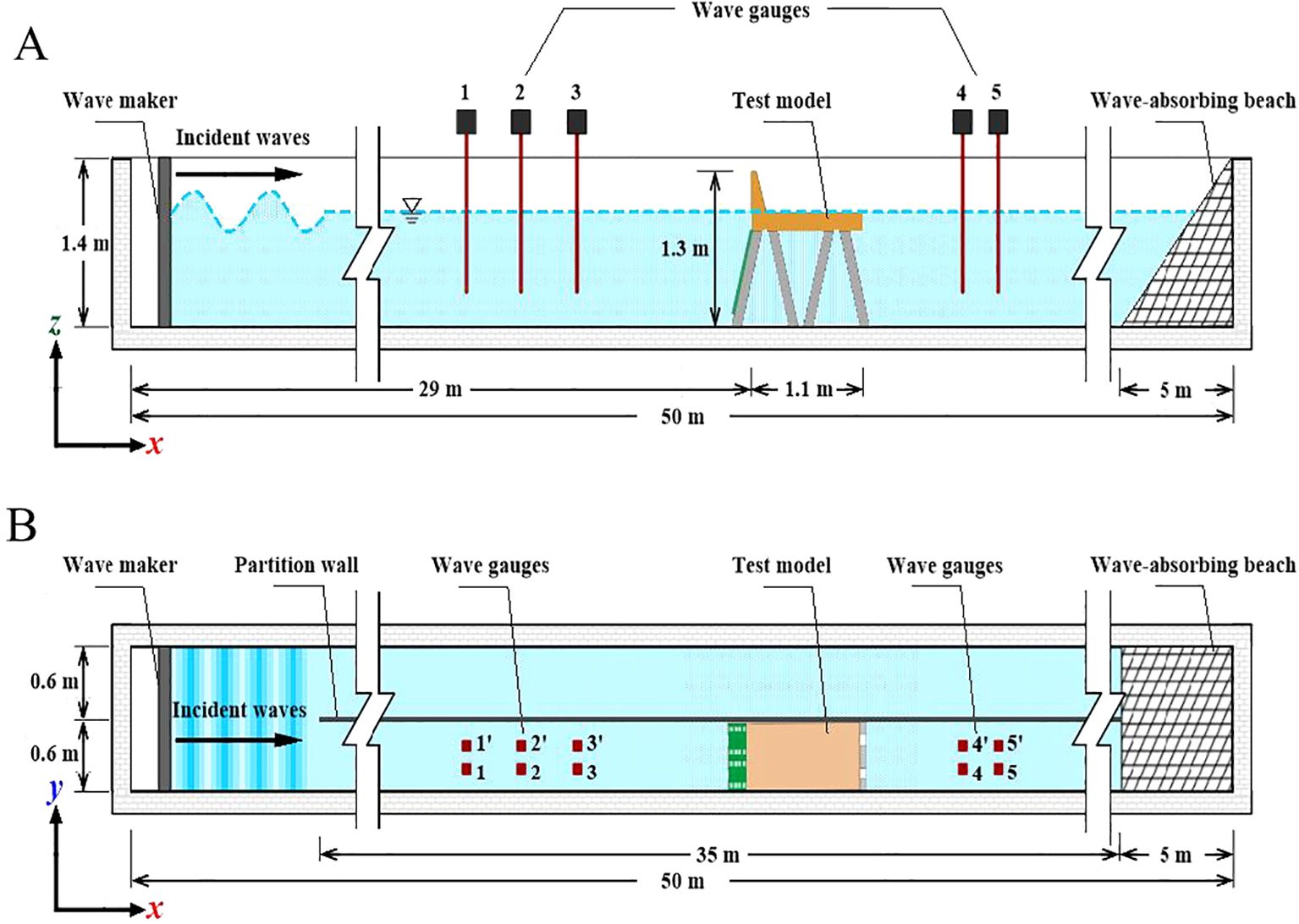
Figure 1. Schematic of the experimental setup for the physical model from (A) front view and (B) top view.
2.2 Model structure: the pile-supported permeable breakwaters
Figure 2 provides detailed information about the scaled models used in the experiment. The proposed breakwater model consists of three main components: a vertical-faced caisson, square cross-section piles, and inclined perforated plates with different layers and porosities. The Bohai Sea, as a marginal sea of the Pacific Ocean, is connected to the Pacific Ocean through the Bohai Strait. Along its coastline, significant large-scale ports such as Dalian, Tianjin, Huanghua, and Dongying are located. The substantial sediment carried by the Yellow River into the sea, combined with the historical hydrodynamic conditions of the Bohai Sea, results in significant siltation in coastal harbors and waterways each year. Additionally, these harbor facilities have to contend with soft ground conditions. Consequently, the novel breakwater design proposed in this paper is primarily researched within the context of the current marine environment. Miao et al. (2024) and Lv et al. (2014) indicate that the average water depth along the coast of the region ranges from 6.5 to 14 m, with average wave heights typically less than 5 s. Accordingly, this paper selects a prototype wave period of 3.5 to 7 s and a nearshore water depth of approximately 11 m for model design. The preliminary design of the in-situ model features a section width of about 13 m. Calculations based on the dispersion equation reveal that the wavelength of the prototype wave under the current conditions varies from 19.1 m to 61.7 m, with the ratio of most wavelengths to water depths being less than 0.5, indicating finite water depth waves. Consequently, employing the Froude similarity criterion and considering the practical scale limitations of the test flume, a model scale ratio of 1:12 was established to ensure that the Froude numbers of both the model and the prototype remained consistent. In the experimental setup, the water depth was set to 0.95 m, and the test wave period ranged from 1 to 2 s. Under prototype conditions, with a water depth of 11.4 meters and a wave period of 3.5 to 7 seconds, the calculated Froude numbers were equal, thereby satisfying the testing requirements. According to Halvorson and Huang (2024), when porosity remains constant, variations in the shape and size of the perforations have a minimal impact on wave energy dissipation performance. In this paper, the rectangular shape of the openings was selected based on these previous studies and the operational conditions of the laboratory, aiming to provide new insights and perspectives for the study of perforated structures. The porosity of an inclined perforated plate is defined as the ratio of the occupied area of the holes to the entire plate area. As depicted in Figure 2, the perforated plate is 600 mm wide and 720 mm high, respectively. The first plate has a rectangular hole with dimensions of 33.5 mm × 35.8 mm. The second plate has a hole size of 47.3 mm × 50.7 mm. Lastly, the third plate has a hole size of 58 mm × 62 mm. The corresponding porosities of these plates are ϵ=10%, 20%, and 30%, respectively. The corresponding porosities of the three plates are ϵ=10%, 20%, and 30%. The thickness of the porous plates is 0.006 m, which is considered negligible compared to the wavelengths considered in the experiment.
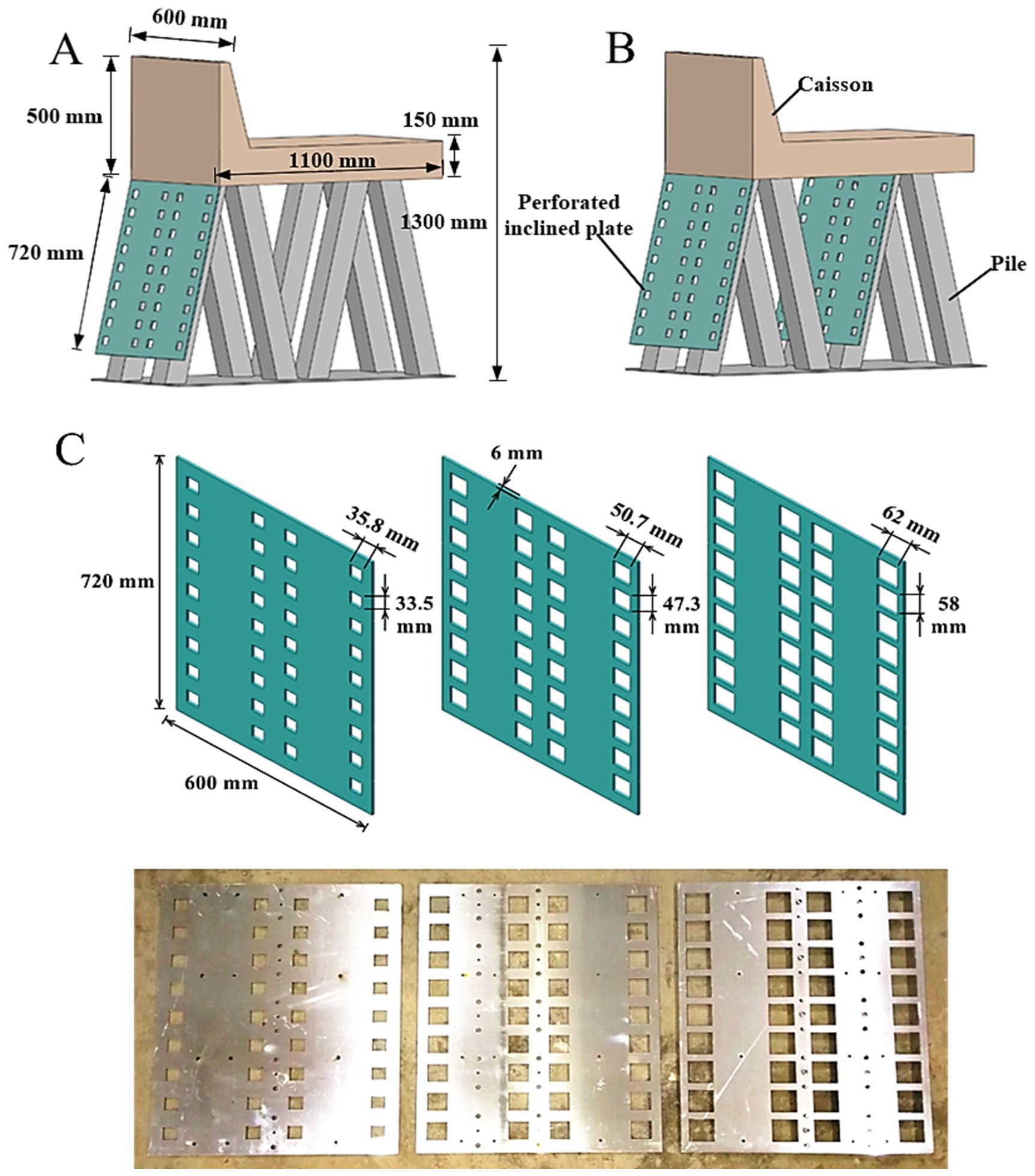
Figure 2. The model of the pile-supported breakwater with (A) a single-layer inclined perforated plate and (B) double-layer inclined perforated plates, and (C) perforated plates with different porosities.
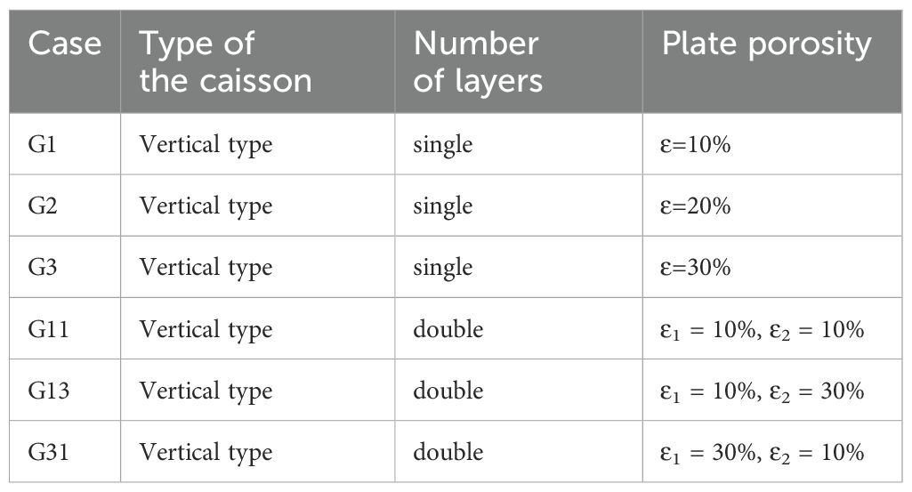
To ensure flexibility and adaptability, the porosity, number of layers, and arrangement of the inclined perforated plates were designed to be adjustable. For clarity, the models are named according to their number and combination, as presented in Table 1. The models with single-layer plates are named G1-G3, with the numbers representing the porosity of the perforated plates, where 1 corresponds to 10%. The model with double-layer plates is named G11-G31, and the sequence of numbers represents the combination of porosities. For example, G31 represents a combination of perforated plates with a front layer of 30% porosity and a back layer of 10% porosity.
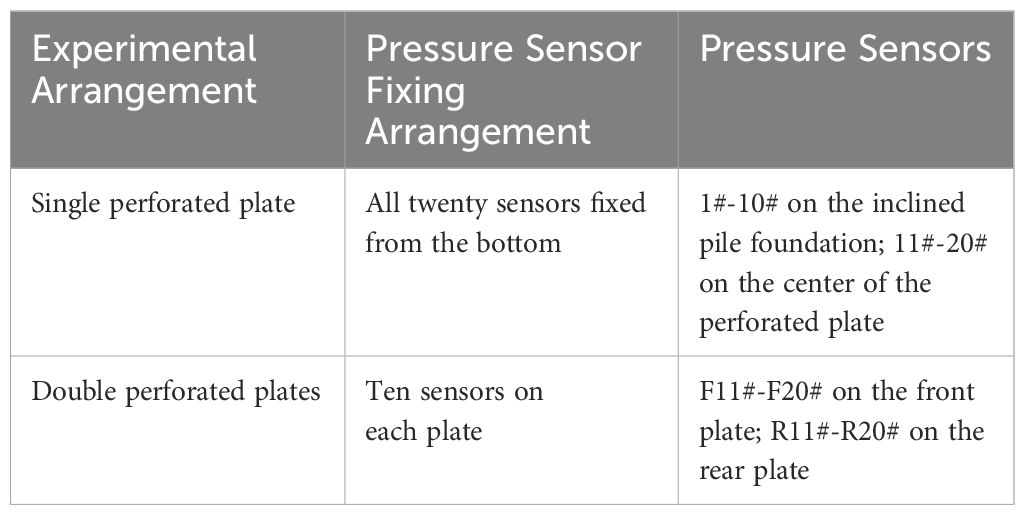
In the experimental setup of the pile-supported permeable breakwaters, as depicted in Figures 1A, B, the scaled models were positioned at a distance of 29 meters from the wave-maker. Furthermore, to more clearly illustrate the specific layout and modeling of the test, Figure 3 presents the physical modeling conducted under realistic conditions. To measure the wave elevation, several wave gauges were deployed in the flume. The experimental work involved investigating single and double perforated plates. For the study, a total of 20 pressure sensors were used, and their acquisition frequency was set at 100 Hz. These pressure sensors were crucial for understanding the dynamic pressures acting on the perforated plates, which were essential for the structural design of the breakwater. To optimize the placement of the pressure sensors, a specific arrangement was proposed, as outlined in Table 2. The pressure transducers were positioned at a constant distance from each other and evenly distributed across the measured section. This arrangement ensured comprehensive coverage of the pressure measurements along the plates. Figure 4 illustrates the arrangement of the pressure sensors. In Figure 4A, sensors 1# to 10# are positioned at the location of the pile foundation, while sensors 11# to 20# are located at the midpoint of the structure. In Figure 4B, for the double-layer case, F11# to F20# denote the sensors on the front perforated plate, and R11# to R20# indicate the sensors on the rear perforated plate, with F and R representing their respective locations. This nomenclature facilitates subsequent comparisons. In the experiment, a dimensionless parameter was used to represent the z-direction, which refers to the vertical direction. The dimensionless parameter was defined as z/D, where z represents the distance from the bottom of the water to a specific point, and D denotes the water depth. The baseline for z was set at the bottom of the water, with positive values indicating an upward direction. The dimensionless parameter z/D=1 represented the free water surface, while z/D=0 represented the bottom boundary. The range of the dimensionless parameter varied from 0.2313 to 0.9281, covering different heights within the water column.
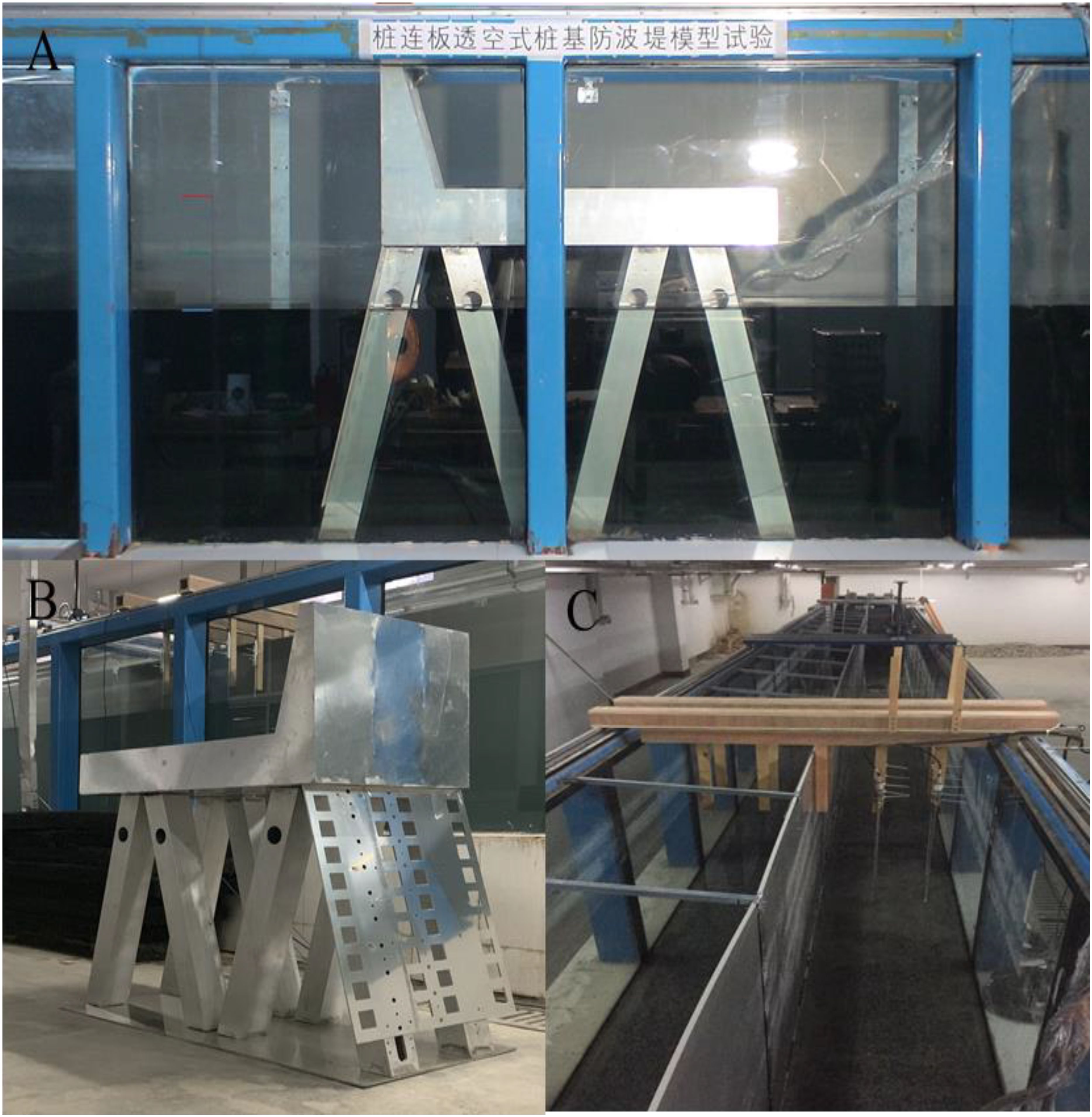
Figure 3. Experimental set-up in the hydrodynamics laboratory: (A) arrangement of the model in the wave flume and (B) model of breakwater for testing, and (C) the fixed bulkhead.
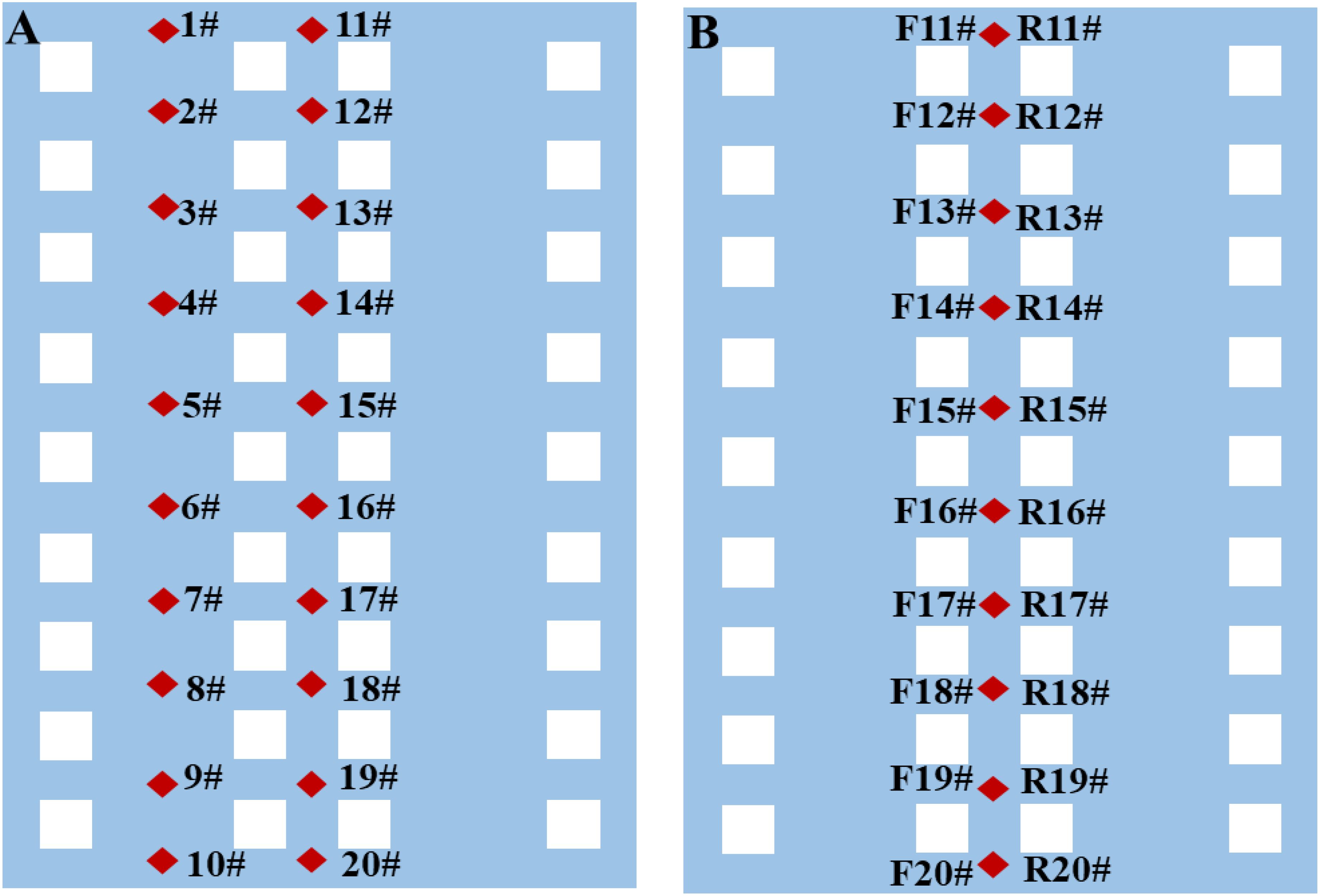
Figure 4. Arrangement of the pressure transducers on the perforated plate of (A) single-layer case, and (B) double-layer case.
2.3 Testing conditions
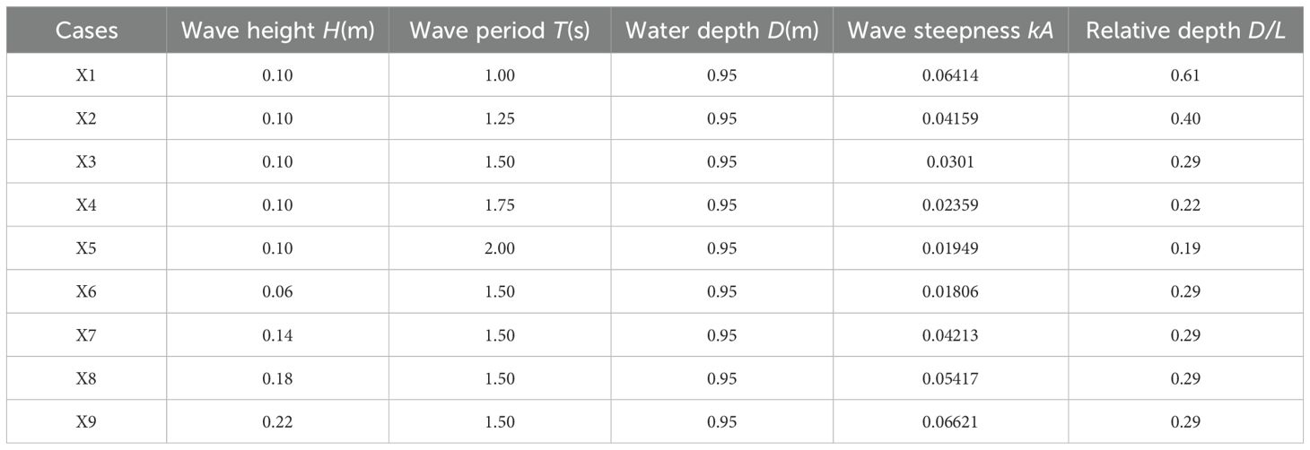
Laboratory investigations were conducted out for all the model configurations specified in Table 1. For each configuration, nine regular wave time series were used, and a total of 54 sets of tests were performed. A range of regular wave conditions were generated to simulate scaled physical wave conditions. The specific wave parameters are shown in Table 3. Throughout the experiments, the water depth (D) was maintained constant at 0.95 meters. The duration of each test was approximately 60 seconds. This duration was chosen to ensure that a sufficiently long wave time series was obtained, allowing for the establishment of stable wave conditions acting on the structure. By observing the wave behavior over this duration, researchers could gather accurate data on the wave-induced pressures and forces. To minimize experimental errors, each wave case measurement was repeated three times. The pressure and wave height measurements were recorded for each repetition, and the average of these measurements was used as the final result. This approach helped to enhance the reliability and accuracy of the experimental data.
3 Results
A comprehensive understanding of wave-induced dynamic pressures and forces on the structural elements of pile-supported breakwaters in regular wave conditions is essential for optimal structural design. This section presents sample dynamic pressure plots to elucidate the variations and fluctuations in dynamic pressure as a function of varying input conditions. The impacts of wave height, wave period, and the elevation of pressure sensors on the measured dynamic pressures are discussed.
3.1 Dynamic wave pressures
3.1.1 Time series of dynamic pressures acting on the perforated plates
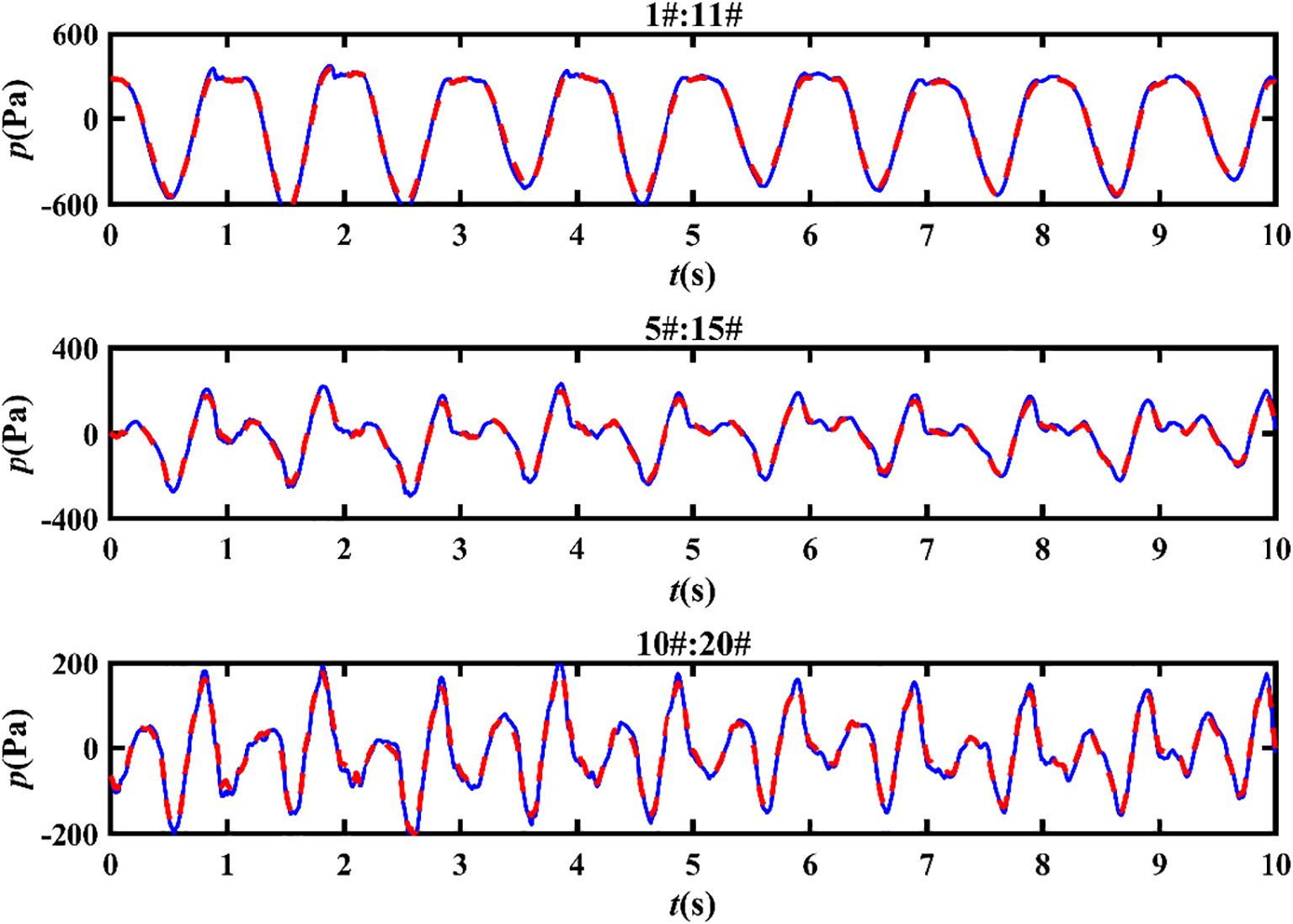
This subsection provides a brief analysis of pressure time series, focusing on the distribution of pressure along the perforated plate of model G1 during the X1-wave trials. Figure 5 provides a visual representation of this distribution. In the figure, two lines are depicted: a red dashed line indicating the instantaneous pressure time series at the pile foundation and a blue solid line representing the instantaneous pressure time series at the midpoint of the structure. Sensors 1#, 5#, and 10# represent the point pressure histories at the top, middle, and bottom positions of the pile foundation, respectively. Correspondingly, sensors 11#, 15#, and 20# capture the pressure histories at the midpoint of the structure. The objective of this analysis is to comprehend how wave pressures vary at different locations along the perforated plate. Results indicate that the wave pressures at the specified locations (pile foundation and midpoint) are nearly identical. This observation suggests that pressure measurements in the central region of the structure, particularly at locations 11#-20#, can be utilized for further analysis in subsequent sections. By concentrating on this central region, insights into the behavior of wave pressures and their effects on the perforated plates in pile-supported breakwaters can be gained.
Figure 5 demonstrates that the dynamic water pressure decreases gradually from the surface to the bottom of the perforated plate. This phenomenon occurs because wave energy tends to concentrate at the water surface. Furthermore, a distinct asymmetric bimodal phenomenon is observed at pressure sensors 15# and 20#. In the pressure time series, a peak value is observed initially, followed by a lower peak. This behavior aligns with the findings of Goda (1967). Moreover, Goda (1967) attributed this phenomenon to standing waves. After wave breaking, a transient shock load and a quasi-static load are exerted on the wave pressure, resulting in the extreme state of the bimodal phenomenon. The pressure-time history exhibiting bimodal peaks is considered a transitional stage in the transformation from regular wave pressure to broken wave pressure.
For the analysis of forces and pressures, pressure signals recorded by pressure transducers are examined over ten wave periods following a preliminary visual quality assessment. This duration ensures an adequate dataset to accurately capture wave-induced variations. The pressure time series serve as input for both force and pressure analysis, facilitating a comprehensive understanding of the dynamic pressures and forces acting on the structural elements of pile-supported breakwaters.
3.1.2 Effects of plate porosity on dynamic pressures
The wave-induced pressure acting on a structure can be characterized by defining the characteristic wave pressure. Various studies have considered different characteristic wave pressures to analyze the effects of waves on structures. Kisacik et al. (2012) and Ravindar et al. (2017) utilized the maximum characteristic wave pressure, Pmax, in their studies, while the significant wave pressure, P13%, was referred to in the structural design. Park et al. (2017) analyzed the Pmean, P1/3, P1/10, P1/50, P1/100, P1/250 and Pmax, respectively. In the study of Huang and Chen (2020), Pmax, P1%, P4%, P13%, and Pmean were calculated and analyzed for each wave train. In this paper, Figure 6 illustrates the pressure distribution of the wave pressure along the inclined perforated plate under X1-wave trials. The specific method for calculating pressure is as follows: first, positive pressures (including zero) and negative pressures are filtered out. The two pressure sequences are then sorted by absolute value, from largest to smallest. The top 33.3%, 10%, and 0.4% of the data with the highest absolute values are selected for averaging. This process yields the characteristic wave pressures P1/3, P1/10 and P1/250 under different test conditions. Additionally, it is important to note that the absolute values of the processed negative pressures should be multiplied by minus one to derive the characteristic negative pressure. Specifically, P1/3, P1/10 and P1/250 are plotted together. The figure reveals that the maximum wave pressure consistently occurs at the surface, with wave pressure decreasing rapidly with increasing water entry depth. Although the spatial distribution of different characteristic wave pressures varies in amplitude, the pattern of change exhibits significant similarity. Thus, this paper focuses on analyzing the effective wave pressure P1/3. Additionally, the pressure measured on a single perforated plate with 10% porosity is compared with the experimental data from Alkhalidi et al. (2015b) in Figure 7. The figure indicates that the vertical distribution patterns are similar. The differences in pressure magnitude can be attributed to two main factors: (1) the wave heights and periods in the literature are greater than those in the current tests, and (2) the literature calculates averages of the highest values, which can result in larger reported pressures. Nevertheless, the tests conducted in this study are considered relatively valid.
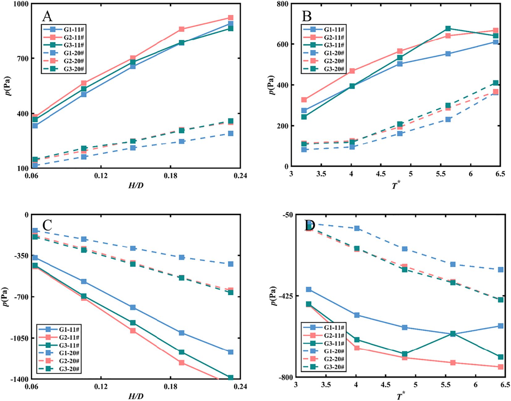
Figure 6. Comparison of the characteristic wave pressure versus H/D (A) positive pressure, (C) negative pressure and T* (B) positive pressure, (D) negative pressure at 2 pressure transducers: 11#, and 20# on model G1, G2, and G3.
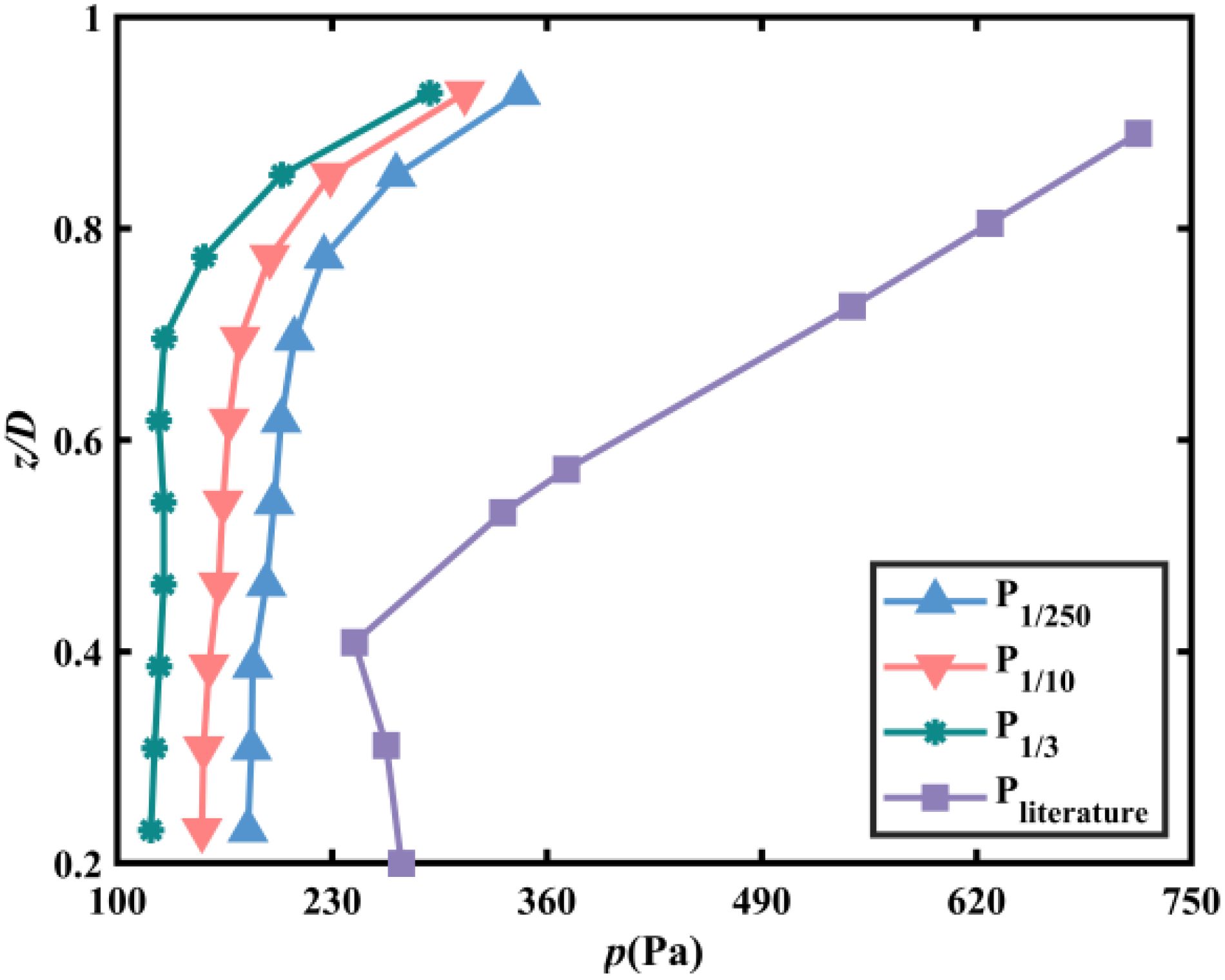
Figure 7. Comparisons of different characteristic wave pressure distributions along the perforated plate between the present experimental results and the results from Alkhalidi et al. (2015b).
Figure 6 presents the effects of perforated plate porosity on the dynamic pressure coefficients observed by pressure transducers 11# and 20# under varying wave heights and periods. Wave heights and periods are represented as dimensionless quantities. Furthermore, in the next section, the images will be plotted against these defined dimensionless variables, the relative height and the relative period , denoted uniformly by T*. The positive sign denotes shoreward pressure, while the negative sign indicates seaward pressure. The data indicate that point pressure increases with relative wave height and period; however, under the experimental conditions, the 10% porosity plate experiences lower pressure compared to the other conditions. The structures with 20% and 30% porosity encounter nearly identical pressures. This phenomenon differs from the findings of Alkhalidi et al. (2015b), indicating that the effect of porosity on the structure’s pressure is not limited to locations near the still-water surface. The hydrodynamic properties of a porous plate are typically characterized by the relationship between pressure changes within the plate and local velocity. Chen et al. (2024) examine the effect of porosity on the kinematic and dynamic characteristics of fluctuations near a vertical porous plate. Theoretical results comparing horizontal velocity profiles and dynamic pressure distributions on both the wave-facing and wave-backing sides are presented for three different analyses. The findings indicate that as porosity increases from 0.1 to 0.5, the horizontal velocity amplitude on the leeward side gradually increases while that on the windward side decreases. Nevertheless, the horizontal velocity on the windward side remains greater than that on the leeward side. Additionally, the dynamic pressure amplitude on the windward side approaches that of the leeward side as porosity increases. This is reasonable, as a higher porosity reduces the porous plate’s impact on fluid motion. Furthermore, the dynamic pressure on the windward side of the porous plate increases with rising porosity, which aligns with the horizontal velocity results derived from Bernoulli’s principle. This observation helps explain why the dynamic pressure is comparatively lower for 10% porosity than for higher porosity values in this study. Therefore, structural design must carefully consider that dynamic water pressure does not simply decrease with increasing porosity. Understanding the influence of porosity on dynamic water pressure is critical for optimizing the design and performance of perforated plate structures in coastal engineering applications.
3.1.3 Effects of plate configuration on dynamic pressures
The impact of plate configurations on dynamic pressures was investigated using Models G1, G11, G13, and G31, which feature various combinations of porous plates for comparative analysis. The geometric details of these models are documented in Table 1 and Figure 2.
Figure 8 illustrates the variation of characteristic wave pressure in relation to relative wave height and relative period, comparing pressures observed on a single-layer perforated plate, the front layer of Model G11, and the rear layer of the perforated plate. The figure indicates that larger dynamic pressures are recorded on the front plate of both single and double perforated plates, with the front plate of the double-layer plate exhibiting higher pressures than the single-layer plate. The rear plate experiences lower dynamic pressure, attributable to the shading effect of the front plate. For both the single-layer and front plate, the pressure distribution demonstrates a pronounced top-high and bottom-low pattern, although this trend is less evident for the rear plate. Furthermore, the difference in dynamic pressures between the plates becomes more pronounced under conditions of high wave heights and long periods, underscoring the significance of plate configurations in the design of perforated plate structures.
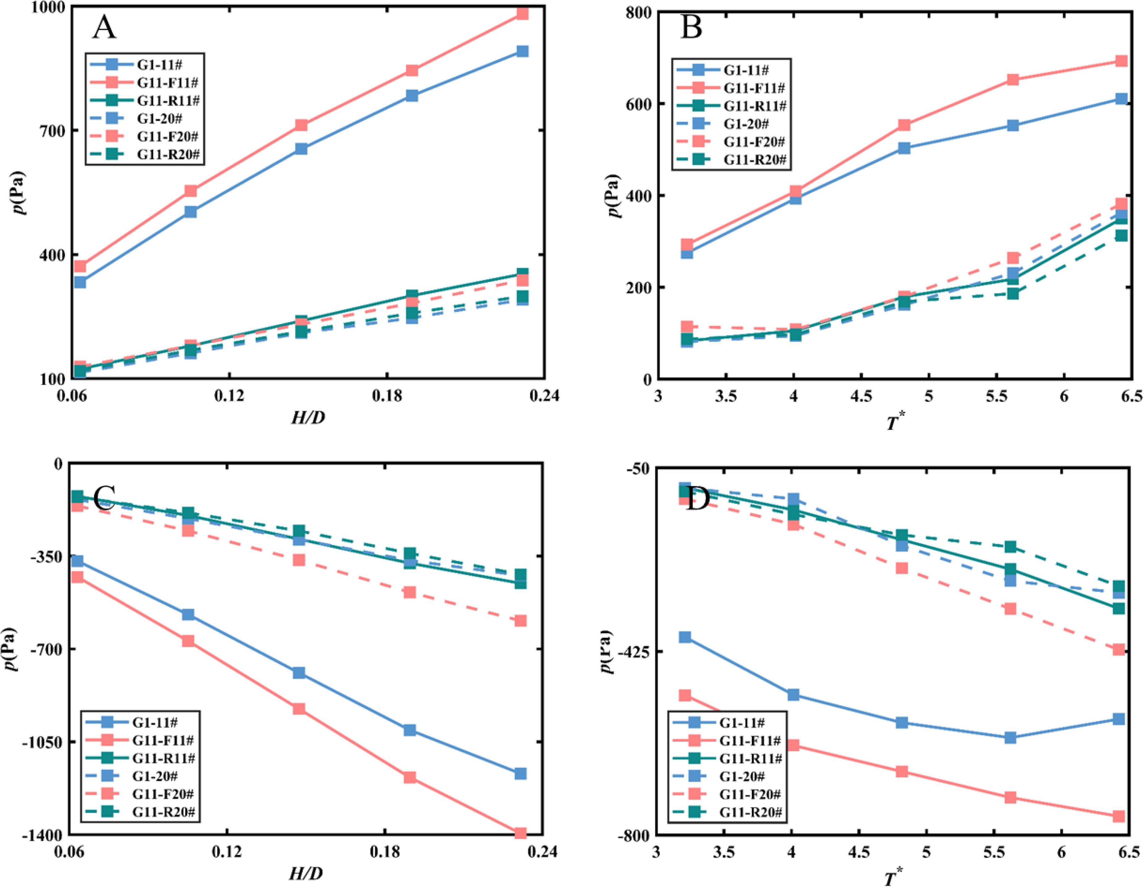
Figure 8. Comparison of the characteristic wave pressure versus H/D (A) positive pressure, (C) negative pressure and T* (B) positive pressure, (D) negative pressure at 2 pressure transducers: 11#, and 20# on model G1, and G11.
Figure 9 compares the dynamic pressures of the front and rear plates of Model G13 with a single-layer perforated plate under varying hydrodynamic conditions. The configuration of the double-layered plate mirrors the variation pattern shown in Figure 8. However, the reduced porosity of the rear plate modifies the distribution of dynamic pressure on the plate. Specifically, the dynamic pressure at the top of the perforated plate is slightly lower than that at the bottom. The observed phenomenon may be attributed to the redistribution of wave energy through the perforated plate. When waves approach a perforated plate, the energy of the wave is distributed across the plate’s structure. The perforations allow some of the water to flow through, but the energy is not uniformly transmitted. The horizontal flow velocity of the wave decreases with depth, leading to greater wave energy loss through the upper perforations. This results in a rapid decrease in flow velocity at the first layer of the plate. In contrast, the lower portion experiences smaller energy loss and less variation in flow velocity. Additionally, the spacing maintained from the bed allows for a higher flow rate of transmitted water. The water flow through the first layer of the plate undergoes vertical upward diffusion, impacting the bottom of the second layer and increasing the pressure at that location to some extent. A configuration with reduced porosity causes the water flow through the bottom perforations of the first layer to carry more energy, while the flow at the bottom of the second layer carries away relatively less energy. This differential energy distribution can lead to variations in pressure. Consequently, this may result in slightly lower pressure at the top of the leeward side of the plate compared to the bottom. Figure 10 depicts an arrangement with a high porosity front plate and a low porosity rear plate, revealing that the dynamic pressure on the front plate is comparable to that of the single-layer plate when subjected to positive wave pressure. The wave pressure at the bottom of the double-layer plate indicates that the front plate experiences higher pressures than the rear plate.
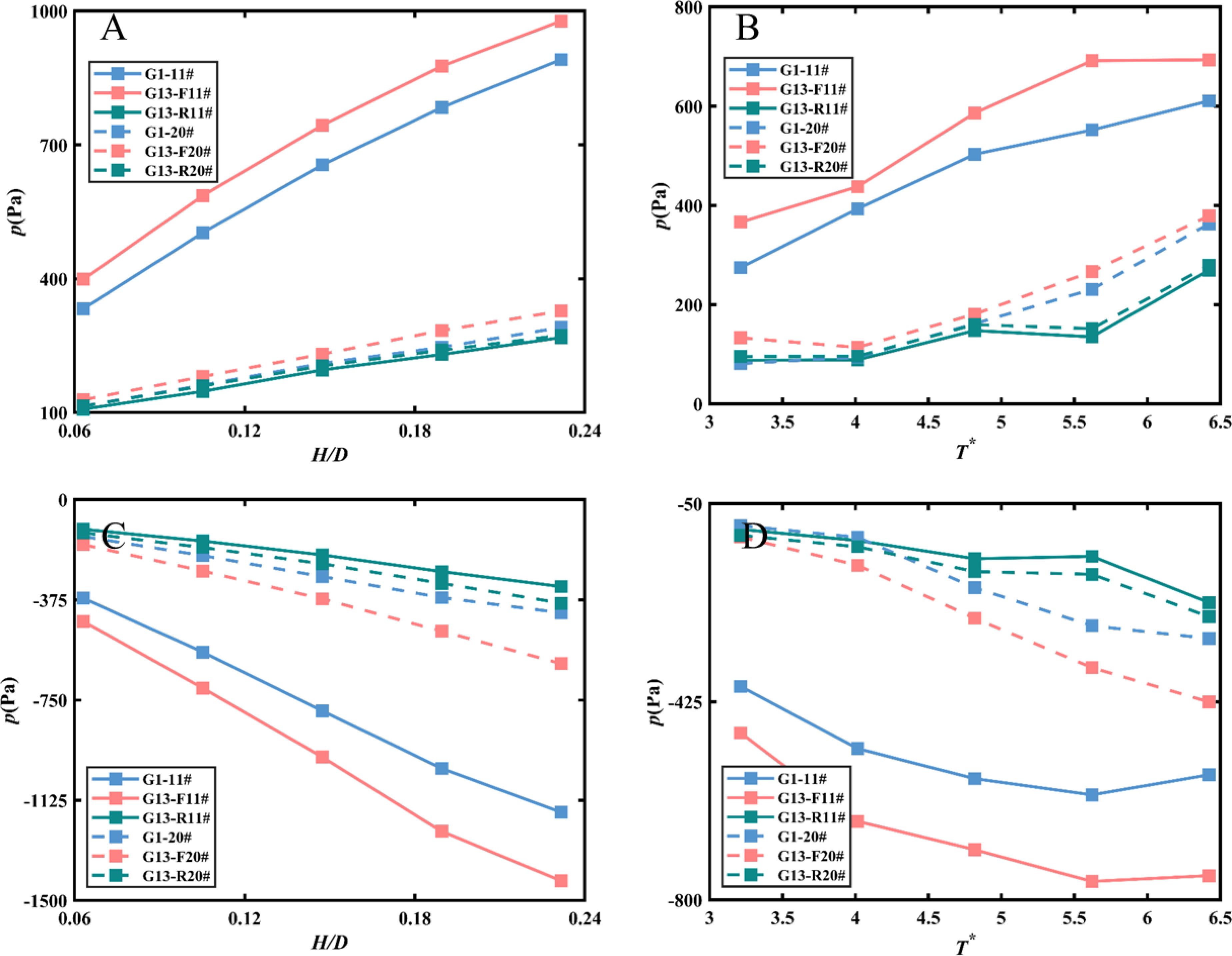
Figure 9. Comparison of the characteristic wave pressure versus H/D (A) positive pressure, (C) negative pressure and T* (B) positive pressure, (D) negative pressure at 2 pressure transducers: 11#, and 20# on model G1, and G13.
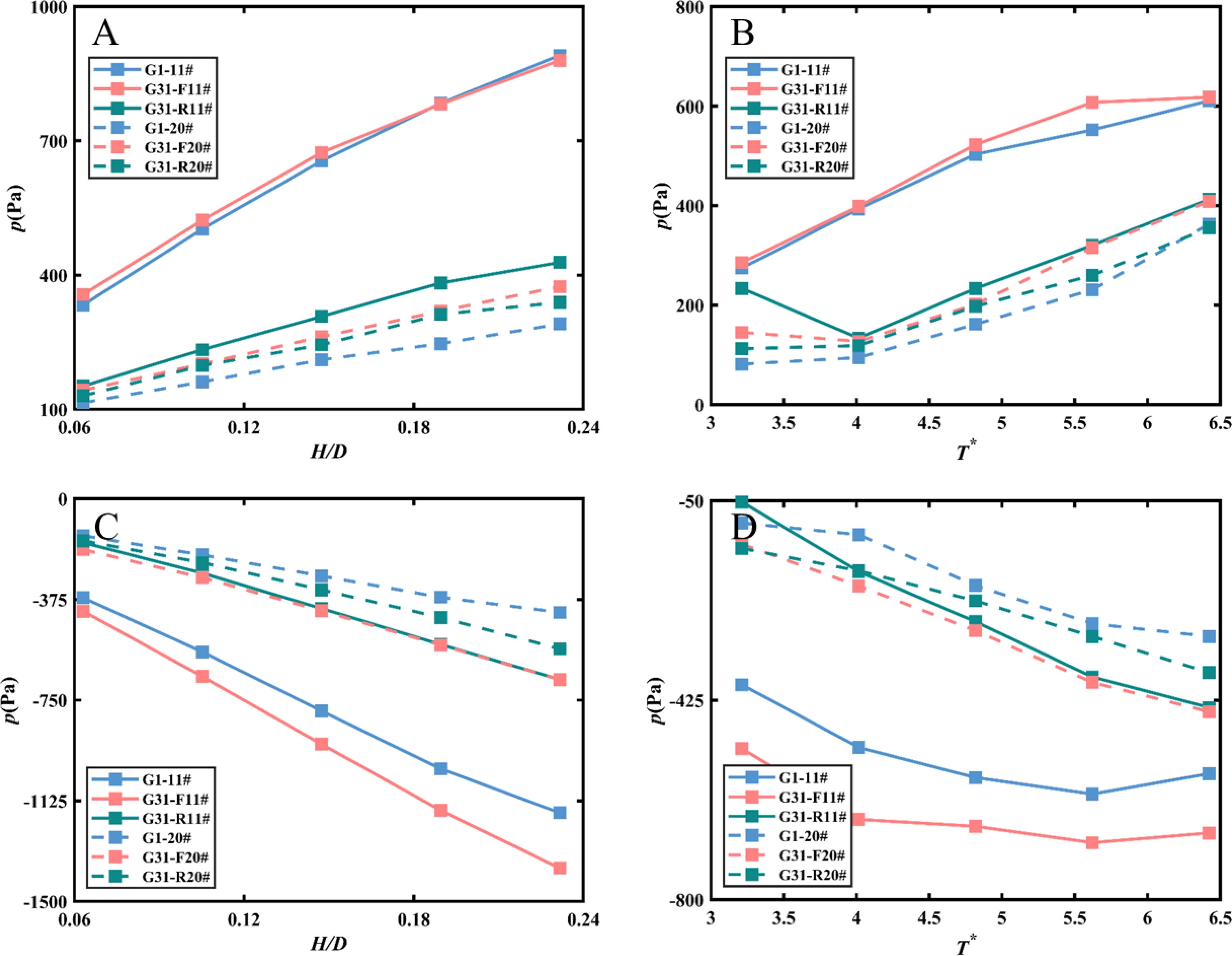
Figure 10. Comparison of the characteristic wave pressure versus H/D (A) positive pressure, (C) negative pressure and T* (B) positive pressure, (D) negative pressure at 2 pressure transducers: 11#, and 20# on model G1, and G31.
These observations clearly demonstrate that the configuration and porosity of both the front and rear plates significantly influence the dynamic pressures experienced by the perforated plate structure. Altering the porosity of the rear plate affects pressure distribution, while modifications to the front plate’s porosity result in changes to pressure levels. These findings highlight the critical importance of carefully designing and selecting plate configurations and porosities tailored to the desired performance and functionality of perforated plate structures in coastal engineering applications.
3.2 Wave forces
3.2.1 Effects of plate porosity on wave forces
The time series of experimentally measured pressures were used as input signals for the force analysis. For the analysis of the forces on the structure, for each test, the area of influence of each transducer is considered and the pressure signal is integrated to obtain a time series of forces on the structure. All point pressure sensors are uniformly distributed along the perforated plate, allowing for the calculation of point pressure radiation over a specific area based on this distribution. For simplification, the measured values from the sensors are considered as the average pressure amplitude over an equivalent area. Consequently, when a particular wave train is active, the instantaneous pressure readings at all positions are multiplied by the area of action and summed to determine the force on the perforated plate at that moment. This process generates a time series of forces corresponding to the current wave train. Similarly, the force data for a specific wave train is filtered to obtain the absolute values of the force sequence in descending order. The effective force F1/3 is then calculated by averaging the highest one-third of these absolute force values. Similar to the pressure-time series, the effective force F1/3 is considered in the following analysis and discussion.
Figure 11 displays the forces acting on the inclined perforated plate. The figure is divided into two parts: the first row represents the effect of variations in relative wave height and period on the forces under positive force conditions, while the second row illustrates the pattern of change under negative force conditions. The forces acting on the perforated plate reflect the pressure difference between the two sides of the plate. As the wave height and period increase, the velocity perpendicular to the plane of the plate also increases, resulting in higher pressure loss. Consequently, an increase in pressure loss leads to an increase in structural force. It can be observed from Figure 11 that an increase in both relative wave height and period corresponds to an increase in the structural force. Furthermore, increasing the porosity of the perforated plate results in a decrease in the applied force for all test conditions. This reduction in force is attributed to the increased porosity allowing wave energy to propagate more freely through the porous wall. Consequently, there is less wave impact on the wall, leading to a decrease in force exerted on the structure.
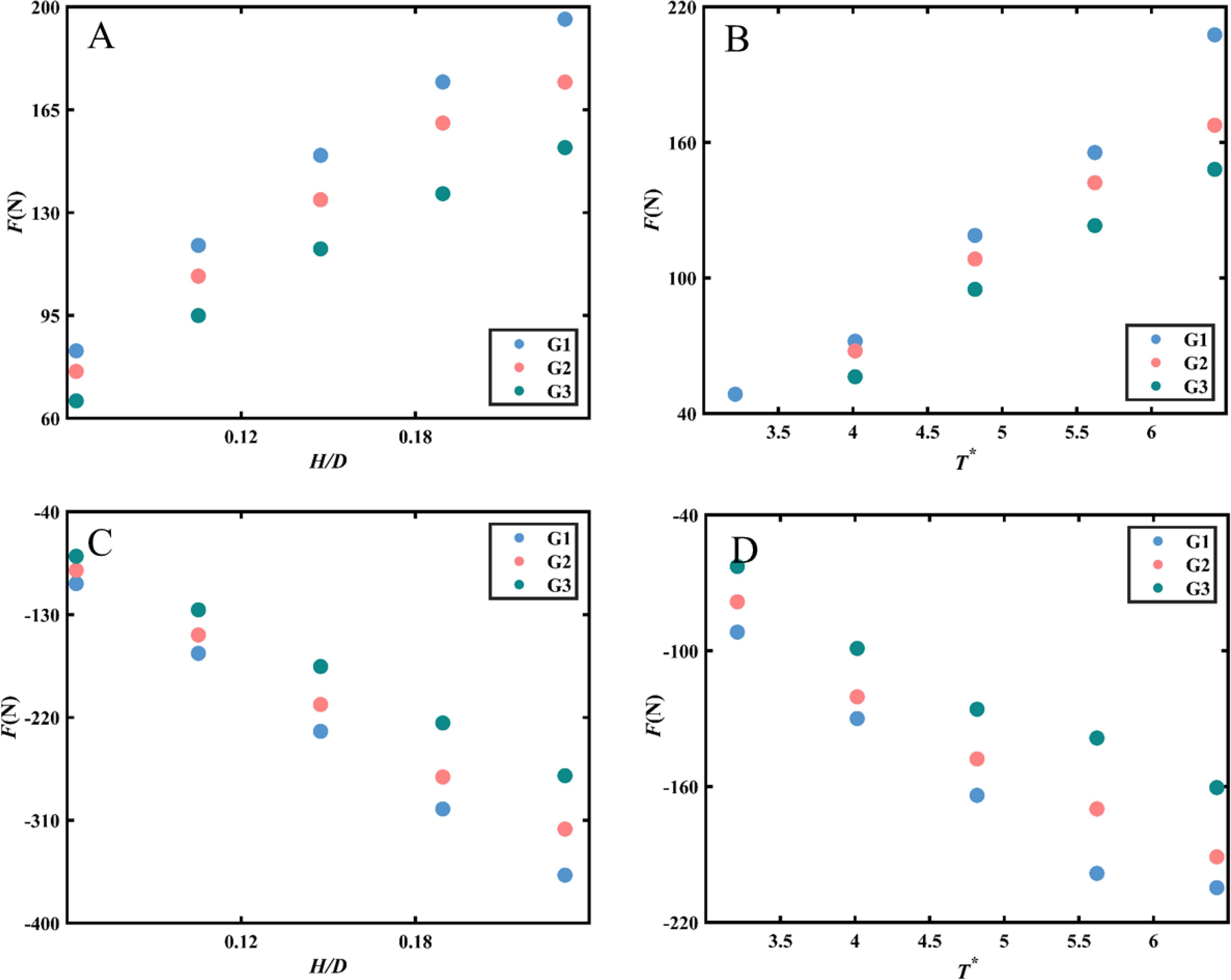
Figure 11. Effects of porosity on the variations of wave forces versus H/D (A) positive force, (C) negative force and T* (B) positive force, (D) negative force along the perforated plate of G1, G2, and G3.
3.2.2 Effects of plate configuration on wave forces
Figures 12–14 compare the forces on single-layer plates with those on models G11, G13, and G31, respectively. Figure 12 indicates that the force on the perforated plate increases with wave height and period. Notably, the force on the front plate of the double-layer configuration exceeds that of the single-layer plate, although this disparity diminishes as the wave period increases. Moreover, both forces on the front and rear plates of the double-layer configuration are significantly greater than those on the rear plate alone. The force on the rear plate exhibits less variation with wave height and period. This phenomenon aligns with the conclusions presented in Alkhalidi et al. (2015a) and Alkhalidi et al. (2015b). The front plate directly confronts incoming waves, which exert significant forces due to the momentum and energy carried by these waves. In a double-layer configuration, the rear plate is situated behind the front plate, forming a chamber-like structure. As waves pass through the front plate, some water flows into the space between the two plates, generating additional loading on the front plate. Specifically, the interaction of the water with the rear plate can induce turbulence and pressure fluctuations, further increasing the force exerted on the front plate. This interaction can lead to a phenomenon known as “wave trapping,” wherein energy is retained within the chamber formed by the two plates. This trapped energy can result in elevated pressure on the front plate, particularly during high-energy wave events. The flow dynamics within this chamber can produce higher localized pressures and forces, contributing to the overall loading experienced by the front plate. In contrast, a single-layer configuration does not include this additional layer that alters the water flow dynamics. In a single-layer setup, the front plate is solely subjected to direct wave impacts. Consequently, the forces experienced in this configuration are generally lower, as there is no rear plate to create additional pressure from trapped or interacting water. The absence of this secondary interaction results in a more straightforward distribution of forces on the front plate in a single-layer system. Figure 13 shows that increasing the porosity of the rear plate leads to a further reduction in the force acting on it, while the force on the front plate remains nearly equivalent to that of the single-layer plate. Therefore, it is imperative to design the front plate to be structurally stronger than the rear plate.
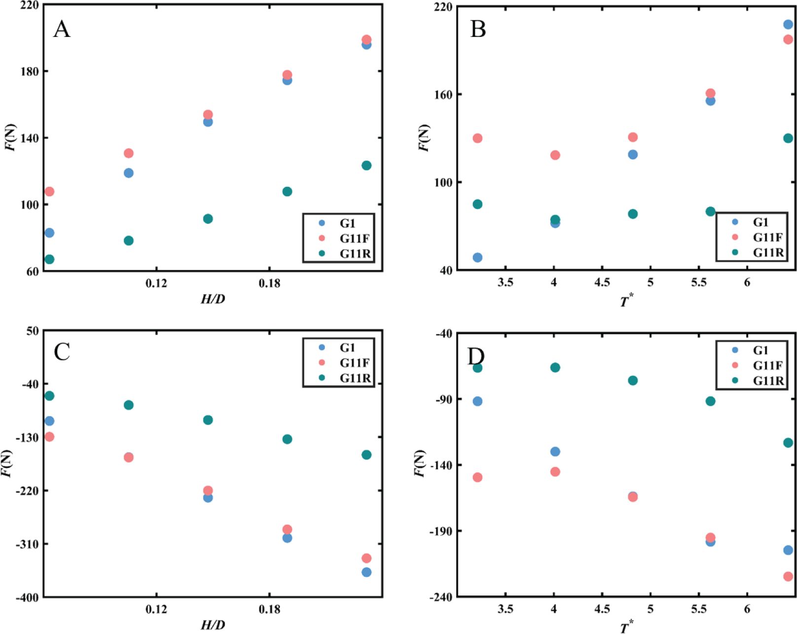
Figure 12. Effects of wall configurations on the variations of wave forces versus H/D (A) positive force, (C) negative force and T* (B) positive force, (D) negative force along the perforated plate of G1, G11F, and G11R.
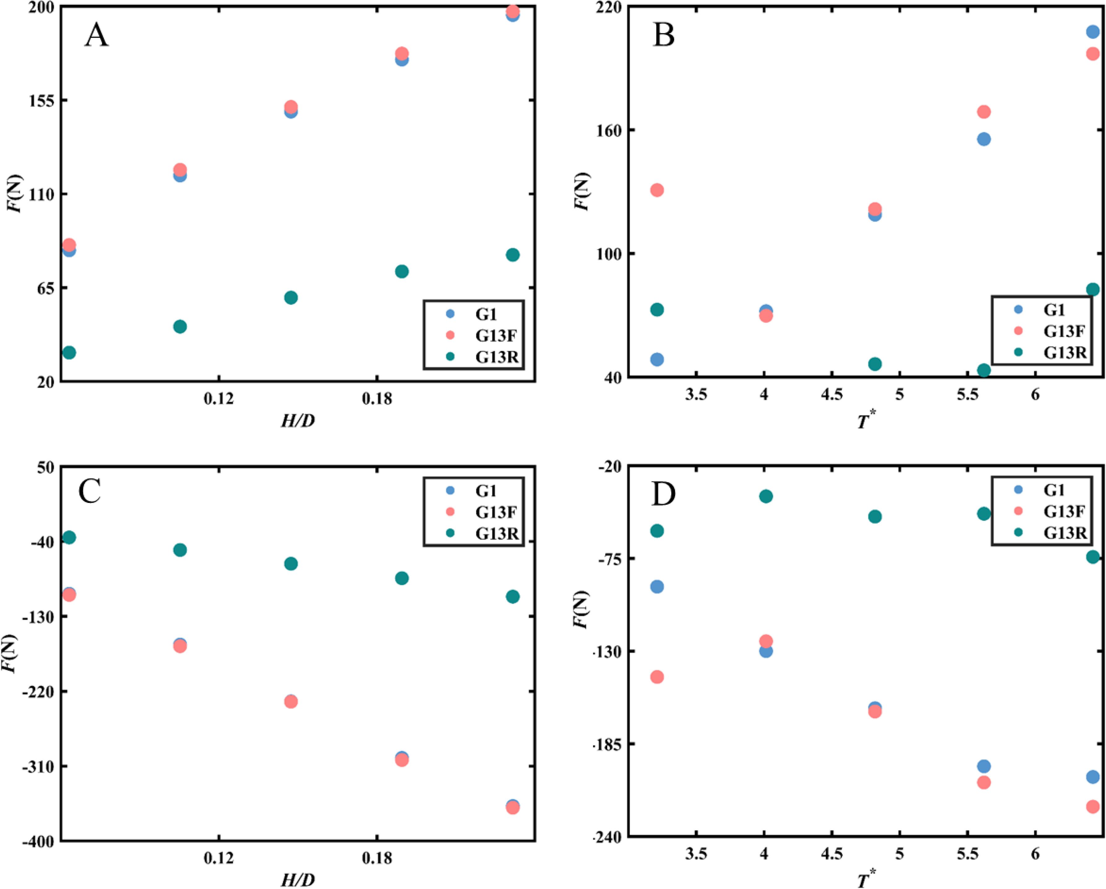
Figure 13. Effects of wall configurations on the variations of wave forces versus H/D (A) positive force, (C) negative force and T* (B) positive force, (D) negative force along the perforated plate of G1, G13F, and G31R.
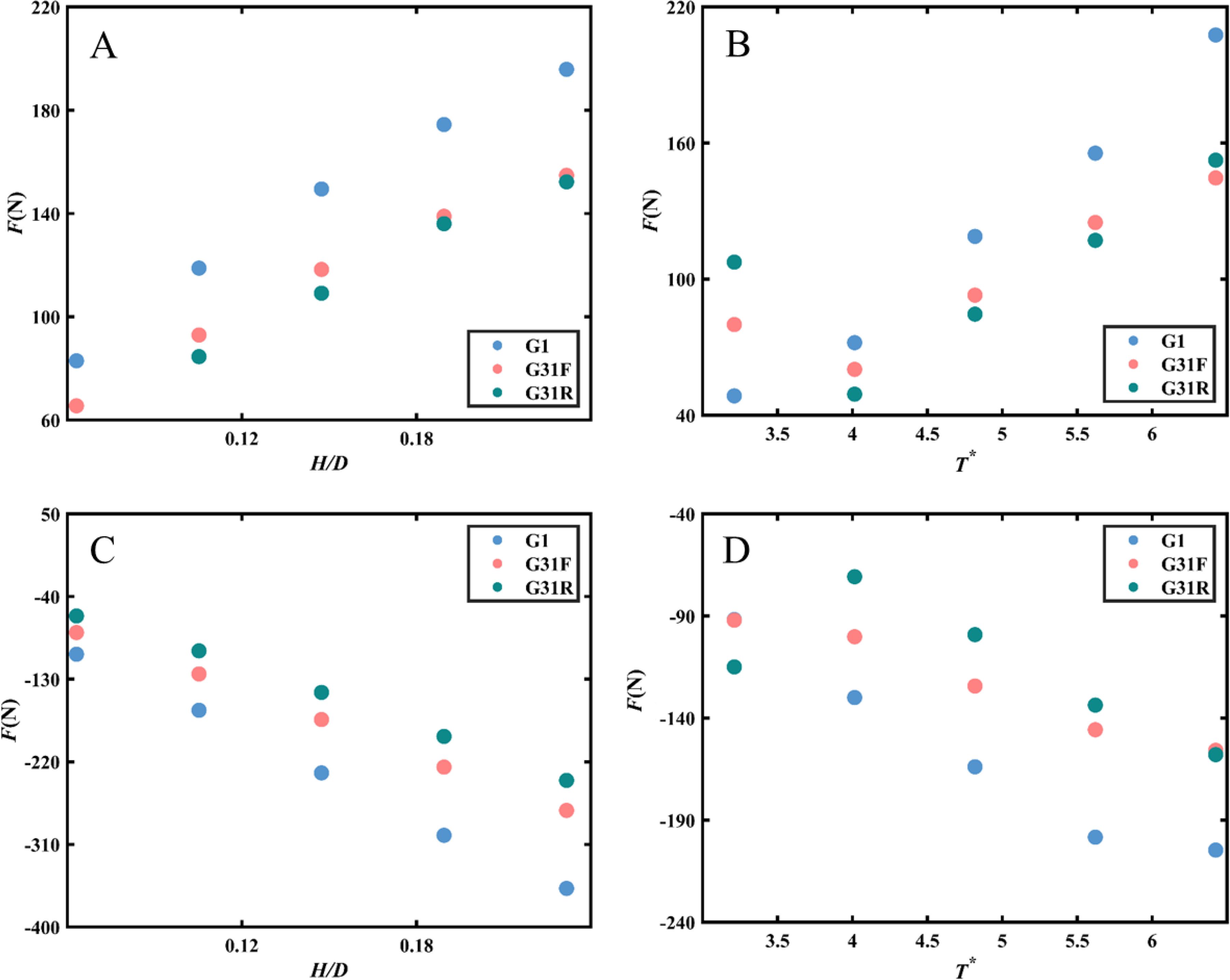
Figure 14. Effects of wall configurations on the variations of wave forces versus H/D (A) positive force, (C) negative force and T* (B) positive force, (D) negative force along the perforated plate of G1, G31F, and G31R.
Figure 14 illustrates the impact of progressively decreasing porosity from the front plate to the rear plate on wave-induced dynamic pressures. The current configuration of perforated plates significantly influences structural forces. Under the experimental conditions, the structural forces in double-layer plates are considerably lower than those in single-layer plates. Specifically, forces on the front plate can reach up to 70% of those on a single-layer plate, while the rear plate experiences forces up to 59% of those on a single-layer plate. This suggests that structural design can be optimized to reduce construction costs by increasing the porosity of the front plate rather than solely enhancing the thickness and strength of the plate. By strategically adjusting the porosity distribution along the perforated plate, engineers can achieve reduced stresses on the structure while significantly enhancing wave dissipation capacity.
In conclusion, the arrangement of Model G31 offers the advantage of reducing stresses on the structure while enhancing wave dissipation capacity. By carefully designing the porosity of the perforated plate in accordance with the force requirements of the structure, engineers can optimize the structural design and achieve cost savings.
4 Discussion
In order to illustrate the effect of porosity in single-layer perforated plates, three structures with different porosities were investigated. It was found that increasing porosity from 10% to 30% leads to a significant reduction in dynamic pressure and force on the perforated plate. These findings are consistent with previous studies by Alkhalidi et al. (2015b)., which indicated that incident waves passing through a porous medium primarily result in pressure loss. The wave forces on the structure are reflective of the pressure difference between the front and back of the plate. The intrinsic mechanisms underlying this phenomenon involve a combination of viscosity, inertia, and fluid turbulence. Under identical wave conditions, perforated plates with higher porosity experience smaller wave forces due to a reduced impact area. According to Alkhalidi et al. (2015b), porosity significantly influences dynamic pressure on the porous wall plate near the still water surface, although its impact is less pronounced near the seabed. This study demonstrates that porosity substantially affects the overall performance of the perforated plate. Therefore, in the design of perforated plates, porosity should be considered as a control parameter not only for wall plates near the still water surface but for the overall perforated plate.
Further examination of perforated plate configurations revealed that various combinations of porous plates were analyzed using Models G1, G11, G13, and G31, facilitating comparative analysis. Similar to Alkhalidi et al. (2015a) and Alkhalidi et al. (2015b), it was observed that the dynamic pressure on a single perforated plate or the front plate was significantly higher than that on the rear plate when the same porosity was used in the double-layer plate configuration. Forces on the rear plates in double-layer configurations were 20% to 60% lower than those on single-layer plates, with dynamic pressure uniformly distributed vertically. According to Neelamani and Al-Anjari (2021), few studies have been conducted on the effect of varying the porosity of each wall on the wave-induced dynamic pressure. This paper examined G13 with increasing porosity and G31 with decreasing porosity, revealing that a configuration with decreasing porosity not only improved wave dissipation performance but also reduced forces on the perforated plate. The forces on the front plate could reach up to 70% of those on a single-layer plate, while the rear plate experienced forces at approximately 59%. This suggests that design can be optimized through porosity configuration, ensuring structural efficiency while reducing costs.
It is important to note that this study focused on the dynamic pressures and forces of pile-supported permeable breakwaters. Certain simplifications and assumptions were made in the experimental design to elucidate general principles more clearly. For instance, only regular waves were considered to mitigate uncertainties arising from the randomness of real sea states. However, further research is necessary to explore the effects of irregular waves and structures with additional layers of perforated plates to derive broader conclusions. Additionally, the wave conditions addressed in this paper are primarily tailored for the nearshore region of the Bohai Sea. To enhance the general applicability of this study, future research will focus on a broader range of wave conditions.
5 Conclusions
This study conducted wave-flume tests to experimentally investigate the dynamic pressures and wave forces acting on pile-supported breakwaters with inclined perforated plates. The objective was to examine the effects of plate porosities and configurations on wave protection and structural design. The following conclusions were drawn:
1. Under the current test conditions, the force exerted on the perforated plate decreased as the porosity of the plate was varied from 10% to 30%. When utilizing a double-layer plate configuration with the same porosity, the dynamic pressure on the single-layer or front plate was significantly higher compared to the rear plate. The forces acting on the rear plate in the double-layer configuration were 20% to 60% less than those on the single-layer plate. The dynamic pressure on the rear plate exhibited a uniform vertical distribution.
2. Varying the porosity of the perforated plates at different locations had a significant effect on the structural forces. Gradually decreasing the porosity not only led to a considerable improvement in wave dissipation performance for the breakwater but also resulted in a substantial reduction in the force exerted on the perforated plate. Moreover, the forces acting on the front and back plates could reach approximately 70% of those experienced by single-layer plates.
3. Dynamic pressure and force decrease with increasing relative wave height and relative period. The changes are more pronounced near the still water surface than near the seafloor.
This study provides valuable insights for engineering applications and offers guidance for the development of similar structures. However, it is essential to recognize the limitations of this research and the necessity for further investigations, particularly regarding the effects of irregular waves and the impact of extreme conditions on structural safety.
Data availability statement
The original contributions presented in the study are included in the article/supplementary material. Further inquiries can be directed to the corresponding author.
Author contributions
ZL: Conceptualization, Data curation, Investigation, Methodology, Software, Supervision, Validation, Visualization, Writing – original draft, Writing – review & editing. RL: Conceptualization, Data curation, Investigation, Writing – review & editing, Methodology. ZW: Conceptualization, Formal analysis, Funding acquisition, Project administration, Supervision, Writing – review & editing, Methodology. BL: Conceptualization, Data curation, Formal analysis, Funding acquisition, Project administration, Writing – review & editing. HX: Conceptualization, Methodology, Supervision, Validation, Writing – review & editing. XS: Conceptualization, Methodology, Supervision, Validation, Writing – review & editing. XW: Conceptualization, Formal analysis, Investigation, Methodology, Supervision, Writing – review & editing. LS: Conceptualization, Methodology, Supervision, Formal analysis, Validation, Writing – review & editing.
Funding
The author(s) declare financial support was received for the research, authorship, and/or publication of this article. The authors would like to acknowledge the support of the National Natural Science Foundation of China (Grant No.52101338, No. 52201341) and 22-05-CXZX-04-04-25.
Conflict of interest
The authors declare that the research was conducted in the absence of any commercial or financial relationships that could be construed as a potential conflict of interest.
Publisher’s note
All claims expressed in this article are solely those of the authors and do not necessarily represent those of their affiliated organizations, or those of the publisher, the editors and the reviewers. Any product that may be evaluated in this article, or claim that may be made by its manufacturer, is not guaranteed or endorsed by the publisher.
References
Alkhalidi M., Alanjari N., Neelamani S. (2020). Wave interaction with single and twin vertical and sloped slotted walls. J. Mar. Sci. Eng. 8, (8). doi: 10.3390/jmse8080589
Alkhalidi M., Neelamani S., Al Haj Assad A. I. (2015a). Wave forces and dynamic pressures on slotted vertical wave barriers with an impermeable wall in random wave fields. Ocean Eng. 109, 1–6. doi: 10.1016/j.oceaneng.2015.08.025
Alkhalidi M., Neelamani S., Assad A. I. A. H. (2015b). Wave pressures and forces on slotted vertical wave barriers. Ocean Eng. 108, 578–583. doi: 10.1016/j.oceaneng.2015.08.044
Alsaydalani M. O., Saif M. A. N., Helal M. M. (2017). Hydrodynamic characteristics of three rows of vertical slotted wall breakwaters. J. Mar. Sci. Appl. 16, 261–275. doi: 10.1007/s11804-017-1427-5
Buccino M., Daliri M., Dentale F., Calabrese M. (2019). CFD experiments on a low crested sloping top caisson breakwater. Part 2. Anal. plume impact. Ocean Eng. 173, 345–357. doi: 10.1016/j.oceaneng.2018.12.065
Chen Q., Cui J., Feng X., Liu Y., Chen J. (2024). Comparative study of analytical models with linear and quadratic pressure drop conditions on a perforated plate in water waves. Phys. Fluids 36, 107130. doi: 10.1063/5.0230812
Chen Y.-k., Liu Y., Meringolo D. D., Hu J.-M. (2023). Study on the hydrodynamics of a twin floating breakwater by using SPH method. Coast. Eng. 179, 104230. doi: 10.1016/j.coastaleng.2022.104230
Cheng Y., Fu L., Dai S., Collu M., Ji C., Yuan Z., et al. (2022). Experimental and numerical investigation of WEC-type floating breakwaters: A single-pontoon oscillating buoy and a dual-pontoon oscillating water column. Coast. Eng. 177, 104188. doi: 10.1016/j.coastaleng.2022.104188
Cho I. H., Kim M. H. (2008). Wave absorbing system using inclined perforated plates. J. Fluid Mechanics 608, 1–20. doi: 10.1017/S0022112008001845
Dai J., Wang C. M., Utsunomiya T., Duan W. (2018). Review of recent research and developments on floating breakwaters. Ocean Eng. 158, 132–151. doi: 10.1016/j.oceaneng.2018.03.083
Fugazza M., Natale L. (1992). Hydraulic design of perforated breakwaters. J. Waterway Port Coastal Ocean Eng. 118, 1–14. doi: 10.1061/(ASCE)0733-950X(1992)118:1(1)
Goda Y. (1967). The fourth order approximation to the pressure of standing waves. Coast. Eng. Japan 10, 1–11. doi: 10.1080/05785634.1967.11924051
Halvorson B., Huang Z. (2024). Study of effects of perforation layouts on wave energy dissipation caused by a submerged perforated breakwater in front of a vertical seawall. Ocean Eng. 311, 119025. doi: 10.1016/j.oceaneng.2024.119025
Han M. M., Wang C. M. (2022). Potential flow theory-based analytical and numerical modelling of porous and perforated breakwaters: A review. Ocean Eng. 249, 110897. doi: 10.1016/j.oceaneng.2022.110897
He F., Huang Z. (2014). Hydrodynamic performance of pile-supported OWC-type structures as breakwaters: An experimental study. Ocean Eng. 88, 618–626. doi: 10.1016/j.oceaneng.2014.04.023
He F., Li J., Pan J., Yuan Z. (2023). An experimental study of a rectangular floating breakwater with vertical plates as wave-dissipating components. Appl. Ocean Res. 133, 103497. doi: 10.1016/j.apor.2023.103497
Huang J., Chen G. (2020). Experimental modeling of wave load on a pile-supported wharf with pile breakwater. Ocean Eng. 201, 107149. doi: 10.1016/j.oceaneng.2020.107149
Huang Z., Li Y., Liu Y. (2011). Hydraulic performance and wave loadings of perforated/slotted coastal structures: A review. Ocean Eng. 38, 1031–1053. doi: 10.1016/j.oceaneng.2011.03.002
Isaacson M., Baldwin J., Premasiri S., Yang G. (1999). Wave interactions with double slotted barriers. Appl. Ocean Res. 21, 81–91. doi: 10.1016/S0141-1187(98)00039-X
Ji C.-H., Suh K.-D. (2010). Wave interactions with multiple-row curtainwall-pile breakwaters. Coast. Eng. 57, 500–512. doi: 10.1016/j.coastaleng.2009.12.008
Ji C.-Y., Guo Y.-C., Cui J., Yuan Z.-M., Ma X.-J. (2016). 3D experimental study on a cylindrical floating breakwater system. Ocean Eng. 125, 38–50. doi: 10.1016/j.oceaneng.2016.07.051
Jin R., He M., Geng B., Zhang H., Liang D. (2024). SPH study of scale effects of perforated caissons. Ocean Eng. 310, 118665. doi: 10.1016/j.oceaneng.2024.118665
Kar P., Sahoo T., Behera H. (2019). Effect of Bragg scattering due to bottom undulation on a floating dock. Wave Motion 90, 121–138. doi: 10.1016/j.wavemoti.2019.04.011
Karthik Ramnarayan S., Sannasiraj S. A., Sundar V. (2020). “Hydrodynamic Performance of Pile Supported Breakwaters—A Review,” in APAC 2019. Eds. Trung Viet N., Xiping D., Thanh Tung T. (Singapore: Springer Singapore), 929–935. doi: 10.1007/978-981-15-0291-0_127
Karthik Ramnarayan S., Sundar V., Sannasiraj S. A. (2022). Hydrodynamic performance of concave front pile-supported breakwaters integrated with a louver wave screen. Ocean Eng. 254, 111394. doi: 10.1016/j.oceaneng.2022.111394
Kisacik D., Troch P., Van Bogaert P. (2012). Experimental study of violent wave impact on a vertical structure with an overhanging horizontal cantilever slab. Ocean Eng. 49, 1–15. doi: 10.1016/j.oceaneng.2012.04.010
Koraim A., Heikal E., Rageh O. (2011). Hydrodynamic characteristics of double permeable breakwater under regular waves. Mar. Structures - Mar. Struct. 24, 503–527. doi: 10.1016/j.marstruc.2011.06.004
Liang J.-M., Chen Y.-K., Liu Y., Li A.-J. (2022). Hydrodynamic performance of a new box-type breakwater with superstructure: Experimental study and SPH simulation. Ocean Eng. 266, 112819. doi: 10.1016/j.oceaneng.2022.112819
Liu X., Liu Y., Lin P., Li A.-J. (2021). Numerical simulation of wave overtopping above perforated caisson breakwaters. Coast. Eng. 163, 103795. doi: 10.1016/j.coastaleng.2020.103795
Liu X., Liu Y., Lin P., Wang D. (2023). Experimental and numerical studies of solitary wave interaction with perforated caisson breakwaters. Phys. Fluids 35, 057119. doi: 10.1063/5.0149420
Lv X., Yuan D., Ma X., Tao J. (2014). Wave characteristics analysis in Bohai Sea based on ECMWF wind field. Ocean Eng. 91, 159–171. doi: 10.1016/j.oceaneng.2014.09.010
Mallayachari V., Sundar V. (1994). Reflection characteristics of permeable seawalls. Coast. Eng. 23, 135–150. doi: 10.1016/0378-3839(94)90019-1
Miao Q., Yang J., Wang Z., Zhang Y., Yang Y., Wei G., et al. (2024). A study on wave climate variability along the nearshore regions of Bohai Sea based on long term observation data. Ocean Eng. 304, 117947. doi: 10.1016/j.oceaneng.2024.117947
Neelamani S., Al-Anjari N. (2021). Experimental investigations on wave induced dynamic pressures over slotted vertical barriers in random wave fields. Ocean Eng. 220, 108482. doi: 10.1016/j.oceaneng.2020.108482
Neelamani S., Al-Salem K., Taqi A. (2017). Experimental investigation on wave reflection characteristics of slotted vertical barriers with an impermeable back wall in random wave fields. J. Waterway Port Coastal Ocean Eng. 143, (4). doi: 10.1061/(ASCE)WW.1943-5460.0000395
Neelamani S., Vedagiri M. (2002). Wave interaction with partially immersed twin vertical barriers. Ocean Eng. 29, 215–238. doi: 10.1016/S0029-8018(00)00061-5
Nishad C. S., Vijay K. G., Neelamani S., Raja Sekhar G. P. (2024). Dual boundary element analysis for a pair of inverted T-type porous barriers having nonlinear pressure drop. Waves Random Complex Media 34, 1770–1794. doi: 10.1080/17455030.2021.1948145
Özgür Kirca V.Ş., Sedat KabdaŞLi M. (2009). Reduction of non-breaking wave loads on caisson type breakwaters using a modified perforated configuration. Ocean Eng. 36, 1316–1331. doi: 10.1016/j.oceaneng.2009.09.003
Park H., Tomiczek T., Cox D. T., van de Lindt J. W., LoMonaco P. (2017). Experimental modeling of horizontal and vertical wave forces on an elevated coastal structure. Coast. Eng. 128, 58–74. doi: 10.1016/j.coastaleng.2017.08.001
Rao S., Shirlal K. G., Varghese R. V., Govindaraja K. R. (2009). Physical model studies on wave transmission of a submerged inclined plate breakwater. Ocean Eng. 36, 1199–1207. doi: 10.1016/j.oceaneng.2009.08.001
Ravindar R., Sriram V., Schimmels S., Stagonas D. (2017). Characterization of breaking wave impact on vertical wall with recurve. ISH J. Hydraulic Eng. 25, 153–161. doi: 10.1080/09715010.2017.1391132
Takahashi S. (2002). Design of vertical breakwaters. Marine Environment and Engineering Department, Port and Airport Research Institute, Nagase, Yokosuka, Japan, Revised version 2.1. doi: 10.1142/9789814282413_0004
Teng B., Zhang X. T., Ning D. Z. (2004). Interaction of oblique waves with infinite number of perforated caissons. Ocean Eng. 31, 615–632. doi: 10.1016/j.oceaneng.2003.08.001
Vijay K. G., Neelamani S., Sahoo T. (2019). Wave interaction with multiple slotted barriers inside harbour: Physical and numerical modelling. Ocean Eng. 193, 106623. doi: 10.1016/j.oceaneng.2019.106623
Vijay K. G., Neelamani S., Sahoo T., Al-Salem K., Nishad C. S. (2022). Scattering of gravity waves by a pontoon type breakwater with a series of pervious and impervious skirt walls. Ships Offshore Structures 17, 130–142. doi: 10.1080/17445302.2020.1827630
Vijay K. G., Nishad C. S., Neelamani S., Sahoo T. (2020). Gravity wave interaction with a wave attenuating system. Appl. Ocean Res. 101, 102206. doi: 10.1016/j.apor.2020.102206
Keywords: pile-supported breakwater, perforated plates, wave forces, dynamic pressures, experimental investigation
Citation: Li Z, Liu R, Wang Z, Liang B, Xia H, Sun X, Wang X and Shi L (2024) Wave forces and dynamic pressures on pile-supported breakwaters with inclined perforated plates under regular waves. Front. Mar. Sci. 11:1499685. doi: 10.3389/fmars.2024.1499685
Received: 23 September 2024; Accepted: 18 November 2024;
Published: 04 December 2024.
Edited by:
Harekrushna Behera, National Taiwan Ocean University, TaiwanReviewed by:
K. G. Vijay, Indian Institute of Technology Madras, IndiaPrakash Kar, Dalian University of Technology, China
Copyright © 2024 Li, Liu, Wang, Liang, Xia, Sun, Wang and Shi. This is an open-access article distributed under the terms of the Creative Commons Attribution License (CC BY). The use, distribution or reproduction in other forums is permitted, provided the original author(s) and the copyright owner(s) are credited and that the original publication in this journal is cited, in accordance with accepted academic practice. No use, distribution or reproduction is permitted which does not comply with these terms.
*Correspondence: Rui Liu, bGl1cnVpMDgyMEAxNjMuY29t
 Ziwang Li
 Rui Liu
 Zhenlu Wang
 Bingchen Liang1,3
 Haofeng Xia
 Luming Shi