- 1School of Naval Architecture and Maritime, Zhejiang Ocean University, Zhoushan, China
- 2School of Naval Architecture, Ocean & Civil Engineering, Shanghai Jiao Tong University, Shanghai, China
- 3Institute of Sustainable and Autonomous Maritime Systems, University of Duisburg-Essen, Duisburg, Germany
- 4College of Mechanical and Marine Engineering, Beibu Gulf University, Qinzhou, China
It has been known that the cross-sectional shape of a column oscillator significantly influences its vibrational characteristics and energy conversion capacity, and can alter the nature of flow-excited vibration (FIV). Whether the addition of appendages to oscillators with different cross-sectional shapes enhances energy conversion capacity remains uncertain. In this study, the vibration characteristics and energy capture capabilities of an elastically supported oscillator with a semicircular appendage, suitable for low-speed seafloor current environments, are investigated. Experiments were conducted at zero degrees incidence for Reynolds numbers ranging from 5.041 × 10³ to 7.562 × 10⁴, resulting in turbulent wake conditions. The hydrodynamic properties of the oscillators were evaluated through statistical analysis, Proper Orthogonal Decomposition (POD), and vortex core identification of Particle Image Velocimetry (PIV) fields. The energy capture capability of the oscillator was assessed through statistical analysis of its vibration displacement, frequency, and amplitude. The study's results indicate that an oscillator with symmetric sharp attachments and without vortex reattachment is favorable for galloping with self-excitation. Under equivalent conditions, the Circular-T-shaped oscillator demonstrates superior energy conversion capacity compared to existing models, with the galloping branch being the most efficient for energy conversion; the peak efficiency is 24.5% (Ur = 14.5). This study provides some baseline data and optimization solutions for flow-induced motion power generation.
1 Introduction
In an era characterized by increasing energy demands and environmental concerns, the exploration of alternative energy sources has gained paramount importance. Among these sources, marine energy, with its vast untapped potential, has garnered significant attention in recent years (Kim et al., 2021). The utilization of marine energy promises a sustainable and renewable power source (Rostami and Armandei, 2017). As the demand for clean energy solutions continues to rise, the harnessing of hydrodynamic energy from the flow-induced motion (FIV) harnessing of hydrodynamic energy from the flow-induced motion (FIV) of oscillators emerges as a promising avenue (Bernitsas et al., 2008; Barrero-Gil et al., 2012). The harnessing of renewable energy from ocean currents is underpinned by notable advantages. This has prompted dedicated research initiatives (Han et al., 2023). Specifically, a device predicated on a flow-induced motion energy conversion system (FIMECS) has been introduced as a means to capture and extract energy from ocean currents, particularly under conditions characterized by low starting flow velocities (Mehmood et al., 2013).
FIV power generation (Blevins, 1979; Bishop and Hassan, 1964), a subset of marine energy harvesting, presents an innovative approach to converting the kinetic energy of water currents into electrical power (Gu et al., 2020). This technology holds immense promise due to its inherent efficiency and environmental compatibility. However, it is essential to recognize that the energy utilization efficiency of traditional cylindrical oscillators employed in FIV power generation could be further optimized (Khalak and Williamson, 1999). This optimization is pivotal in enhancing the feasibility and competitiveness of marine energy as a sustainable power source. Despite the immense potential of marine energy, the current utilization rate of ocean current energy through FIV remains relatively low (Park et al., 2023). This underutilization highlights a research gap in the field, necessitating a deeper investigation into enhancing energy conversion efficiency (Allen and Smits, 2001; Wang et al., 2021). The current state of FIV power generation predominantly relies on cylindrical oscillators (Norberg, 2003). While this approach has shown some promise, its energy utilization efficiency remains suboptimal (Opinel and Srinil, 2020). Therefore, there is a pressing need to explore alternative oscillator shapes and configurations that can maximize power generation (Ding et al., 2015). Traditional cylindrical oscillators, although effective to some extent, suffer from inherent inefficiencies in harnessing the full potential of FIV. These inefficiencies can be attributed to the limited exploration of wake vortex formations and boundary layer separations (Bearman, 1984; Facchinetti et al., 2004), which play a crucial role in energy conversion (Kandasamy et al., 2016).
The traditional circular cross-section has been found insufficient to significantly enhance power generation efficiency. Consequently, there is a growing focus on oscillators with non-circular cross-sectional shapes to improve energy extraction from fluid dynamic vibrations (Narendran et al., 2016). This occurs because conventional circular cross-section oscillators primarily exhibit a single vortex-excited vibration response. The phenomenon involves the structure vibrating periodically due to alternating vortex shedding generated by fluid flowing around the object's surface (Hsieh et al., 2017). In contrast, some non-circular cross-section oscillators exhibit both vortex-excited vibration and galloping, primarily caused by lift instability, representing two typical rheological vibration phenomena. The main cross-section types studied for non-circular cross-section oscillators are square, triangular, hexagonal, trapezoidal, and T-shaped (Zhang et al., 2022). The study of non-circular cross-section oscillators has led to examining their responses at different angles of attack, with results indicating that the angle of attack affects the oscillatory response of these oscillators (Zheng et al., 2022). In addition to the typical non-circular geometrical cross-sectional shapes, research on modified circular cross-sections has implemented passive turbulence control (PTC) in oscillators, enhancing lift by modifying boundary layer separation. Furthermore, a study of an oscillator with two symmetrically arranged rod attachments added to a circular cross-section demonstrated effective performance during galloping (Wang et al., 2020).
Due to the nonlinear galloping behavior of fluid flowing over the surface of a non-circular oscillator structure, complex and unstable forces are generated on the surface by vortices. This leads to the oscillator exhibiting vortex-induced vibrations (VIV) behavior (Williamson and Govardhan, 2004). Consideration is also given to the fact that the oscillations of the oscillator, triggered by the incoming flow, act to influence the flow field. Therefore, the visualization and analysis of the flow field in the vicinity of the oscillator are of importance (Eshbal et al., 2019). So far, the vibration problems of oscillators with typical geometrical cross sections have been relatively comprehensively studied. However, the effect of a typical non-circular cross-section combined with the addition of two symmetrically arranged rod attachments to the oscillator on FIV is Still not enough research. There is a lack of necessary experimental data support, visualization, and analysis for the study of these new cross-sectional shape oscillators.
The PIV technique enables the visualization and analysis of tail vortex formation and boundary layer separation complexity (Watine et al., 2023). POD helps extract essential information from the data, accurately capturing the non-constant structure of the flow process and the typical modes with the same main frequency of lift. Combined, they form a powerful analytical toolset. The flow of an instantaneous velocity field over a large planar region is measured using PIV (Xu et al., 2009). PIV provides a "snapshot", making it suitable for describing and understanding large-scale non-stationary motions compared to laser Doppler anemometry (LDA), which struggles to distinguish between velocity fluctuations caused by turbulence and those due to periodic changes in large-scale eddies (McClure et al., 2019). Proper Orthogonal Decomposition (POD), founded on the principle of principal orthogonality (PO), is a technique designed for data degradation and pattern extraction. While Principal Component Analysis (PCA) is frequently utilized for data dimensionality reduction, it also relies on the principle of PO. However, PCA is typically applied to analyze independently and identically distributed data, with the objective of identifying the direction of maximum variance, primarily focusing on static datasets. In contrast, POD is predominantly used for analyzing dynamic data over time, aiming to extract the primary dynamic modes present in the data. It is commonly employed in time series analysis (Rashidi et al., 2016). Therefore, the POD chosen in this paper is more suitable for extracting the main modes from complex temporal or spatial datasets and identifying the main dynamic features or flow patterns in the data. In this paper, a visualization and analysis method that combines PIV and POD is used to simultaneously address the problem of unclear identification of the flow field pattern near the oscillator in FIV experiments and the problem of unclear changes in the boundary layer, unloading vortices, and trailing vortices produced by the new cross-sectional oscillator compared to the traditional cross-sectional oscillator.
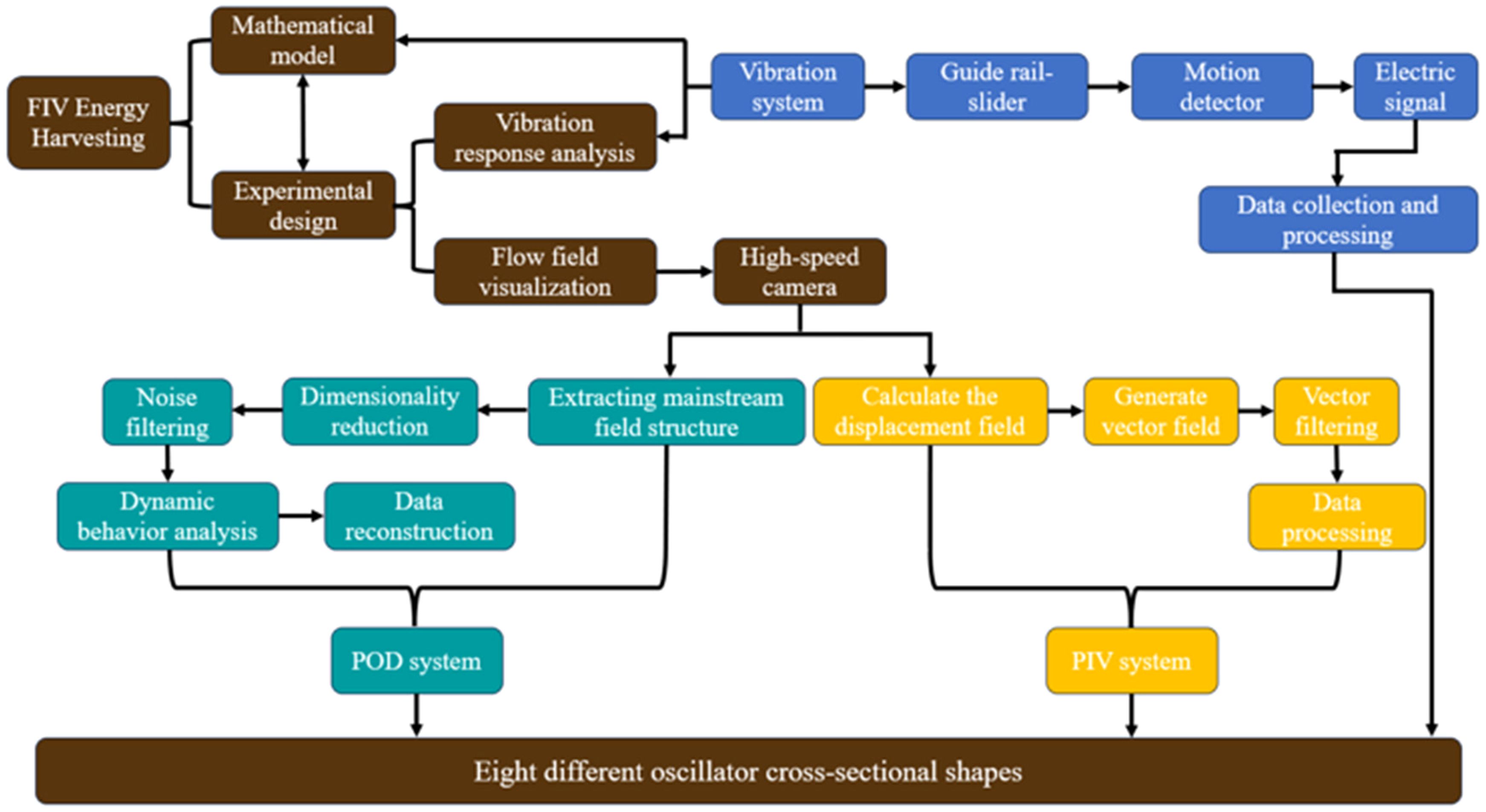
The optimization of oscillators for flow-induced vibration (FIV) power generation is often pursued through studies of oscillators with diverse cross-sectional shapes or by enhancing their energy conversion capabilities with symmetrically placed attachments (Lian et al., 2023). Despite the established advantages of oscillators with triangular and T-shaped cross-sections in improving energy capture efficiency (ECE), as demonstrated by theoretical analyses and experimental validations, it remains poorly understood whether the energy capture capability can be further enhanced by adding two symmetrically arranged rod attachments to various cross-sectional oscillators with high energy capture potential. The complexity of the flow field, which includes turbulence and changes in flow regimes, complicates the clear delineation of vibrational mechanisms for oscillators with different cross-sections. Therefore, significant exploration is still needed in this area. In this context, the vibration states and energy-harvesting characteristics of eight new oscillator shapes within the Reynolds number range of 5.041 × 10³ to 7.562 × 10⁴ are analyzed for the first time. Subsequently, the flow field near the oscillator is visualized by combining Particle Image Velocimetry (PIV) and Proper Orthogonal Decomposition (POD). Departing from conventional studies that primarily utilize theoretical or numerical simulation methods to investigate turbulence, this research adopts an experimental approach, as illustrated in Figure 1. In this study, a power generation device for FIV was designed with a particular focus on optimizing the shape of the oscillator. The aim is to demonstrate that adding symmetrically arranged attachments to oscillators is a key mechanism for enhancing the energy efficiency of FIV power generation devices. This research also addresses the lack of comparative experimental analyses on oscillators of various cross-sectional types with the addition of two rod attachments, as well as the absence of visual analyses in FIV energy capture experiments that clarify the interactions between the oscillator and the flow field. By optimizing the structure of oscillators and analyzing the vibration states, energy-harvesting characteristics, and flow fields, this study will contribute to the development of efficient energy conversion systems. Ultimately, these advancements have the potential to play a pivotal role in realizing the practical value of marine energy as a clean and renewable power source.
2 Mathematical model
FIV responses are elucidated through the classical mass-spring-damper oscillator model in this study. Specifically, the motion of the cylinder in the z-direction is accurately described by a second-order linear equation (Lin et al., 2009). The direction of the incoming flow is defined as the positive x-direction, while the vibration behavior of the vibrator primarily focuses on the state parameters in the z-direction. Consequently, the pulse of the vibrator can be represented by a second-order linear differential equation as follows:
To define the motion of the cylinder, a typical mass-spring-damper combined oscillator model is introduced in this research. Where z is the displacement perpendicular to the flow and cylinder axis; is the total mass of the oscillating system, including one-third of the spring-mass is the total damping coefficient; In this model, the fluid force is divided into a vortex component and an inviscid component, as described by Sun et al. (2016). The FIM conversion power of the oscillator (PFIM) is defined as:
represents the average period of oscillator oscillation. Combining Equations 1, 2 can get:
According to the research of Bernitsas et al (2008) , the simplified terms in Equation 2 can be simplified to get the following equation:
Therefore, the power associated with the swept area of the vibrator's cross-section can be determined for various cross-sectional shapes. Based on the Bernoulli Equation, the following expression can be derived:
The next step is to calculate the utilization efficiency of ocean current energy. Firstly, it is essential to reference the Betz Limit coefficient (16/27), which represents the maximum energy that a structure can extract from the fluid. On this basis, the ratio of the output energy of the VIV energy conversion system to the energy of the incoming flow is calculated. The equation can be expressed as:
This paper employs the snapshot Proper Orthogonal Decomposition (POD) method to discretize the original flow field. A set of N snapshots, obtained through experimental or simulation techniques, forms the discrete representation of the flow field. Each snapshot contains m discrete physical quantities, such as velocity, pressure, and temperature, within the spatial domain of the flow field. The equation can be expressed as:
The entirety of the space-time flow field information is denoted as:
where signifies the time-averaged flow field, while represents the time-varying pulsating flow field denoted as i = 1, 2, 3…, N. The POD method employed herein is centrally concerned with quantifying the pulsation within the flow field. This involves a decomposition process, segregating the pulsation amount into time-dependent coefficients and spatially dependent modes:
where, represents the temporal coefficient, and denotes the spatial mode. The construction of the original flow field matrix is delineated as:
Subsequently, the construction of the correlation matrix is undertaken as:
The matrix P in the provided equation is constituted by snapshots of the original flow field subtracted from the time-averaged flow field. Matrix C, with an order of N×N, characterizes the snapshot Proper Orthogonal Decomposition (POD) method. Unlike the original POD method, which produces an m×m order matrix, the snapshot POD method converts the high-order m-dimensional matrix into an N-dimensional matrix. This shift in dimensionality improves computational efficiency while maintaining the capability to capture the essential dynamics of the flow field, representing a significant enhancement in the analytical approach. Given the symmetry of matrix C, it inherently possesses non-negative eigenvalues. The solution for the correlation matrix C involves determining its eigenvalues denoted by:
3 Experimental setup
3.1 Oscillator types
FIV power generation is specifically designed to harness energy from low-velocity seabed flow environments. Research aims to modify oscillators to enhance the efficiency of energy harvesters continues to be an ongoing endeavor. Hu et al (2018) have conducted focused investigations into the efficiency of an energy harvester equipped with a circular cylinder, to which various rods (circular, triangular, and square) were attached at differing positions. Their findings advocate for the employment of a triangular rod (10% D) positioned at a 60-degree angle, which was identified as optimal for improving the device's efficiency. The semicircular rod-shaped attachment added to the oscillator in this experiment adopts a similar configuration. In this study, two semicircular rods, positioned at a 60-degree angle to facilitate mounting on curved surfaces (10% D), were utilized. The experimental study was conducted using an acrylic oscillator, which was compared to an oscillator fitted with the two rods. The characteristic dimension D of the oscillator was 0.09 m, and the length L was 0.46 m. Figure 2A presents a cross-sectional view of all oscillator types tested in the experiment, while Figure 2B provides an actual image of the tested oscillators. The characteristic scale of the oscillators is denoted as D, elucidating the diverse morphologies encompassed within the study: Circular, Cir-Hex, Circular-Trapezoid I, Circular-Trapezoid II, Cir-T, and Circular-Triangle. The experimental platform is shown in Figure 2C.
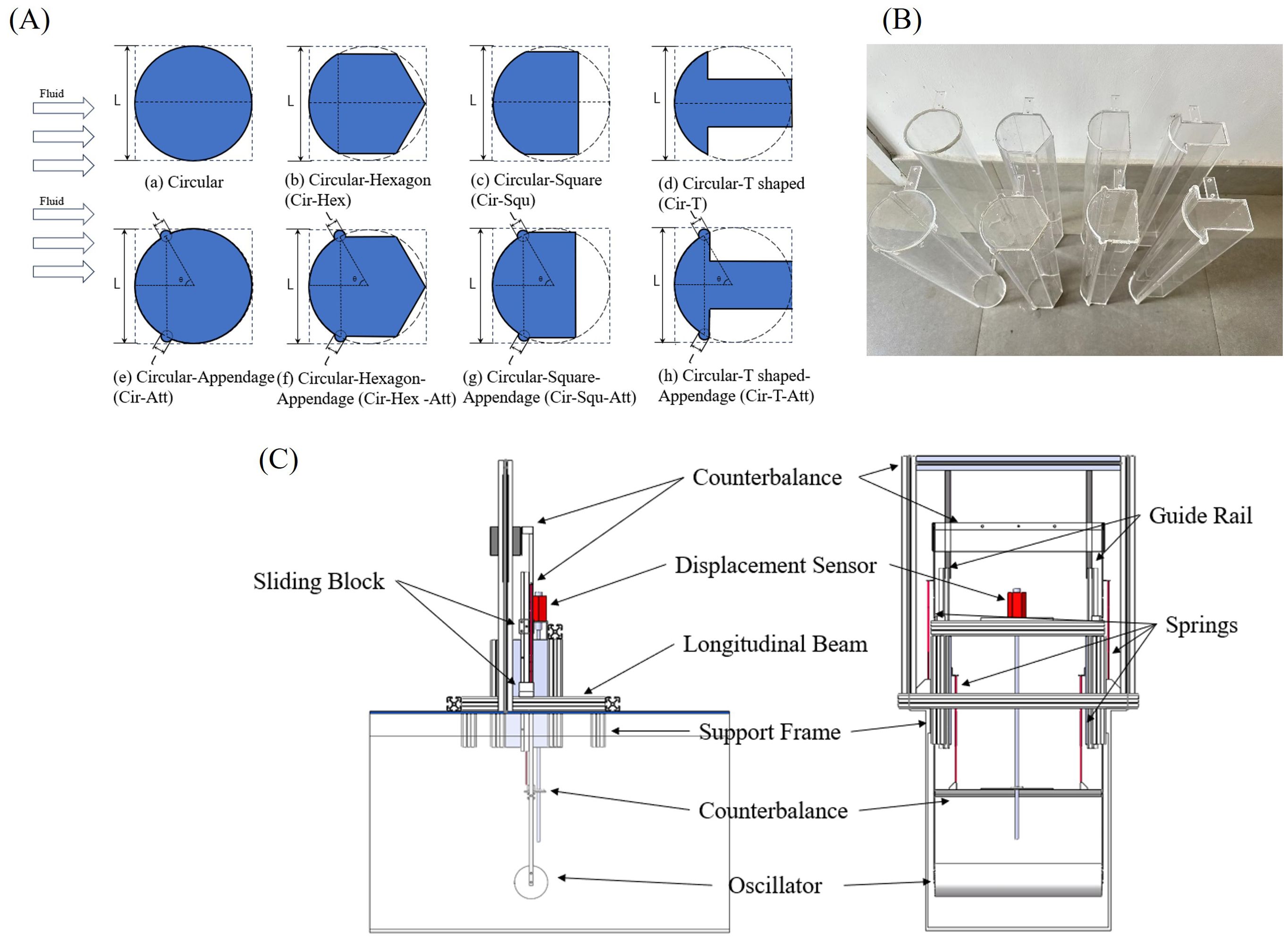
Figure 2. Oscillators and various components of experimental equipment: (A) cross-sectional shape; (B) oscillator physical picture; (C) schematic diagram of the experimental model.
3.2 Specification of experiment
The recirculating water tank employed in the experiment is at Zhejiang Ocean University, as shown in Figure 3. The experiment will be carried out in the wave-current flume. The water tank measures 20 meters in length, 0.6 meters in width, and 0.6 meters in height, with a flow-rate range from 0 L/s to 100 L/s. The flume can physically generate constant current (U=0.05 m/s~0.75 m/s). The basic parameters are shown in Table 1.
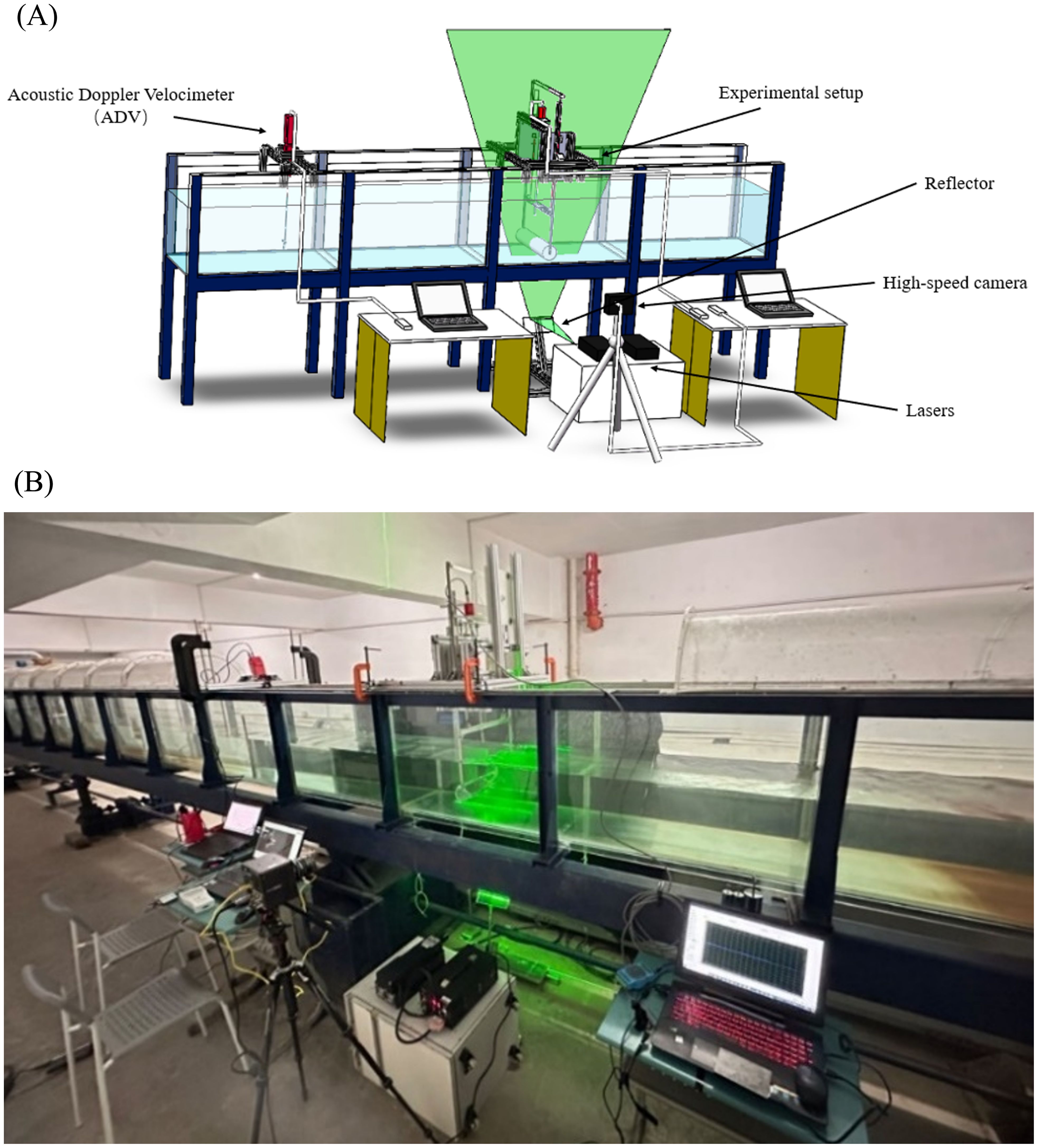
Figure 3. The experimental installation: (A) the design model of the experimental installation; (B) the actual model of the experimental installation.
This study aims to investigate the flow field characteristics around a vertically moving two-dimensional rigid oscillator. The oscillator is mounted on an aluminum support frame and is connected by four springs to a frame fixed to the flume, as illustrated in Figure 4. The distance between the oscillator and the boundaries (flume bottom or water surface) is 0.21 m. Previous research (Hsieh et al., 2017) has substantiated that the characteristics of Vortex-Induced Vibration (VIV) response and the associated flow field remain minimally influenced by the presence of a boundary when the gap-to-diameter ratio (g/D) surpasses 1.5. In this context, the maximum vibration amplitude, recorded at approximately 0.91D, corresponds to a g/D value of 2.44. Given this substantial ratio, it can be inferred that the influence of the boundary on the observed results is expected to be negligible. The total weight of the vibrating system, which includes the circular cylinder and the aluminum frame, is 0.998 kg. resulting in an equivalent mass ratio (m*) of 1.175.
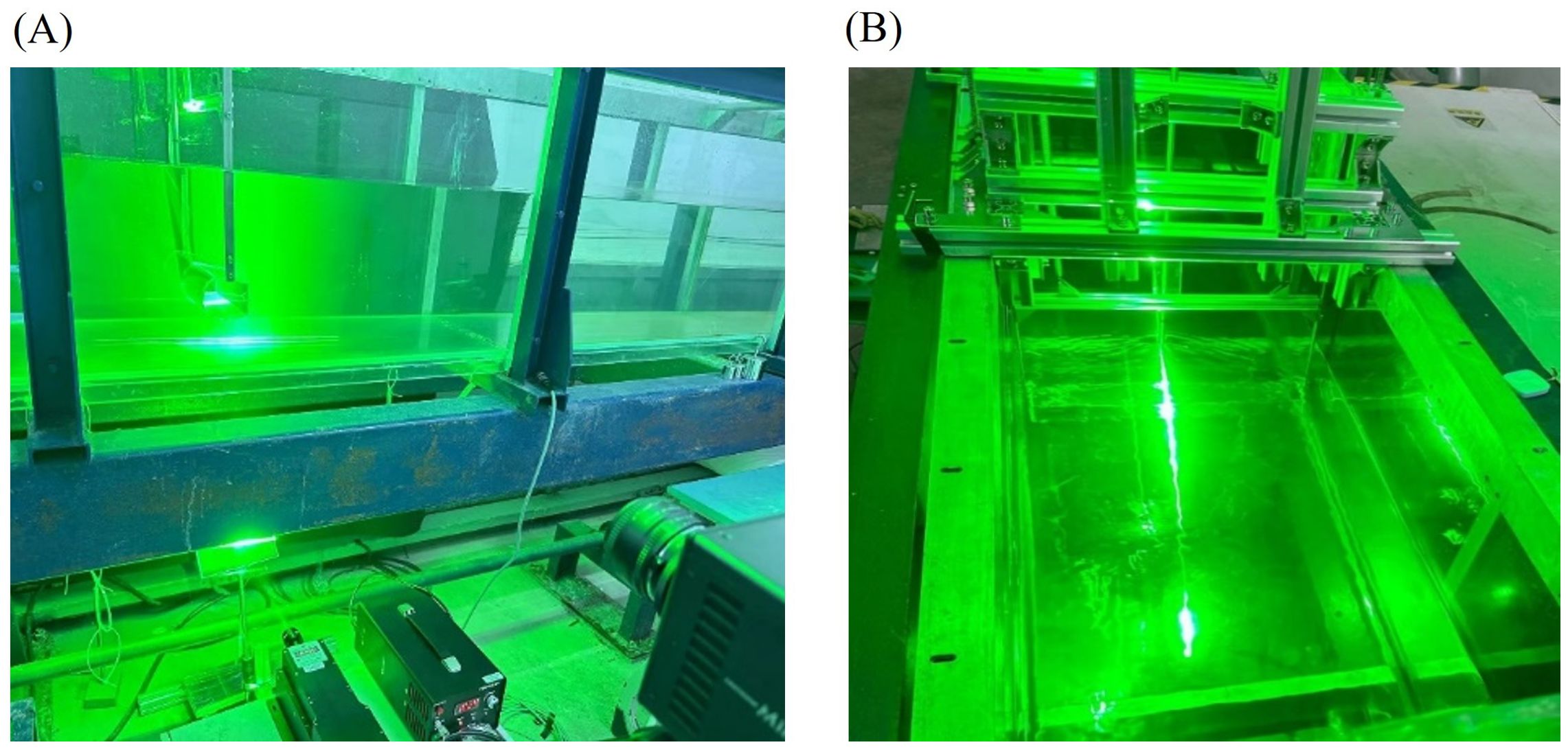
Figure 4. High-speed cameras and laser effects in water in PIV systems: (A) the laser device and the high-speed camera; (B) the laser beam in water.
In the experimental framework, the veritable flow velocity is quantified utilizing the Acoustic Doppler Velocimeter (ADV), complemented by a portable flow meter to corroborate the precision of the measured flow rate. This concurrent deployment of instrumentation ensures the fidelity and accuracy of the acquired flow velocity and rate data, thereby underpinning the robustness of the experimental methodology. The PIV measuring system consists of a 10 W air-cooled laser with a wavelength of 532 nm, which serves as the light source, and a high-speed camera (FASTCAM Mini UX50). The laser beam, emitted from the light source, is reflected by a mirror, creating a laser light fan with a 60-degree expansion angle that is projected upward into the water through the base of the glass flume. The experiment employs polyhedral non-spherical particles with a diameter of 5 µm and a density of 1.03 g/cc as seeding particles. Applying Stoke's law, the settling velocity of these particles is estimated to be less than 0.01 cm/s, markedly smaller than the free stream velocity. This configuration ensures precise particle tracking for accurate flow field measurements. The working conditions of the experimental test are shown in Table 2.
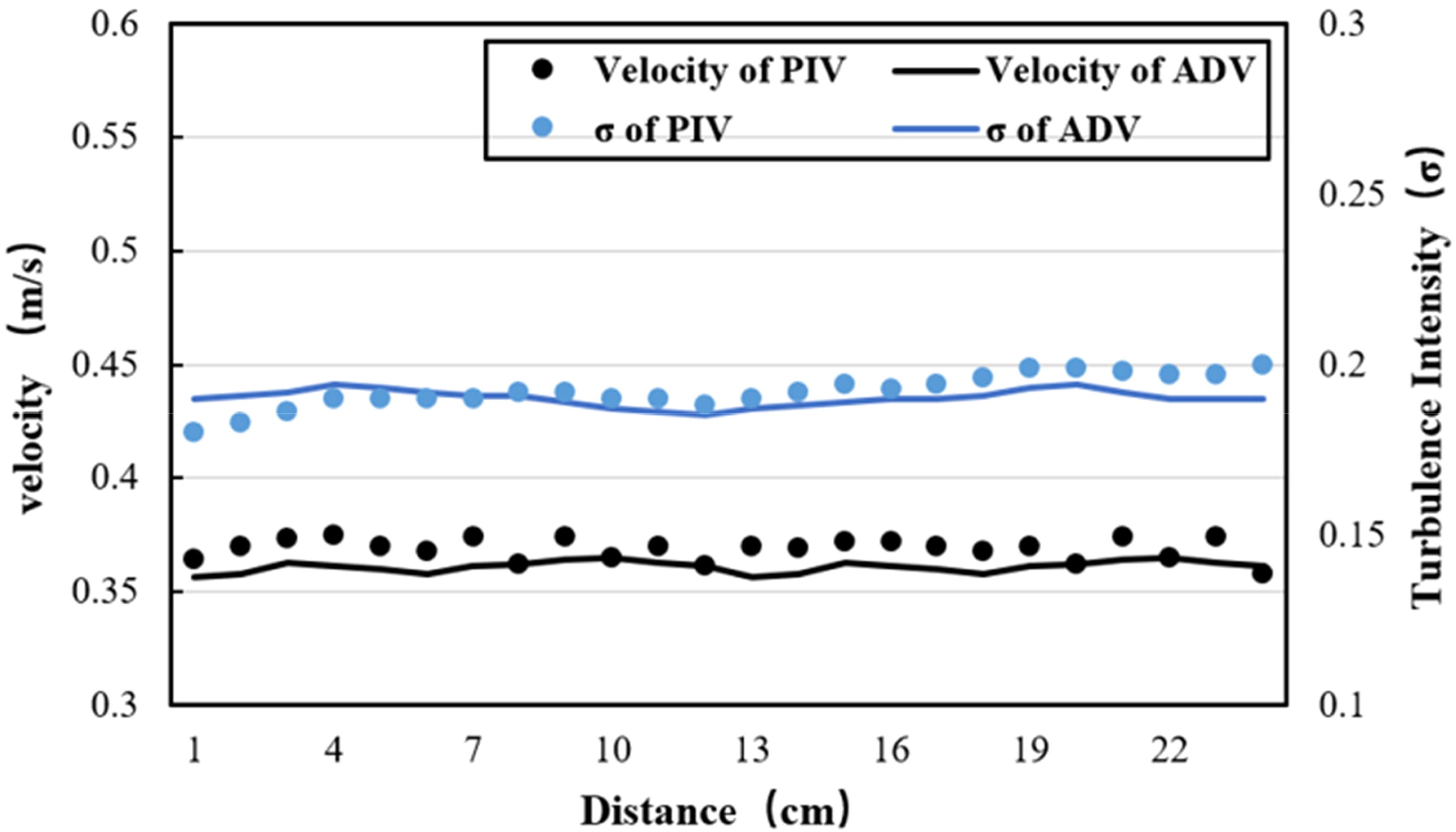
The findings from the decay tests, which include both air decay testing (conducted in the absence of water) and decay testing performed in quiescent water conditions, reveal a damping coefficient range of 1.5% to 2.5%.To validate the accuracy of the velocity field and turbulence characteristics acquired through PIV, a comparative analysis was conducted with data obtained from a Doppler Velocity Profiler (DVP). Figure 5 illustrates the congruence between the results derived from PIV and DVP measurements. Notably, the maximum disparity for mean velocity fields is less than 3.93%, with turbulence intensity (σ) discrepancies falling within 5.26%. These findings attest to the reliability and consistency of the PIV methodology in capturing velocity profiles and turbulence characteristics, thereby affirming its suitability for the precise characterization of fluid flow phenomena. The mathematical model for σ is elucidated in Equation 13.
4 Results and discussion
Vortex shedding is a prominent characteristic observed in the wake of the oscillator. When fluid flows past a circular cylinder, distinct inward spiraling motions develop within the upper and lower shear layers, originating at the separation points on the cylinder's surface. These motions effectively draw adjacent irrotational fluid into a rotational state, resulting in the formation of systematic shedding vortices. Employing flow visualization proves instrumental in illustrating analogous flow phenomena around a novel oscillator (Kim et al., 2021; Adrian et al., 2000). To understand the nuanced influence of various cross-sectional oscillators on flow dynamics, it is essential to visualize the downstream flow patterns generated by the oscillators. In this section, we will analyze the data from the experiment. Based on the results, we will explain the effects of different cross-sectional oscillators on flow-induced vibrations (FIV), considering both the effects of flow velocity and spring stiffness in two scenarios: with attachments and without attachments. To ensure a uniform and unbiased comparison of experimental outcomes for oscillators with diverse cross-sections, we have chosen to calculate the reduced velocity based on the natural frequencies of these oscillators in air (). The added mass coefficient () for a circular cross-section oscillator is conventionally treated as 1. Conversely, for oscillators with non-circular cross-sections, determining both the and the is highly intricate, leading to diverse opinions among researchers. Analyzing the added mass effect in noncircular cross-section oscillators remains challenging. To ensure a standardized comparison of experimental results across distinct cylinders, we have opted to calculate the reduced velocity { )} and frequency ratio (f* ) based on the . This methodological choice allows for a consistent and impartial evaluation of dynamic responses across various cylinder types under equivalent conditions. This methodological approach (Lian et al., 2023) ensures that the comparison is conducted under consistent conditions, thereby mitigating any potential confounding factors associated with variations in cross-sectional geometry.
4.1 Experimental results analysis of circular and Cir-Att
Given the bottom-to-top irradiation of the laser, the upper region of the oscillator exhibits significant interference in its display, primarily due to laser scattering within the oscillator. As a result, this upper portion is excluded from certain analyses. Figure 6A showcases downstream flow patterns of Circular and Cir-Att. Regular vortex shedding is observed through flow visualization over multiple periods, noting distinct sizes of vortices from the upper and lower shear layers of the oscillators. Figure 6A provides a comprehensive depiction of the flow field characteristics surrounding the fixed oscillator operating under the condition of Ur = 5.5. The original visual representations are presented in (a) and (b), offering an unfiltered view of the flow field. Transitioning to a quantitative analysis, (c) and (d) present velocity vector diagrams, providing a detailed insight into the fluid dynamics. Particularly notable is the depiction in (e) and (f), where velocity vector maps have undergone meticulous filtering, resulting in heightened clarity and accentuation of discernible features. The analysis depicted in (c) offers a comprehensive insight into the morphology and thickness of the boundary layer, pinpointing the location of boundary layer separation, the presence of alternating deflated tail vortices, and the gradual attenuation of the trailing vortex. A comparative examination of an oscillator featuring a symmetrically arranged semicircular appendage, as illustrated in (d), reveals significant distinctions. Specifically, a reduction in boundary layer thickness is observed at the front end of the appendage. Meanwhile, a substantial decrease in flow velocity at the rear end of the appendage induces the formation of an anticlockwise backflow, resulting in the creation of a distinct vortex. The introduction of a semicircular attachment to the Circular oscillator induces a discernible shift in the position of the shear layer, relocating it downward by 0.17 D. This alteration results in a noteworthy adjustment to the original position of vortex discharge, with the vortex separation point advancing to the rear position coinciding with the location of the attachment. A distinctive zone of unstable flow field emerges behind the oscillator, contributing to heightened instability in the shear layer.
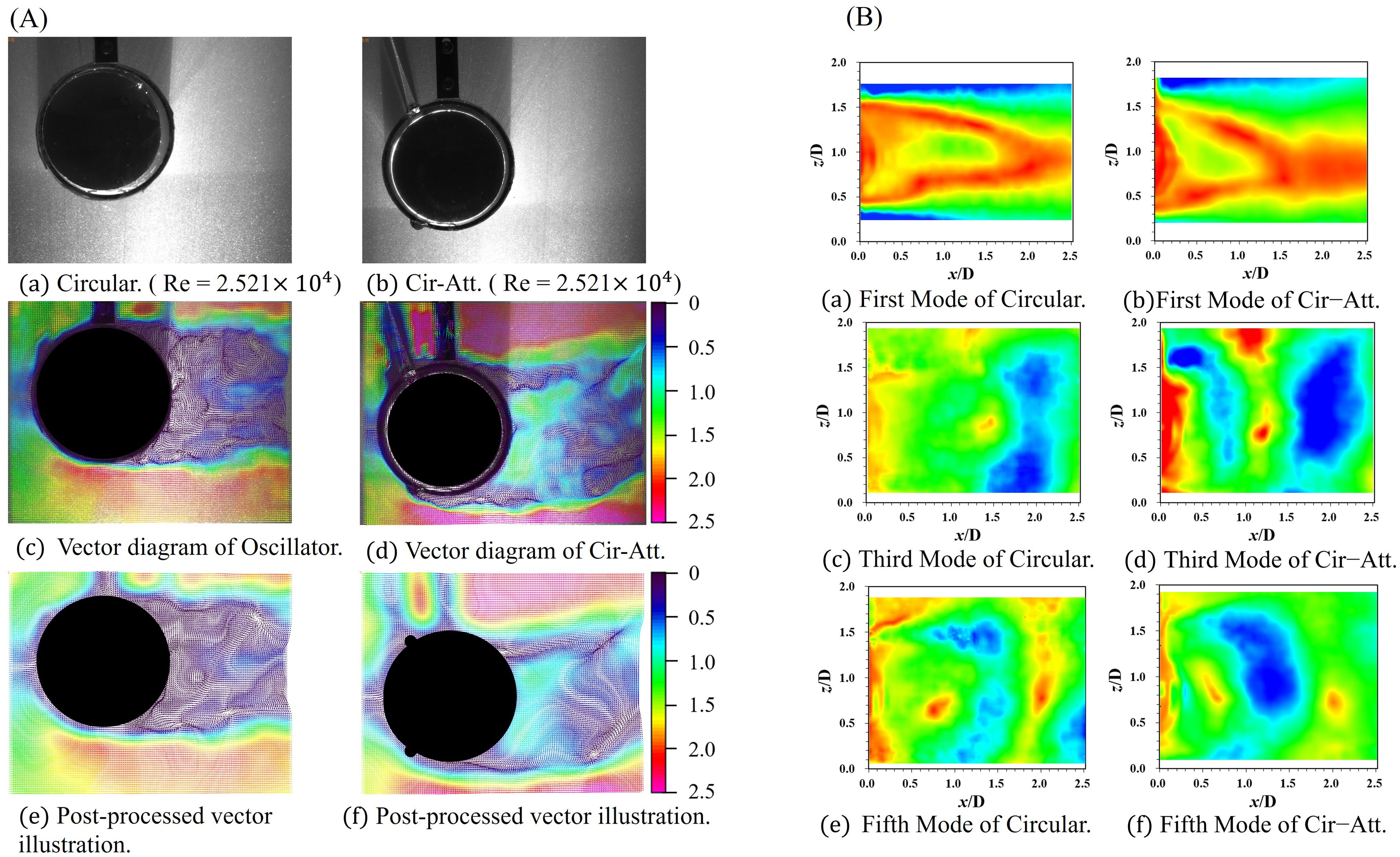
Figure 6. The vector illustration and the POD flow field reconstruction results of the Circular cross-section oscillator and the Cir-Att: (A) the vector illustration of PIV; (B) the POD flow field reconstruction results.
The evolution of the tail vector field is depicted for both oscillators across the range from 0.3 T to 1.2 T, as shown in Figure 7A. In these figures, The "Q" stands for "Quantity" and the numbers (1, 2, etc.) denote the sequence in which the vortices are shed from a structure at different time points during the flow. Q1 represents the position or characteristics of the first vortex that detaches from the structure. Q2 represents the second instance of vortex shedding, following the first, and indicates the position of the second vortex, and so on. A general trend emerges, highlighting the greater evanescence of the tail vortex associated with the Circular cross-section oscillator compared to the tail vortex of the Cir-Att. The author posits that two primary factors contribute to observed phenomena. The overall performance of the oscillator is not uniformly improved by the addition of semicircular appendages; however, the tail vortex track becomes more diffuse when compared to the oscillator without a semicircular appendage. The second key consideration pertains to the impact of adding a semicircular appendage on the incoming flow. The semicircular appendage hinders a portion of the incoming flow, redirecting it along the boundary layer outside a defined area of the flow field. This redirection creates an additional pressure field, changing the initial direction of vortex leakage compared to scenarios without the semicircular appendage. Consequently, there is a modification in the angle of vortex leakage, causing the trajectory of the trailing vortex in the oscillator with the added semicircular appendage to converge more towards the centerline when compared to the trajectory in the oscillator without the semicircular appendage.
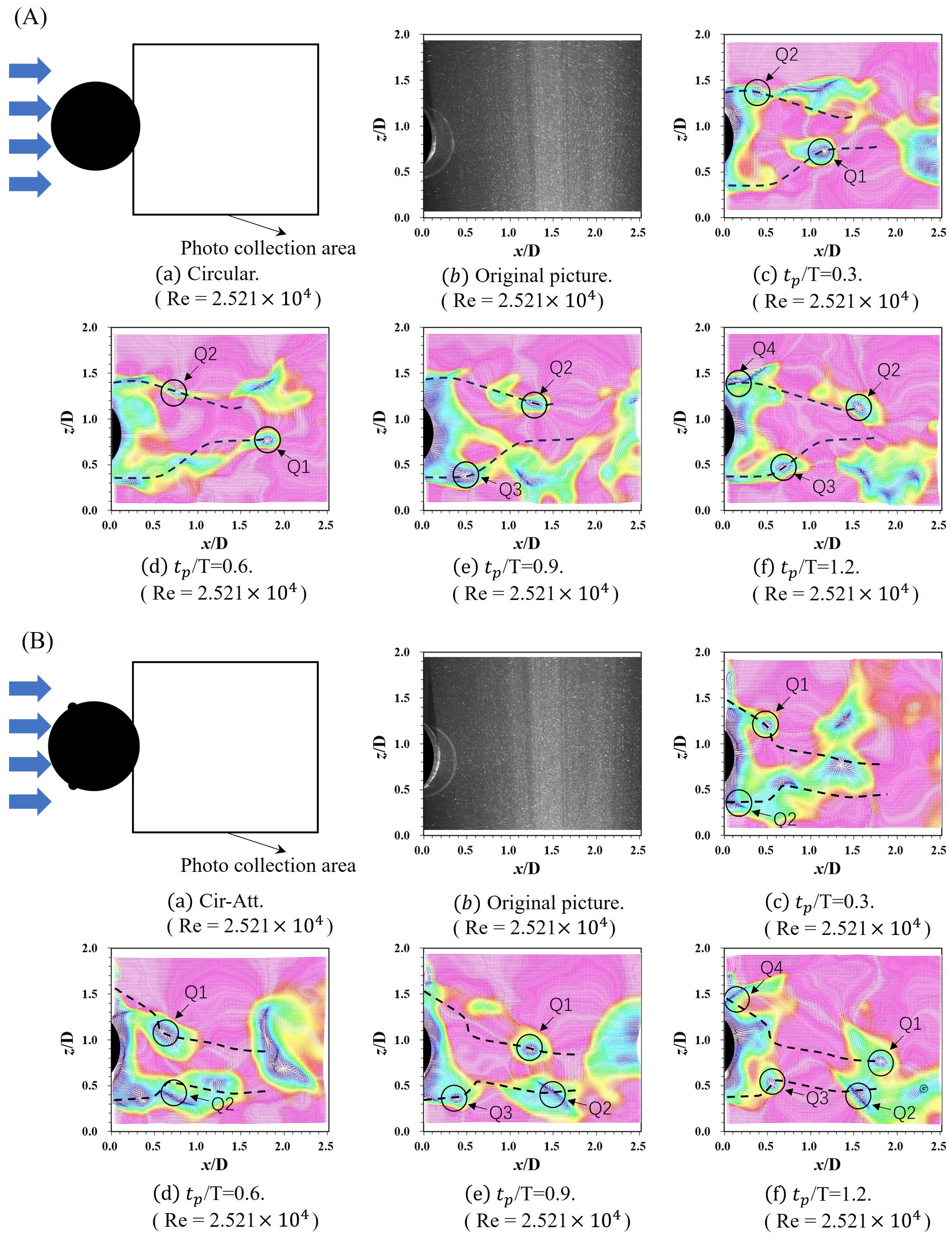
Figure 7. The vector diagram of the Circular cross-section oscillator and the Cir-Att at distinct moments within a single cycle: (A) the vector illustration of Circular; (B) the vector illustration of Cir-Att.
A comparative analysis involving the oscillator with a semicircular attachment reveals a conspicuous change in the vortex discharge angle. Figure 7B illustrates the dynamic evolution of the tail vortex in the Cir-Att at four distinct temporal instances: 0.3T, 0.6T, 0.9T, and 1.2 T. The trajectory of the tail vortex in the oscillator with a semicircular attachment is more tightly concentrated toward the centerline compared to its counterpart without the attachment. Notably, there is a significant increase in the frequency of vortex release for the oscillator with semicircular appendages. The wake diagram, following the application of Proper Orthogonal Decomposition (POD), is presented at the end of this section in Figure 7: (a) the first mode of the circular cross-section, (b) the first mode of the oscillator with add-ons, (c) the third mode of the circular cross-section, (d) the third mode of the oscillator with add-ons, (e) the fifth mode of the circular cross-section, and (f) the fifth mode of the oscillator with add-ons. Comparative analysis of mode one reveals that the introduction of a semi-circular attachment results in a more dispersed vector field in the wake of the oscillator. Further scrutiny in mode two demonstrates a significant increase in the number of vortex pairs per unit distance. The author attributes this effect to the combined influence of two factors: firstly, the arrangement of the semicircular appendage widens the flow field in the tail, leading to a relative reduction in flow velocity; secondly, the appendage arrangement causes the tail vortices to converge more towards the centerline.
Both the circular cross-section oscillator and the Cir-Att exhibit the soft galloping (SG) trend; however, the galloping branch is not fully developed. This observation suggests a potential limitation in the velocity condition, indicating that the amplitude of the vortex-induced vibration (VIV) branch may not reach a level sufficient to induce galloping oscillations. The introduction of a semicircular appendage to the oscillator induces a conspicuous alteration in the VIV branch, transitioning from to . Under the premise that , our investigation reveals a distinct maximum amplitude ratio within the defined range of test conditions.
The circular cross-section oscillator and the Cir-Att exhibit a progression from soft galloping to oscillation within the VIV initial branches and VIV-Galloping transition branches, as the reduced velocity increases. In the VIV initial branches, at Ur = 4.7, Cir-T-Att initiates vibration, with both A* and f* showing a rising trend, albeit with relatively small values. As Ur increases, the Circular cross-section oscillator sees a rapid jump in A* to about 1.63, and f* stabilizes around 0.84. Similarly, for the Cir-Att, A* jumps to about 1.67, with f* stabilizing around 0.81, and vortex shedding frequency locks onto the oscillation frequency of the oscillator. As Ur experiences further increments, A* demonstrates a persistent and stable trend. Concurrently, f* exhibits a subtle decreasing pattern, signifying the transition into the VIV-Galloping branches.
The oscillation in the VIV branch stage is primarily caused by the alternating lift force generated by shedding vortices. However, changes in the cross-sectional shape of the oscillator significantly alter the position and direction of the shed vortex, thereby modifying the alternating lift force experienced by the oscillator. In a general sense, the addition of a semicircular appendage to a Circular cross-section oscillator enhances vibration A*, with a minor influence on frequency. Notably, it reduces Ur required for f* to reach its peak.
4.2 Experimental results analysis of Cir-Hex and Cir-Hex-Att
The width of the flow field at the tail of the oscillator is slightly reduced compared to that of the circular cross-section oscillator, as illustrated in Figure 8A. Detailed observations in (c) and (d) highlight the significant shift in the position of the shear layer caused by the addition of a semicircular appendage to the oscillator. Notably, the vortex separation point moves to a position at the rear that corresponds to the location of the appendage. This change results in a distinct interval characterized by an unstable flow field, which generates an elongated vortex. The presence of this elongated vortex creates a cascade effect, influencing the overall vortex structure and consequently leading to noticeable changes in vibration frequency and amplitude.
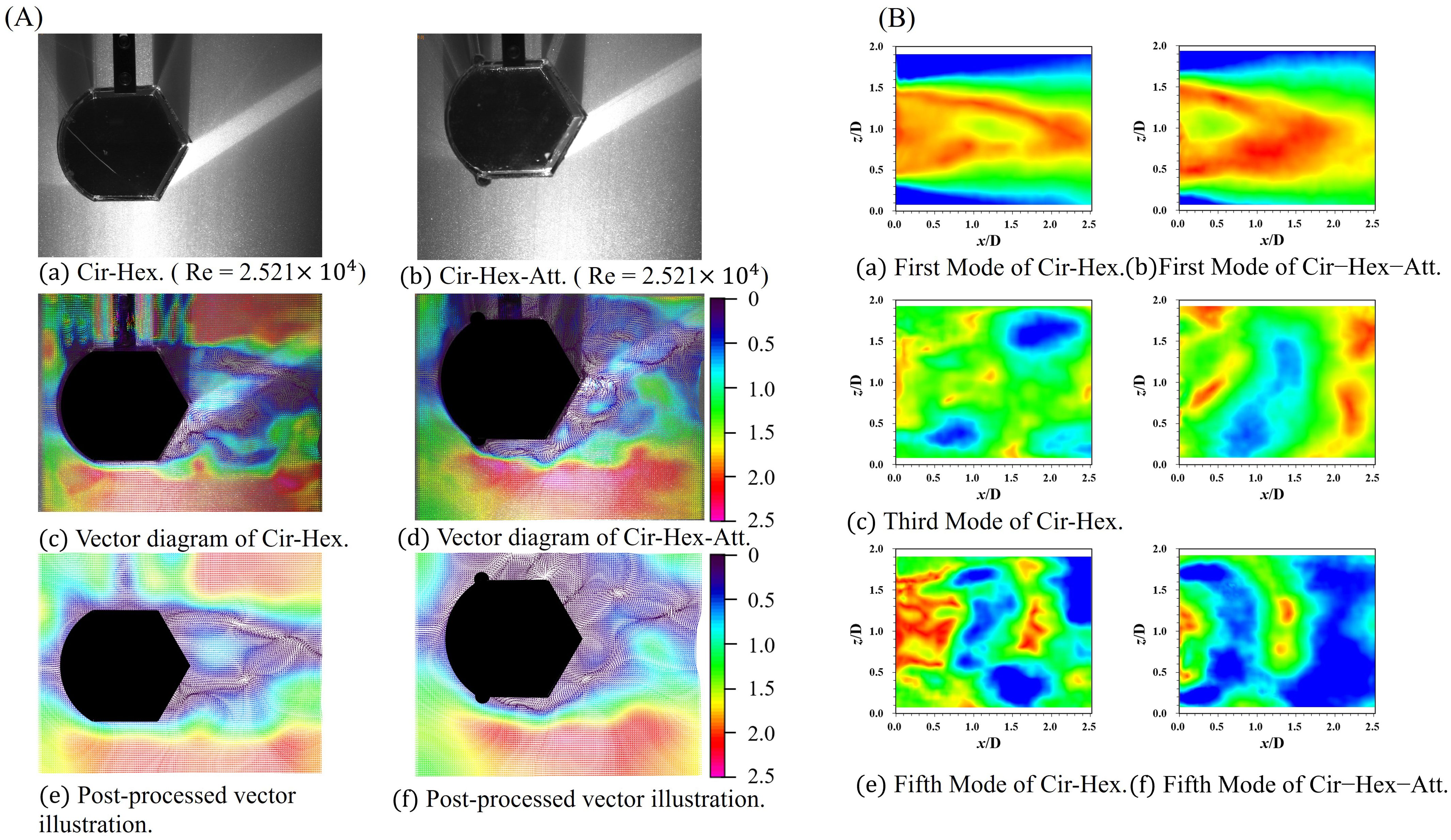
Figure 8. The vector illustration and the POD flow field reconstruction results of the Cir-Hex and the Cir-Hex-Att: (A) the vector illustration of PIV; (B) the POD flow field reconstruction results.
The flow field in the tail of the oscillator with added appendages is characterized by increased turbulence. Insight into the dissimilarity in the frequency of the unloading vortex cycle is provided by the POD plots, as portrayed in Figure 8B. Notably, the oscillator with the addition of the semicircular appendage exhibits a discernibly higher frequency of unloading vortex in comparison to the oscillator without the appendage. A focused analysis of mode 2 reveals that the tail vortex release in the oscillator with the semicircular appendage aligns more closely with the characteristics of a P+S vortex release pattern. The dynamic evolution of the tail vector field for both oscillators, across temporal instances from 0.3 T to 1.2 T, is depicted in Figures 9A, B. A general trend emerges, indicating that the tail vortices exhibit greater divergence for the Cir-Hex compared to the Cir-Hex-Att.
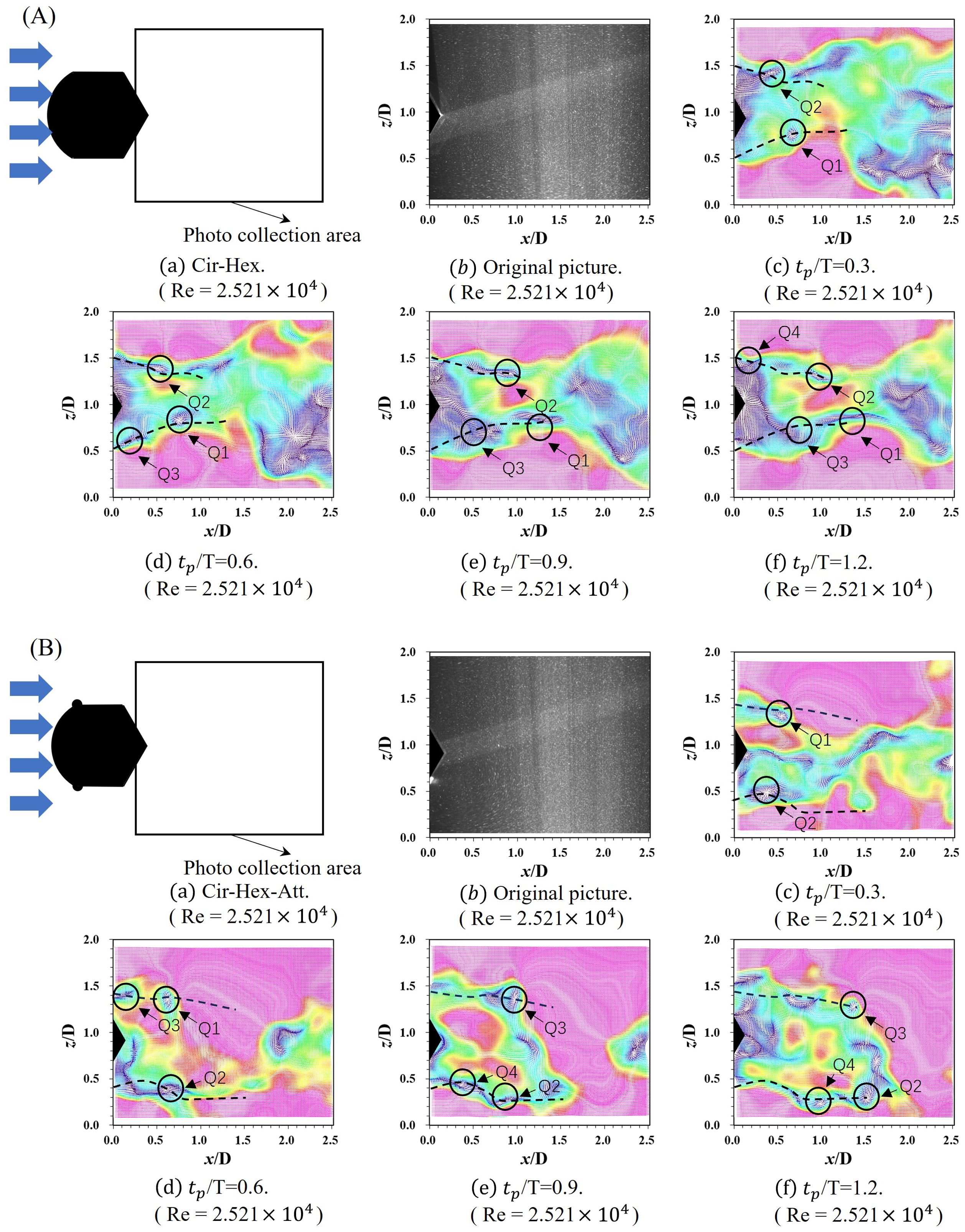
Figure 9. The vector diagram of the Cir-Hex and the Cir-Hex-Att at distinct moments within a single cycle: (A) the vector illustration of Cir-Hex; (B) the vector illustration of Cir-Hex-Att.
The Cir-Hex and the Cir-Hex-Att counterpart exhibit a SG trend as Ur increases,. The A* of the Cir-Hex-Att shows continuous growth. Concurrently, there is a subtle and gradual increase in the frequency ratio (f*) of the oscillator's response, reflecting the evolving dynamics of the system in response to varying flow conditions. The trend tends to stabilize at around 0.8, indicating the transition of oscillation into VIV branches and VIV-Galloping transition branches with the increase of Ur. However, due to limitations in Ur, the galloping branches do not fully develop within the tested conditions, with the maximum A* reaching 0.29 at Ur = 15. A* of the Cir-Hex-Att exhibits continuous growth and this growth persists even after Ur reaches 12.8. Concurrently, there is a subtle and gradual increase in f* of the oscillator's response. This behavior indicates the transition of oscillation into VIV branches and VIV-Galloping transition branches with the increase of Ur. Within the tested conditions, the Cir-Hex-Att attains a maximum A* of 0.37 at Ur = 15.
4.3 Experimental results analysis of Cir-Squ and Cir-Squ-Att
A visual representation revealing a reduced width of the flow field at the tail of the oscillator is provided in Figure 10A. Further examination in (c) and (d) accentuates the distinct shift in the shear layer position induced by the addition of a semicircular appendage to the oscillator. The results of the POD analysis are shown in Figure 10B. The vortex shedding frequencies of Cir-Squ and Cir-Squ-Att are similar, with the latter being slightly higher than the former.
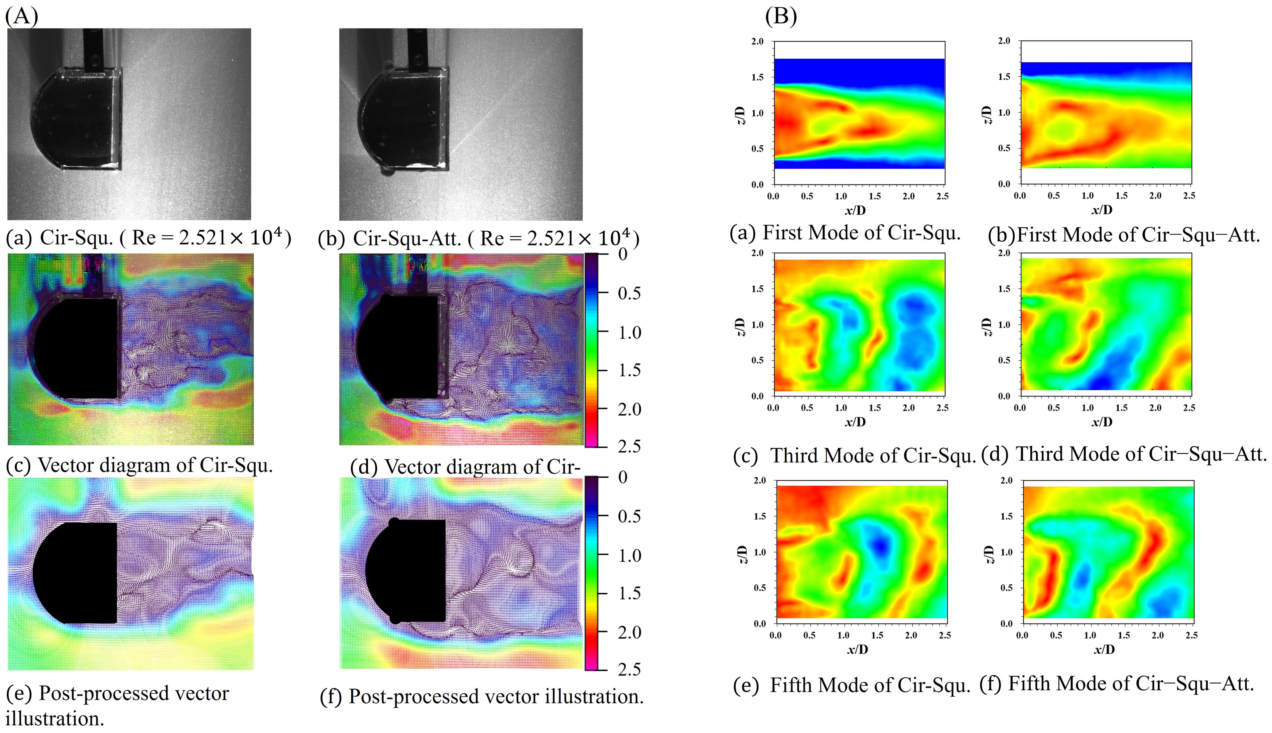
Figure 10. The vector illustration and the POD flow field reconstruction results of the Cir-Squ and the Cir-Squ-Att: (A) the vector illustration of PIV; (B) the POD flow field reconstruction results.
Remarkably, the vortex separation point advances towards the rear position corresponding to the appendage's location, as shown in Figure 11. This configuration gives rise to a unique interval characterized by an unstable flow field, resulting in the formation of an elongated vortex. The presence of this elongated vortex introduces a cascade effect, influencing the overall vortex structure and, consequently, leading to discernible changes in vibration frequency and amplitude. Both the Cir-Squ and the Cir-Squ-Att manifest SG; nonetheless, the complete realization of the galloping branch remains elusive. This observation implies a probable limitation in Ur. The introduction of a semicircular appendage to the oscillator precipitates a noticeable alteration in the VIV branch, shifting from to . Under the premise that , this investigation unravels a distinctive maximum amplitude ratio within the stipulated range of test conditions. This investigation aims to decipher the intricate dynamics governing the transition between VIV and galloping branches, offering valuable insights into the behavior of oscillators under diverse velocity conditions. The oscillatory behaviors of the Cir-Squ and the Cir-Squ-Att share a commonality in their overall trends. Both oscillators exhibit the SG trend, where A* increases continuously with the increase in Ur from 5.0 to 15.00. In terms of f*, the Cir-Squ sees an initial increase to 0.84, followed by stabilization at about 0.82. Similarly, the Cir-Squ-Att experiences an initial rise in f* to 0.82, followed by stabilization at 0.81.
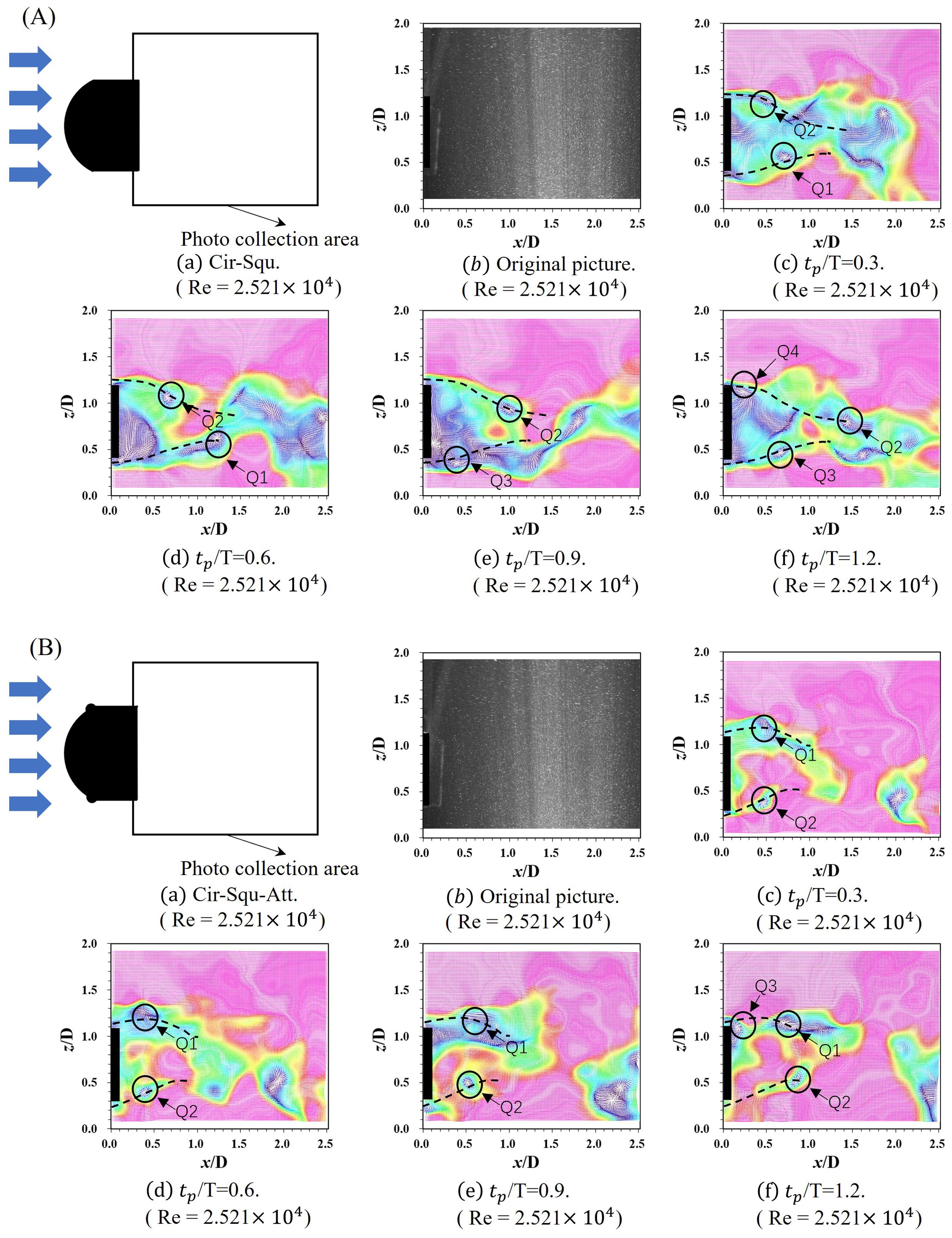
Figure 11. The vector diagram of the Cir-Squ and the Cir-Squ-Att at distinct moments within a single cycle: (A) the vector illustration of Cir-Squ; (B) the vector illustration of Cir-Squ-Att.
4.4 Experimental results analysis of Cir-T and Cir-T-Att
The two distinctive cross-section types exhibit unique characteristics regarding the flow field. Specifically, the Cir-T generates a minor vortex cycle at point A in isolation, which subsequently merges with the unloading vortex of the overarching structure as it moves toward the structure's tail. Importantly, the addition of semicircular attachments leads to an increase in the width of the local vortex release.
Where a notable observatio is the heightened frequency of the unloading vortex, as shown in Figure 12. This phenomenon can be attributed to the asynchronous nature between the local unloading vortex and the overall unloading vortex of the structure. The oscillation in the vortex-induced vibration (VIV) branch stage is attributed to the alternating lift generated by shedding vortices. The unique cross-sectional shape of the oscillator significantly alters the position of vortex shedding, directing it closer to the center. This fundamental modification affects the forces experienced by the oscillator during alternating lift. Notably, the addition of a semicircular appendage to the Cir-T is found to enhance A* while concurrently reducing f*. The Cir-T and the Cir-T-Att undergo a sequential evolution from soft galloping to oscillation across the VIV initial branches. VIV-Galloping transition branches and Galloping branches as Ur increases. In the VIV initial branches, at Ur = 3.4, the oscillator initiates vibration, with both A* and f* showing an ascending trend. As Ur increases, the Cir-T experiences a rapid surge in A* to approximately 1.67, while f* stabilizes around 0.76. Similarly, for the Cir-T-Att, A* jumps to about 1.71, with f* stabilizing around 0.73. Further increments in Ur result in continuous A* growth, while f* exhibits a slightly decreasing trend, marking the transition into the VIV-Galloping branches.
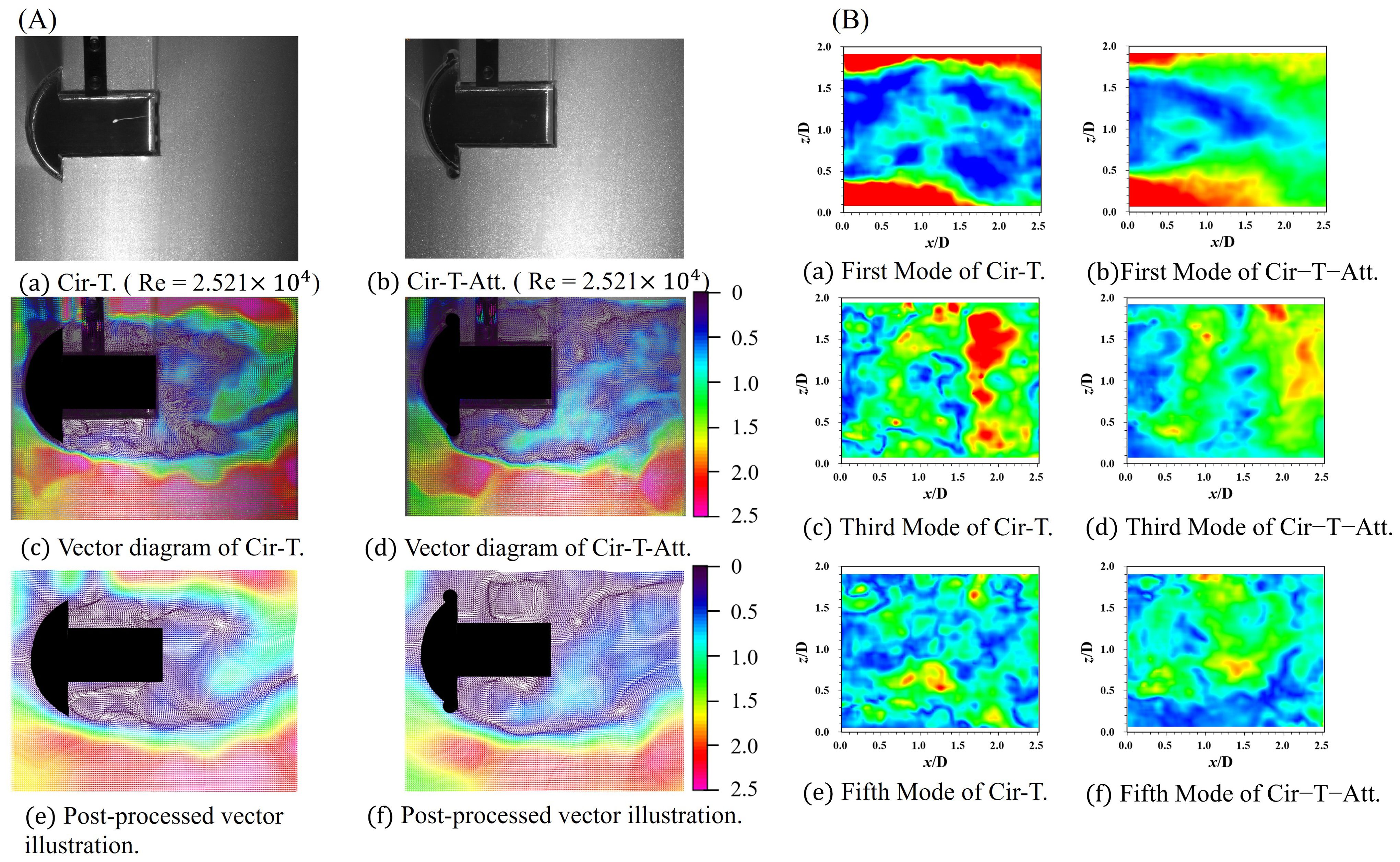
Figure 12. The vector illustration and the POD flow field reconstruction results of the Cir-T and the Cir-T-Att: (A) the vector illustration of PIV; (B) the POD flow field reconstruction results.
A noteworthy phenomenon emerges from the conducted investigation. Examining Figure 13. reveals that the T-shaped cross-section oscillator exhibits distinctive upper and lower vortex leakage pairs, akin to the 2S vortex leakage type at its protruding section. The introduction of a semicircular appendage introduces a reduction in vorticity intensity; nevertheless, comparable phenomena endure. This persistence implies that the addition of a semicircular appendage alters the flow dynamics of the T-shaped cross-section oscillator, leading to a modification in the vorticity patterns, despite the attenuation in vorticity intensity.
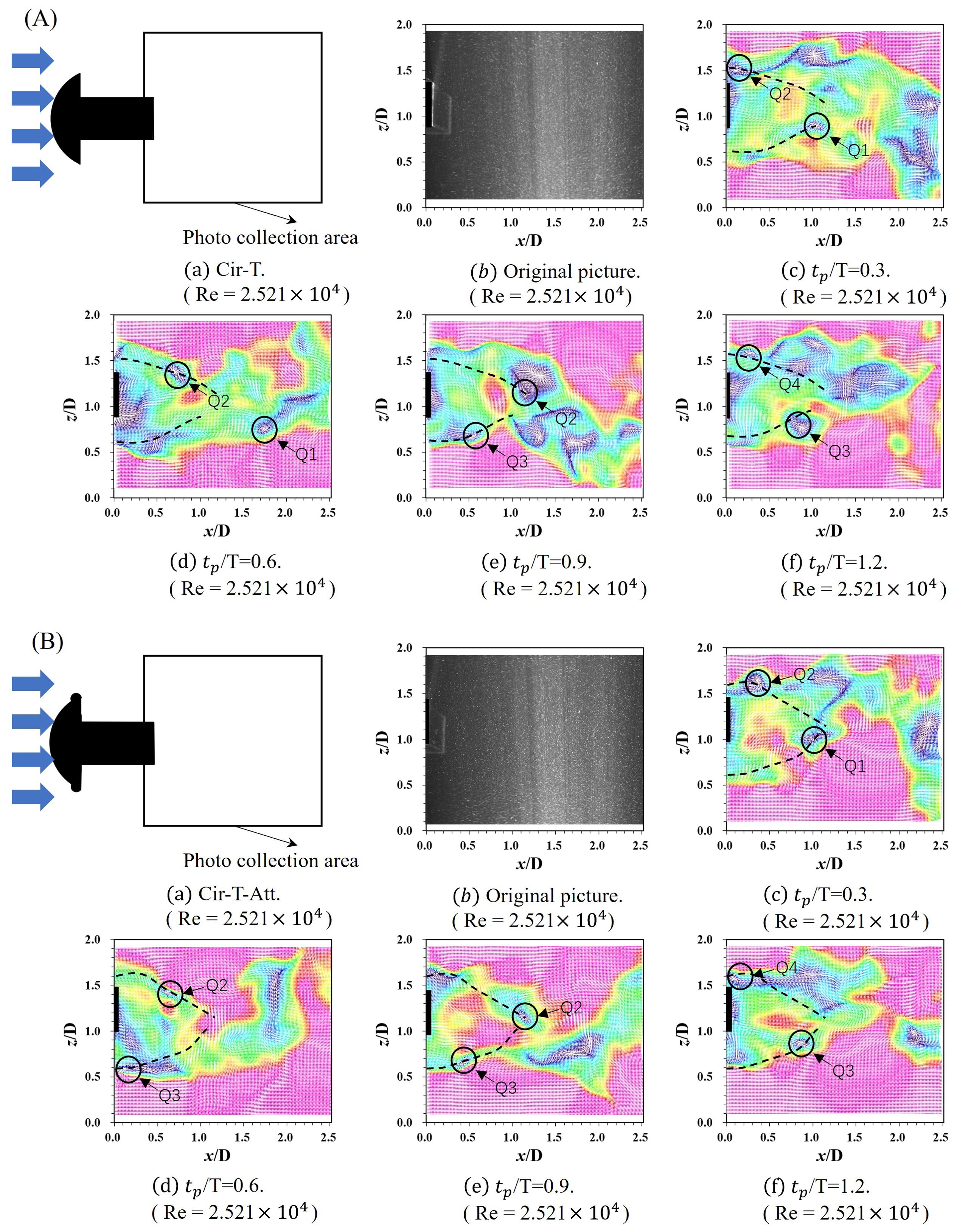
Figure 13. The vector diagram of the Cir-T and the Cir-T-Att at distinct moments within a single cycle: (A) the vector illustration of Cir-T; (B) the vector illustration of Cir-T-Att.
4.5 Comparison of oscillation intensity and ECE
The time domain diagram and frequency domain diagram of the motion state of the circular-T-shaped cross-section oscillator (Ur =6.2) are shown in Figures 14A, B. The observed occurrence of alternating vortex leakage in T-shaped cross-section oscillators can be attributed to the migration of the leakage vortex towards the center, subsequent hindrance of vortex motion, reversal of vortex movement, interaction with the boundary layer, and eventual formation of a pattern resembling alternating vortex leakage. This distinct vortex leakage results in increased lift instability of the oscillator, directly affecting the characteristics of the wake vortex. In the context of wake vortex dynamics, it is observed that the vorticity field becomes significantly more complex, leading to the emergence of an exceedingly unstable wake vortex. Notably, the motion of the shear layer synchronizes with the galloping instability. This synchronization between the shear layer and galloping instability contributes to the intricate behavior of the wake vortex.
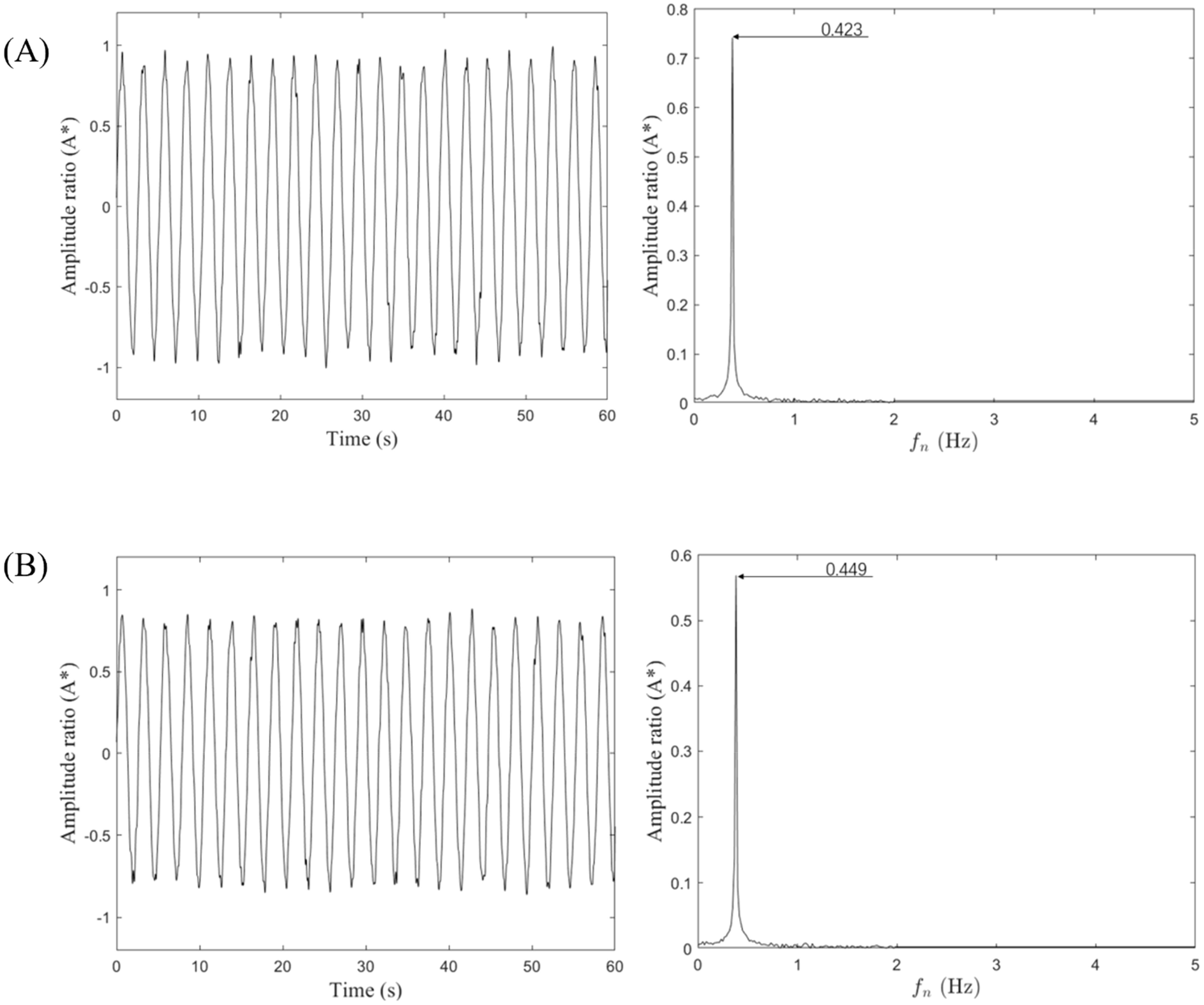
Figure 14. Time domain diagram and frequency domain diagram of the motion state of the Cir-T-Att: (A) Cir-T and (B) Cir-T-Att (Ur = 6.2).
The observed occurrence of alternating vortex leakage in T-shaped cross-section oscillators can be attributed to the migration of the leakage vortex towards the center, subsequent hindrance of vortex motion, reversal of vortex movement, interaction with the boundary layer, and eventual formation of a pattern resembling alternating vortex leakage. This distinct vortex leakage results in increased lift instability of the oscillator, directly affecting the characteristics of the wake vortex. In the context of wake vortex dynamics, it is observed that the vorticity field becomes significantly more complex, leading to the emergence of an extremely unstable wake vortex. Remarkably, the motion of the shear layer exhibits synchronization with the galloping instability. This synchrony between the shear layer and the galloping instability contributes to the complex behavior of the wake vortex.
In the examination of eight distinct cross-section types, a notable observation is made apparent through the frequency ratio peaks depicted in Figure 15A. The Cir-Hex emerge with the most substantial average f* (0.836) among the studied configurations. Throughout the measured range of flow rates, the maximum frequency ratio of the circular cross-section oscillator was found to be 0.868 at Ur of 4, with an average frequency ratio of 0.767. while Cir-Att presents the lowest (0.694). The addition of semicircular appendages generally results in a reduction of the frequency ratio, a trend observed across most sections. However, the Cir-Hex stands as an exception to this prevailing pattern.
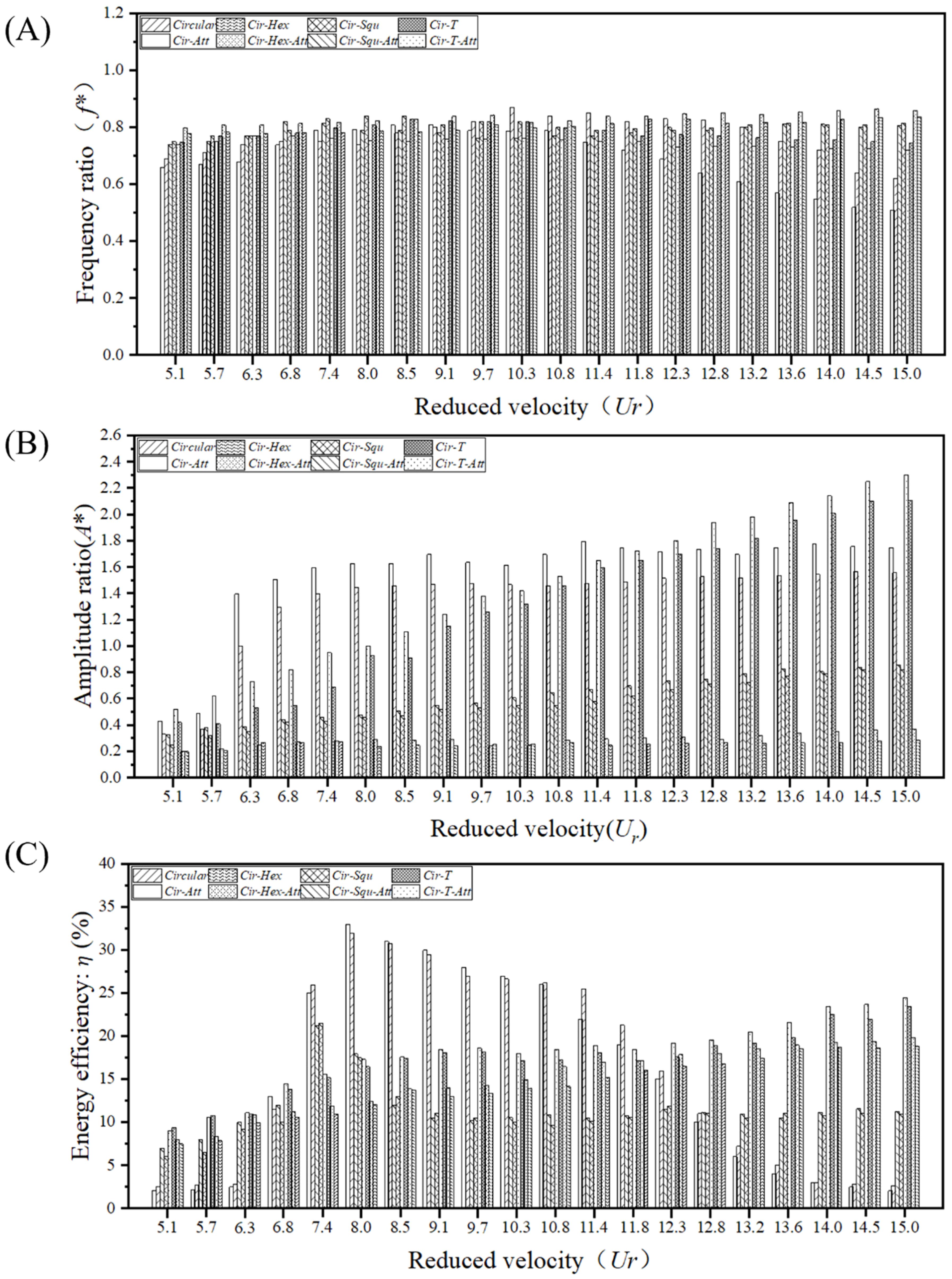
Figure 15. f*, A* and η changing with Ur = 5.1~15.0: (A) frequency ratio comparison chart; (B) amplitude ratio comparison chart; (C) energy capture efficiency comparison chart.
Examining the peak amplitude ratios across various cross-sectional oscillators, The A* was found to be 1.348, 0.258, 0.568, and 1.316 for oscillators of Circular, Cir-Hex, Cir-Squ, and Cir-T, respectively. For oscillators with attached bodies, the A* were 1.556, 0.290, 0.618, and 1.460, respectively. Figure 15B. reveals that Circular configurations stand out with the highest amplitude ratio. Notably, the Cir-Att consistently records the largest amplitude ratio (1.556), the maximum A* was 1.793 when the Ur was 11.4, while the Cir-Hex exhibits the smallest (0.290). This trend is consistently observed within the assessed range of flow velocities, where sections augmented with semicircular appendages consistently showcase enhanced amplitude ratios compared to their original counterparts. The investigation into ocean current energy conversion efficiencies among various cross-sectional oscillators reveals intriguing findings, as illustrated in Figure 15C. Notably, Cir-Att emerges as the most proficient in harnessing ocean current energy (average n is 0.253), exhibiting the highest peak efficiency among all considered configurations (0.328, when the Ur was 8.54). On average, Cir-T-Att showcases the most substantial energy conversion efficiencies (0.302), whereas Cir-Squ records the smallest (0.102). This study encompasses a range of flow velocities, unveiling a consistent trend where sections enhanced with semicircular appendages consistently outperform their original counterparts in ocean current energy conversion efficiency.
5 Conclusions and future work
The FIV capture performance of four typical non-circular cross-section oscillators, along with the case of added rod-like appendages, is evaluated in this study. A total of eight shapes of oscillators are assessed through flow field visualization analysis, FIV motion, and energy utilization across a range of reduced velocities (Ur = 5 ~ 15, Reynolds numbers ranging from 5.041 × 10³ to 7.562 × 10⁴). For the first time, a combination of conventional non-circular cross-section oscillators and symmetrically arranged rods is analyzed comparatively. Derived from our experimental investigations, several noteworthy conclusions can be drawn.
(a) The addition or omission of semicircular appendages to FIV significantly impacts oscillator behavior. On average, the A* and f* of Cir-T was found to be 1.460 and 0.746, however, when no appendage is added, the A* and f* are 1.316, 0.783. At a specific flow rate, an oscillator with appended semicircular structures fosters the initiation and progression of turbulence, causing alterations in the original development of the boundary layer. In this state, the average velocity and flow density within the boundary layer increase, accompanied by a thinner and less stable boundary layer. The resultant rise in frictional resistance amplifies the vibration frequency.
(b) The addition of a semicircular appendage to the oscillator causes a significant shift in the original vortex discharge location, redirecting it away from the formation and development of the leading-edge turbulent boundary layer. Vortices generated by the appendages interact with the turbulence, becoming integrated into the turbulent boundary layer. This interaction increases flow velocity within the boundary layer and reduces its thickness.
(c) In the investigation of various cross-sectional types, the composite section of "circle-polygon-attachments" emerges as a noteworthy contributor to enhanced energy conversion efficiency, surpassing the performance of the "circle-polygon" section. The observation is that within the Ur range of 7 to 12, the Cir-Att attains peak energy collection efficiency (average n is 26.8%). However, in scenarios where the Ur exceeds 12, the Cir-T-Att stands out as the most efficient in harvesting energy (average n is 21.8%).
In conclusion, Cir-Att is more suitable for harnessing hydrokinetic energy when the flow-induced motion (FIM) response occurs in the low flow velocity zone, where vortex-excited vibrations are the primary influencing factor and are significantly dependent on flow velocity. Conversely, Cir-T-Att should be chosen as an oscillator when the FIM response occurs in the relatively high flow velocity zone, where galloping is the predominant influencing factor. This study provides a new perspective for the future optimization of flow-induced kinetic energy conversion and is significant from both scientific and engineering practice viewpoints.
Data availability statement
The raw data supporting the conclusions of this article will be made available by the authors, without undue reservation.
Author contributions
RS: Writing – original draft, Data curation, Formal analysis, Investigation, Methodology, Software. PX: Conceptualization, Writing – review & editing, Supervision, Funding acquisition, Project administration, Resources. CJ: Conceptualization, Methodology, Visualization, Supervision, Writing – review & editing. YZ: Conceptualization, Writing – review & editing, Formal analysis, Methodology, Investigation. HL: Conceptualization, Visualization, Writing – review & editing, Validation, Investigation.
Funding
The author(s) declare financial support was received for the research, authorship, and/or publication of this article. This work was supported by the National Nature Science Foundation of China (Grant No. 52301342).
Conflict of interest
The authors declare that the research was conducted in the absence of any commercial or financial relationships that could be construed as a potential conflict of interest.
Publisher’s note
All claims expressed in this article are solely those of the authors and do not necessarily represent those of their affiliated organizations, or those of the publisher, the editors and the reviewers. Any product that may be evaluated in this article, or claim that may be made by its manufacturer, is not guaranteed or endorsed by the publisher.
References
Adrian R. J., Meinhart C. D., Tomkins C. D. (2000). Vortex organization in the outer region of the turbulent boundary layer. J. fluid Mechanics 422, 1–54. doi: 10.1017/S0022112000001580
Allen J. J., Smits A. J. (2001). Energy harvesting eel. J. fluids structures 15, 629–640. doi: 10.1006/jfls.2000.0355
Barrero-Gil A., Pindado S., Avila S. (2012). Extracting energy from vortex-induced vibrations: a parametric study. Appl. Math. Model. 36, 3153–3160. doi: 10.1016/j.apm.2011.09.085
Bearman P. W. (1984). Vortex shedding from oscillating bluff bodies. Annu. Rev. fluid mechanics 16, 195–222. doi: 10.1146/annurev.fl.16.010184.001211
Bernitsas M. M., Raghavan K., Ben-Simon Y., Garcia E. M. H. (2008). VIVACE (Vortex Induced Vibration Aquatic Clean Energy): A new concept in generation of clean and renewable energy from fluid flow. J. Offshore Mech. Arctic Eng; 130, 10–35. doi: 10.1115/1.2957913
Bishop R. E. D., Hassan A. Y. (1964). The lift and drag forces on a circular cylinder in a flowing fluid. Proc. R. Soc. London. Ser. A. Math. Phys. Sci. 277, 32–50. doi: 10.1098/rspa.1964.0005
Blevins R. D. (1979). Flow-induced vibration in nuclear reactors: a review. Prog. Nucl. Energy 4, 25–49. doi: 10.1016/0149-1970(79)90008-8
Ding L., Zhang L., Wu C., Mao X., Jiang D. (2015). Flow induced motion and energy harvesting of bluff bodies with different cross sections. Energy Conversion Manage. 91, 416–426. doi: 10.1016/j.enconman.2014.12.039
Eshbal L., Kovalev D., Rinsky V., Greenblatt D., van Hout R. (2019). Tomo-PIV measurements in the wake of a tethered sphere undergoing VIV. J. Fluids Structures 89, 132–141. doi: 10.1016/j.jfluidstructs.2019.02.003
Facchinetti M. L., De Langre E., Biolley F. (2004). Coupling of structure and wake oscillators in vortex-induced vibrations. J. Fluids structures 19, 123–140. doi: 10.1016/j.jfluidstructs.2003.12.004
Gu M., Song B., Zhang B., Mao Z., Tian W. (2020). The effects of submergence depth on Vortex-Induced Vibration (VIV) and energy harvesting of a circular cylinder. Renewable Energy 151, 931–945. doi: 10.1016/j.renene.2019.11.086
Han P., Huang Q., Pan G., Qin D., Wang W., Gonçalves R. T., et al. (2023). Optimal energy harvesting efficiency from vortex-induced vibration of a circular cylinder. Ocean Eng. 282, 114869. doi: 10.1016/j.oceaneng.2023.114869
Hsieh S. C., Low Y. M., Chiew Y. M. (2017). Flow characteristics around a circular cylinder undergoing vortex-induced vibration in the initial branch. Ocean Eng. 129, 265–278. doi: 10.1016/j.oceaneng.2016.11.019
Hu G., Tse K. T., Wei M., Naseer R., Abdelkefi A., Kwok K. C. (2018). Experimental investigation on the efficiency of circular cylinder-based wind energy harvester with different rod-shaped attachments. Appl. Energy 226, 682–689. doi: 10.1016/j.apenergy.2018.06.056
Kandasamy R., Cui F., Townsend N., Foo C. C., Guo J., Shenoi A., et al. (2016). A review of vibration control methods for marine offshore structures. Ocean Eng. 127, 279–297. doi: 10.1016/j.oceaneng.2016.10.001
Khalak A., Williamson C. H. (1999). Motions, forces and mode transitions in vortex-induced vibrations at low mass-damping. J. fluids Structures 13, 813–851. doi: 10.1006/jfls.1999.0236
Kim E. S., Sun H., Park H., Shin S. C., Chae E. J., Ouderkirk R., et al. (2021). Development of an alternating lift converter utilizing flow-induced oscillations to harness horizontal hydrokinetic energy. Renewable Sustain. Energy Rev. 145, 111094. doi: 10.1016/j.rser.2021.111094
Lian J., Ran D., Yan X., Liu F., Shao N., Wang X., et al. (2023). Hydrokinetic energy harvesting from flow-induced motion of oscillators with different combined sections. Energy 269, 126814. doi: 10.1016/j.energy.2023.126814
Lin W. J., Lin C., Hsieh S. C., Dey S. (2009). Flow characteristics around a circular cylinder placed horizontally above a plane boundary. J. Eng. mechanics 135, 697–716. doi: 10.1061/(ASCE)0733-9399(2009)135:7(697)
McClure J., Morton C., Yarusevych S. (2019). Forcing function and volumetric flow field estimation for a cylinder undergoing VIV. 13th International Symposium on Particle Image Velocimetry – ISPIV 2019, Munich, German.
Mehmood A., Abdelkefi A., Hajj M. R., Nayfeh A. H., Akhtar I., Nuhait A. O. (2013). Piezoelectric energy harvesting from vortex-induced vibrations of circular cylinder. J. Sound Vibration 332, 4656–4667. doi: 10.1016/j.jsv.2013.03.033
Narendran K., Murali K., Sundar V. (2016). Investigations into efficiency of vortex induced vibration hydro-kinetic energy device. Energy 109, 224–235. doi: 10.1016/j.energy.2016.04.110
Norberg C. (2003). Fluctuating lift on a circular cylinder: review and new measurements. J. Fluids Structures 17, 57–96. doi: 10.1016/S0889-9746(02)00099-3
Opinel P. A., Srinil N. (2020). Application of wake oscillators to two-dimensional vortex-induced vibrations of circular cylinders in oscillatory flows. J. Fluids Structures 96, 103040. doi: 10.1016/j.jfluidstructs.2020.103040
Park H., Mentzelopoulos A. P., Bernitsas M. M. (2023). Hydrokinetic energy harvesting from slow currents using flow-induced oscillations. Renewable Energy 214, 242–254. doi: 10.1016/j.renene.2023.05.110
Rashidi S., Hayatdavoodi M., Esfahani J. A. (2016). Vortex shedding suppression and wake control: A review. Ocean Eng. 126, 57–80. doi: 10.1016/j.oceaneng.2016.08.031
Rostami A. B., Armandei M. (2017). Renewable energy harvesting by vortex-induced motions: Review and benchmarking of technologies. Renewable Sustain. Energy Rev. 70, 193–214. doi: 10.1016/j.rser.2016.11.202
Sun H., Kim E. S., Nowakowski G., Mauer E., Bernitsas M. M. (2016). Effect of mass-ratio, damping, and stiffness on optimal hydrokinetic energy conversion of a single, rough cylinder in flow induced motions. Renewable Energy 99, 936–959. doi: 10.1016/j.renene.2016.07.024
Wang W., Mao Z., Song B., Han P. (2021). Numerical investigation on vortex-induced vibration suppression of the cactus-inspired cylinder with some ribs. Phys. Fluids 33(3). doi: 10.1063/5.0043185
Wang J., Zhao W., Su Z., Zhang G., Li P., Yurchenko D. (2020). Enhancing vortex-induced vibrations of a cylinder with rod attachments for hydrokinetic power generation. Mechanical Syst. Signal Process. 145, 106912. doi: 10.1016/j.ymssp.2020.106912
Watine Y., Gabillet C., Lossouarn B., Deü J. F., Astolfi J. A. (2023). Vortex-induced vibrations of a cantilevered blunt plate: POD of TR-PIV measurements and structural modal analysis. J. Fluids Structures 117, 103832. doi: 10.1016/j.jfluidstructs.2022.103832
Williamson C. H., Govardhan R. (2004). Vortex-induced vibrations. Annu. Rev. Fluid Mech. 36, 413–455. doi: 10.1146/annurev.fluid.36.050802.122128
Xu J., He M., Bose N. (2009). Vortex modes and vortex-induced vibration of a long, flexible riser. Ocean Eng. 36, 456–467. doi: 10.1016/j.oceaneng.2009.01.010
Zhang B., Li B., Fu S., Mao Z., Ding W. (2022). Vortex-Induced Vibration (VIV) hydrokinetic energy harvesting based on nonlinear damping. Renewable Energy 195, 1050–1063. doi: 10.1016/j.renene.2022.06.102
Keywords: flow-induced vibration, non-circular cylinders, particle image velocimetry (PIV), proper orthogonal decomposition (POD), conversion efficiency
Citation: Song R, Xu P, Jiang C, Zhang Y and Li H (2024) An experimental study on flow induced motion and energy harvesting of cylinders with different cross sections. Front. Mar. Sci. 11:1461020. doi: 10.3389/fmars.2024.1461020
Received: 07 July 2024; Accepted: 11 November 2024;
Published: 02 December 2024.
Edited by:
Emiliano Renzi, Northumbria University, United KingdomCopyright © 2024 Song, Xu, Jiang, Zhang and Li. This is an open-access article distributed under the terms of the Creative Commons Attribution License (CC BY). The use, distribution or reproduction in other forums is permitted, provided the original author(s) and the copyright owner(s) are credited and that the original publication in this journal is cited, in accordance with accepted academic practice. No use, distribution or reproduction is permitted which does not comply with these terms.
*Correspondence: Peng Xu, eHVwZW5nQHpqb3UuZWR1LmNu
 Ronglai Song
 Peng Xu
 Changqing Jiang
 Yuan Zhang
 He Li1,4