 Bishwash Khanal
 Madhav Om†
 Sanjay Rijal
 Vaghawan Prasad Ojha
- E.K. Solutions Pvt. Ltd., Lalitpur, Nepal
With the popularity of 3D content like virtual tours, the challenges of 3D data registration have become increasingly significant. The registration of heterogeneous data obtained from 2D and 3D sensors is required to create photo-realistic 3D models. However, the alignment of 2D images with 3D models introduces a significant challenge due to their inherent differences. This article introduces a rigorous mathematical approach to align a 360° image with its corresponding 3D model generated from images with known camera poses followed by texture projection on the model. We use Scale-Invariant Feature Transform (SIFT) feature descriptors enhanced with a homography-based metric to establish correspondences between the faces of a cubemap and the posed images. To achieve optimal alignment, we use a non-linear least squares optimization technique with a custom objective function. Subsequently, the outcomes of the alignment process are evaluated through texturing using a customized raytracing algorithm. The resulting projections are compared against the original textures, with a comprehensive assessment of the alignment's fidelity and precision.
1 Introduction
Recent advancements in data capture technologies have enabled 3D sensors to capture indoor environments to create real-world 3D models. Employing 3D sensors such as light detection and ranging (LiDAR) and time-of-flight (ToF) along with 2D image-capturing sensors has become instrumental in creating photorealistic 3D models. This integration of multi-modal data has become pervasive across diverse domains such as urban scenes (Mastin et al., 2009; Mishra, 2012), medical imaging (Markelj et al., 2010), autonomous driving (Wang et al., 2021), emergency evacuation (Sansoni et al., 2009), and post-event (natural hazard) building assessments (Liu et al., 2020). Notably, such registration approaches are relevant in indoor environments, often achieved using several images (Stamos, 2010) using structure-from-motion (SfM), and manually describing correspondences with similarity transformations for pose estimation. The indoor environment modeling has also opened doors for industrial applications such as virtual tours (Metareal Inc., 2023; Chang et al., 2017) and indoor localization (Arth et al., 2009; Sattler et al., 2011).
In addition to LiDAR and ToF sensors, photogrammetry has emerged as a powerful technique for 3D reconstruction. By combining SfM with multi-view stereo (MVS) (Nebel et al., 2020), photogrammetry can generate detailed 3D models from 2D images. More modern techniques such as neural radiance fields (NeRF) (Mildenhall et al., 2020) and Gaussian Splats (Kerbl et al., 2023) have further advanced the field by enabling high-quality 3D reconstruction from sparse views while addressing complex lighting conditions.
3D models are generally textured using perspective or 360° images after the capture session (throughout the article, we refer to the 360° image in equirectangular planar projection as just 360° image). On the other hand, hardware-embedded sensors like Azure Kinect (Microsoft, 2023) and Intel RealSense (Yang et al., 2017) enable the real-time generation of 3D textures. However, challenges arise during the integration of this heterogeneous data resulting in texture misprojection. This misprojection can occur due to misaligned projection of the posed images onto the 3D model, errors in optimization, and sensor inaccuracies. The inherent sensor inaccuracies and the restricted field of view (FOV) often result in holes and missing textures in the 3D model. Moreover, projecting multiple images onto a 3D model may also introduce blending challenges.
Our proposed method addresses these issues by aligning a 360° image with respect to a 3D mesh using its posed images and their associated features. Our approach uses least squares optimization (LSO) of an objective function defined as the projection of features from posed images on the feature plane of the 360° image. This method not only mitigates texture misprojection but also enhances the overall texture quality by leveraging the comprehensive scene information captured in 360° images.
2 Related works
Various attempts have been made to align 3D models with posed images. Local alignment methods such as iterative point cloud (ICP) registration (Delamarre and Faugeras, 1999) rely on a reliable initialization and are limited in terms of their applicability in the case of unknown relative pose. Russell et al. (2011) presents a combination of global image structure tensor (GIST) descriptors with view-synthesis/retrieval for coarse alignment followed by fine alignment with view-dependent contours matching. However, it has low alignment precision in the case of images with shadings and unreliable features.
Textures generated from RGB-D reconstruction methods are generally sensitive to computational noises such as blurring, ghosting, and texture bleeding. Whelan et al. (2015) and Nießner et al. (2013) use truncated signed distance function (TSDF) volumetric grid running weighted average of multiple RGB images. For each triangle face of a 3D mesh, that is, triangle mesh, the vertex color is determined by the TSDF volumetric grid. Lempitsky and Ivanov (2007) and Allene et al. (2008) utilize pairwise Markov random field as an energy minimization problem to select the optimal image for texturing. On the other hand, Buehler et al. (2001) and Alj et al. (2012a) specify view-dependent texture mapping where the best texture for each triangle mesh is selected based on the minimum angle between the normal of the triangle mesh and the camera directions leveraging rendering methods based on unstructured lumigraph (Gortler et al., 1996) and photoconsistency (Alj et al., 2012b), respectively. However, visual artifacts and distortions are still persistent in such methods. Waechter et al. (2014) use global color adjustment (Lempitsky and Ivanov, 2007) to mitigate visual artifacts due to view projection. Nevertheless, texture bleeding and multi-band blending are challenges for such methods, which can be handled by local texture warping and high-quality non-rigid texture mapping with a global optimization (Fu et al., 2018). However, such approaches face boundary texture deformations and local texture distortions for large geometric errors.
Works on image alignment and texturing have also been done using either direct matching of features (2D-3D matching) (Sattler et al., 2011) or with intermediate image (2D-2D-3D matching) (Sattler et al., 2012). Modern 3D cameras like Azure Kinect (Microsoft, 2023) and Realsense (Yang et al., 2017) use calibration patterns to align 3D data with 2D images (Geiger et al., 2012), but they are not designed to establish relationships between several images. Instead of using multiple images, Sufiyan et al. (2023) use 360° panoramic images for end-to-end image-based localization on both indoor and aerial scenes using deep learning-based approaches. Park et al. (2021) present image-model registration on large-scale urban scenes extracting semantic information from street-view images. However, such stitched posed images or even multiple projections of those images require several treatments such as multi-band blending and exposure compensation (Fu et al., 2018).
Simultaneous localization and mapping (SLAM) algorithms such as RTAB-Map SLAM (Labbé et al., 2018), ORB-SLAM (Mur-Artal et al., 2015), and LSD-SLAM (Engel et al., 2014) give precise poses, but they often fail to achieve high-quality textures. Structure-from-motion (SfM) approaches such as COLMAP (Schönberger and Frahm, 2016; Schönberger et al., 2016) and OpenMVS (Cernea, 2020) are widely used for 3D reconstruction from multiple images. These methods involve feature extraction, matching, and triangulation to create 3D models. While effective, they often require a large number of overlapping images and computational resources.
Matterport (Chang et al., 2017) uses three stationary structured cameras in a hardware enclosure to create a 3D mesh and 360° images. Matterport3D is particularly relevant as it uses posed images and 360° images for texturing 3D meshes, similar to our approach, making it a suitable baseline for comparison. Similarly, Metareal (Metareal Inc., 2023) utilizes a 360° camera to capture data, creating a 3D model through the detection of line segments manually within the 360° images. Such advancements not only address challenges in data registration but also open avenues for innovative applications across various domains.
We propose a pipeline that uses a single 360° image for texturing that better encompasses and represents the scene information. Modern 360° cameras like RICOH THETA V (Aghayari et al., 2017) are capable of generating HDR images, which further improve the texture quality. Addressing the limitations of SLAM algorithms, we use the relationship between SIFT features (Lowe, 2004) in posed images and the cubemap face of a 360° image to minimize a custom objective function that better represents the 3D nature of the data than usual reprojection errors. Rather than computing 3D feature descriptors as suggested in Panek et al. (2023), we use camera extrinsics for projecting 2D features on a 3D plane. For 360° images, camera intrinsics are not required. The textures from the 360° image are finally projected using a custom raytracing pipeline.
In the following sections, we provide an overview of our method (Section 3) followed by a rigorous mathematical and geometrical interpretation of our approach focused on alignment estimation (Section 4), feature projection (Section 5), least squares optimization (LSO) (Section 6), and texturing (Section 7). Section 8 shows the evaluation of the metrics, performance of our approach, and comparison with RTAB-Map, COLMAP, and Matterport3D as the baseline. We chose RTAB-Map as we use its posed images for alignment, making it a suitable comparison for texture quality. COLMAP, on the other hand, is chosen as a baseline, for our goal is similar to SfM algorithms. Throughout the article, we refer to 2D perspective RGB images with known camera poses as “posed images”.
3 Method overview
The overall pipeline is illustrated in Figure 1. Given a 360° image and a set of posed images , our objective is to achieve an accurate alignment between and the 3D mesh generated from . We obtain the pose for each image Qi and a dense 3D mesh from RTAB-Map, which uses iterative sparse bundle adjustment and loop closure algorithms (Labbe and Michaud, 2014) for optimal image registration.

Figure 1. Overall system block diagram of our approach.
Using the front face from the cubemap projection of a , we estimate the best match-posed image followed by feature preprocessing, which involves the extraction of SIFT features (Lowe, 2004), image filtering, and 2D to 3D feature projection. Applying LSO on the processed features provides an optimal transformation (Topt) for , which is subsequently used to align the with the 3D mesh for texturing. In summary, the process involves: (i) obtaining an initial transformation Tinit for a given , (ii) projecting 2D SIFT features from and on a 3D space, (iii) using these features and Tinit to obtain Topt through the optimization of the point-line distance using the LSO, and (iv) projection of on the 3D mesh using raytracing algorithm.
4 Initial estimation
Since we use least squares optimization for obtaining the optimal transformation Topt of , we need an initial estimate Tinit of that transformation. Rather than using random assignment, we estimate Tinit based on the number of feature matches between a posed image and the front face Sf of . Out of the six faces of the cubemap, we take the front face for initial estimation. However, the choice of the cubemap face can be arbitrary. This choice only impacts the estimation of Tinit as we later use features from all the faces for optimization. We search for the best matching image to Sf as depicted in Figure 2. We leverage SIFT feature descriptor, for its scale and rotation invariance. We compare the SIFT features from Sf, Fi(Sf) to those from all Cis, Fi(Ci).

Figure 2. Cubemap projection of (A), its Sf (B), and the corresponding Cbm (C).
Instead of the conventional way of using only the number of feature matches to determine the best match of Sf among Ci. Let a be the number of “good” feature matches between Fi(Sf) and Fi(Ci), where a “good” match is determined using Equation 1. Let b be the Frobenius norm (Horn and Johnson, 1990) of the homography matrix between the keypoints from Sf and the corresponding matched keypoints from Ci. The image (Cbm = Ci) with max(amb−n) is chosen as the best matching image among . Here, m and n are constants determined empirically.
where Fi(Ci) and Fj(Ci) are the features in Ci representing the first and the second best SIFT feature matches between Sf and Ci, respectively.
By incorporating the Frobenius norm, our method balances the number of good feature matches and the geometric transformation between Sf and Ci. In general, given a homography matrix between Sf and Ci, the Frobenius norm quantifies the amount of geometric transformation including rotation, translation, and scaling, required to map points from one image to the corresponding points in the other image.
We specifically select Cbm by maximizing the metric amb−n, ensuring that the selected image not only has a high number of feature matches but also requires minimal transformation, resulting in a more accurate and reliable alignment. The comparison between the alignment results from the metrics max(a) and max(amb−n) is described in Section 8.1.1.
For our experiment, we find m = n = 2 as appropriate choices. This choice ensures a quadratic relationship, balancing the influence of the number of good matches and the Frobenius norm maintaining the simplicity of the calculations. The initial estimate Tinit is determined by the inversion of the pose Qbm of Cbm. This accounts for the difference between the world and camera coordinate systems.
5 Feature projection
It is essential to address the inherent challenge posed by the difference in dimensions between Fi(Ci) and the 3D nature of Tinit, so we project 2D features into 3D space. Moreover, Fi(Sf)s originally in the spherical coordinate system require transformation to the Cartesian coordinate system.
5.1 2D to 3D projection
We use camera intrinsic matrix K, and extrinsic matrix [R|t] as the inverse of the pose matrix Q = {Qi}, which maps a 2D pixel coordinate of the respective SIFT feature Fi(Ci) to a 3D point Pi as given by Equation 2 (Imatest, 2023):
where R is the rotation matrix, t is the translation vector, and (u, v) are pixel coordinates in (x, y) image axes along the width and height of the image.
This method of 2D to 3D projection provides an equivalent representation of the features for our algorithm, thus eliminating the dependency on depth maps. Therefore, we choose this projection method over the use of depth information. Moreover, it is efficient in terms of the runtime of the algorithm. Even among the matched feature points Pi(Ci), not all of them are spatially close to each other, as they may be distributed in various directions in the 3D space. Such outliers can affect the performance of LSO. Hence to identify the clustered features , we use a naive outlier rejection algorithm that excludes all Pi(Ci) lying outside a sphere of radius 0.5 around Pi(Sf) as shown in Equation 3.
5.2 Spherical to cartesian projection
Let (θ, ϕ) be the unique longitude and latitude of a feature Fi(Sf). We can project 2D features Fi(Sf)s onto a unit sphere using spherical to Cartesian coordinate conversion.
In the world coordinate system (WCS), coordinates are typically projected along the +X-axis, whereas in the camera's coordinate system, they are projected along the +Z-axis. To align these different conventions, we apply a correction using a rotation matrix Rcorr. This matrix rotates the spherical coordinate by 90° on both X and Z axes. This correction ensures that the spherical points from Sf are properly aligned with when transformed using Tinit.
All these processes of feature projection are repeated for the features on all the cubemap faces excluding the top and bottom as they generally contain ceilings and floors with a lower number of features.
6 Least squares optimization
As a Fi(Sf) can have matches across different Cis, we augment Pi(Sf) to match followed by decomposition of Tinit into an initial state matrix ρ0 = (tx, ty, tz, α, β, γ). The state matrix ρ represents six degrees of freedom (dof) of the transformation matrix T. Equations 5 and 6 give the relationship between T and its ρ.
where s and c represent sine and cosine functions respectively.
Since, the domain points Pi(Sf) and observation points are taken from two different projections, that is, spherical surface (360° image) and plane (posed images) respectively, we implement an objective function ei representing the perpendicular distance D from the observation point (N) to the line drawn by joining [tx, ty, tz] and the predicted point (Nagwa, 2023) as shown in Figure 3. We also refer to this objective function as an error function as it quantifies the error as the distance between Pi(Sf) and the corresponding .
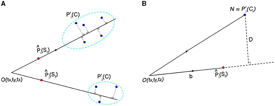
Figure 3. The red and blue points represent features from the cubemap faces and their corresponding matched features across different posed images respectively (A). The goal is to minimize the perpendicular distance (D) between the line passing through red () and blue points (). D is calculated as the projection of on , a unit vector along (B), using the Equation 7.
While the conventional approach in reconstruction tasks is to minimize the reprojection error, we opt to minimize the point-line distance due to distinct advantages. The point-line distance method maintains dimensional consistency between our spherical and Cartesian coordinates, accurately captures the geometric distribution of features, and reduces computational complexity. It consequently leads to a faster convergence.
We obtain the final (optimal) state matrix ρopt from ei and its Jacobian Ji using the Levenberg–Marquardt algorithm (Marquardt, 1963) followed by iterative training of a stochastic gradient descent (SGD) (Rumelhart et al., 1986) algorithm with a small learning rate λ as shown in Equation 9:
where ρ = (tx, ty, tz, α, β, γ).
where I is an identity matrix of the same order as that of H. Finally, Topt is computed from ρopt using Equation 5.
7 Texture projection
Given a 3D mesh with vertices V = (x, y, z), we correct V with respect to Topt followed by a texture correction matrix Ttexture, which ensures the texture projection as per the Manhattan World assumptions. In our case, the texture correction matrix has an Eulerian angle of - along both the X and Y axes.
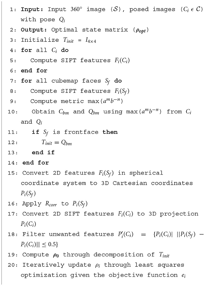
Algorithm 1. 360° image alignment algorithm.
We convert V′ to polar coordinates (θ, ϕ). Since the 360° images we use are in equirectangular projection, we adjust (θ, ϕ) as per the dimensional ratio of equirectangular map (2:1) such that the (θ, ϕ) represent the (latitude, longitude). We then convert (latitude, longitude) to pixel coordinates (u, v) as per the standard coordinate transformation (Equations 11 and 12).
360° images contain the same textures on the extreme north pole and extreme south pole of a uv map and as a result, while assigning textures to each triangle mesh, the position of triangle mesh vertices beyond or at the poles are interpreted as the position on the opposite side of the uv map as shown in Figure 4.
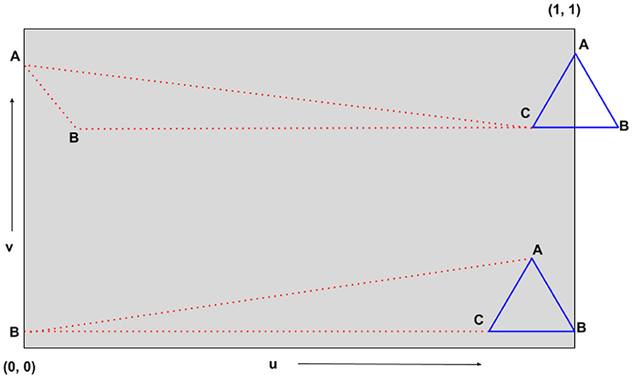
Figure 4. Geometric interpretation of the issue beyond or at poles during 360° image texturing. The triangles represent the triangle meshes on which textures are to be projected (blue represents the actual position and red represents the apparent position). Due to the position of vertex B (in blue triangles) near the poles of the uv map, the blue triangles are interpreted as red triangles.
Due to the periodic nature of 360° image textures, the vertices of blue and red triangles are actually the same. As a result, instead of projecting textures on the blue triangle, the same textures are projected on the red triangle. This introduces rainbow-like artifacts for all such triangles as shown in Figure 5. This is a common problem with most texturing algorithms. To solve this issue, we utilize the same periodic nature of 360° images—we translate the triangles along the u-axis1 by a translation factor of 0.5 for such cases. This translation repeats the (u, v) coordinates in the region beyond the poles thus correctly identifying the actual position of vertices of the triangle to be textured.
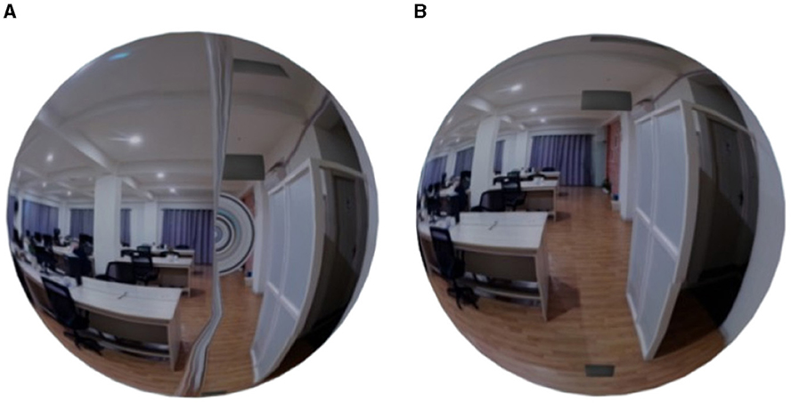
Figure 5. Rainbow-like artifacts (A) due to the texture projection on red triangles instead of blue triangles (from Figure 4) observed on a spherical mesh. The artifacts are removed (B) leveraging the periodic nature of 360° image textures.
8 Results
8.1 Evaluation
8.1.1 Best match parameter evaluation
As explained in Section 4, we evaluate the performance of our algorithm using two distinct metrics: max(a) and max(a2b−2) to identify Cbms. Figure 6 and Table 1 show that max(a2b−2) consistently yields lower loss compared to max(a) during LSO. Moreover, as shown in Figure 7, the initial transformation estimated using Cbm based on max(a2b−2) gives significantly robust alignment compared to the estimation based on max(a). On all the scenes, the transformations obtained with the metric max(a2b−2) show a better alignment of textures with the 3D mesh than those with the metric max(a). This emphasizes the critical role of parameter b and max(a2b−2) metric, even after obtaining the maximum number of good feature matches between the Sf and Ci.
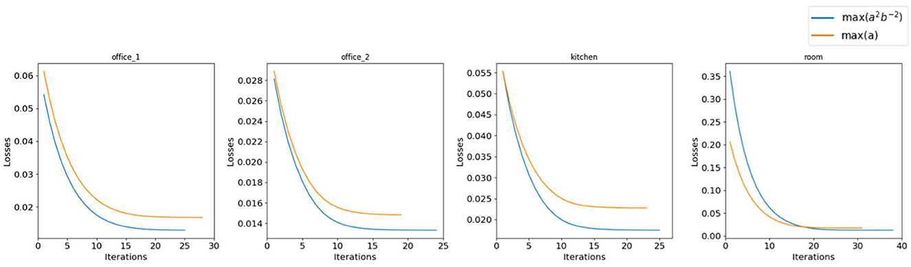
Figure 6. Performance comparison of metrics max(a) and max(a2b−2) on the real-world dataset. The metric max(a2b−2) shows better performance than max(a) both in terms of loss and convergence rate.
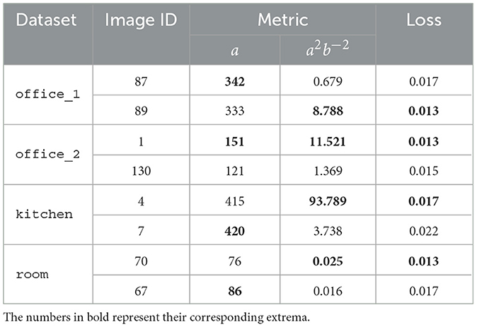
Table 1. Parameters and metrics for Cbm selection as discussed in Section 4 with their LSO losses.
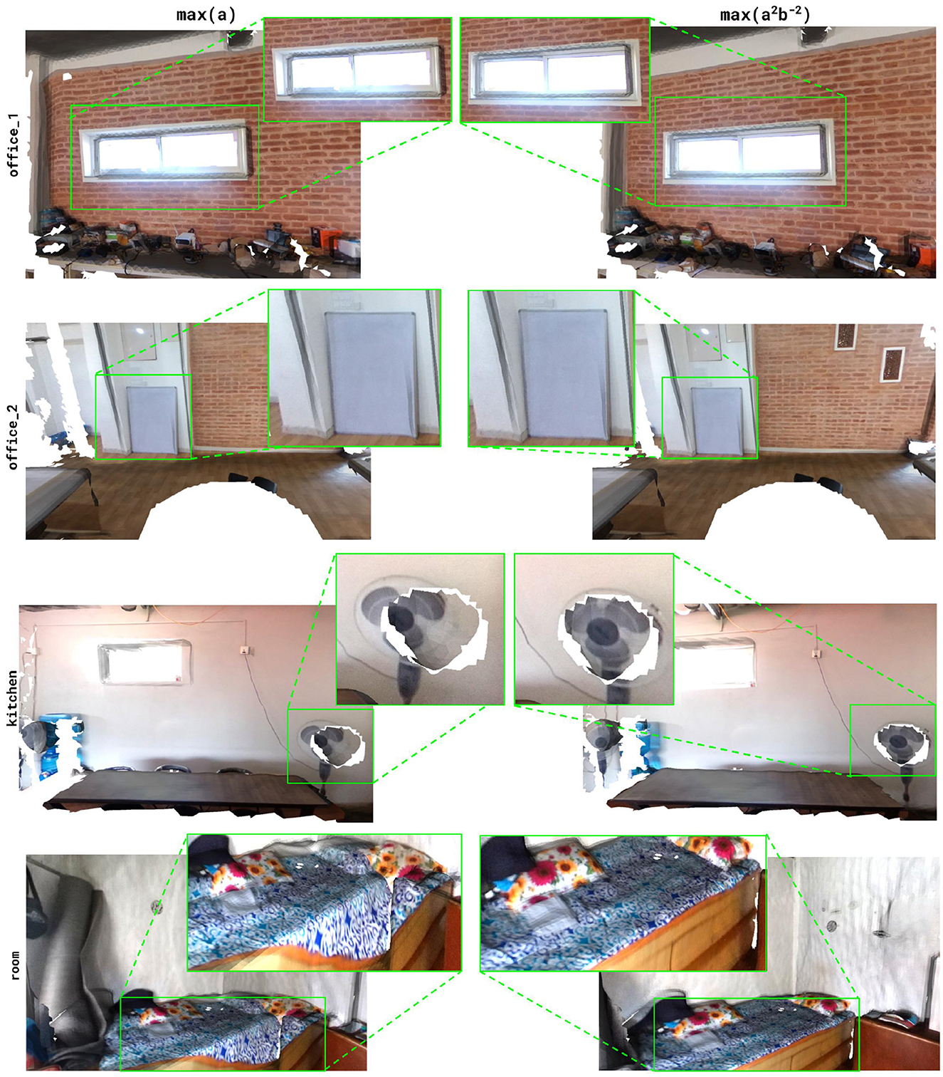
Figure 7. Comparison of texture alignment with 3D mesh using the transformations obtained with metrics max(a) and max(a2b−2). The metric max(a2b−2) yields more precise alignment than max(a). The missing triangle mesh regions (white) are due to the holes in the input 3D mesh which we later compensate for using the hole-filling algorithm as described in the Appendix 1.
8.1.2 Feature alignment and pose optimization
With the transformation Tinit converted to ρ0 using Equation 5, the algorithm leverages standard SGD for the LSO, with a learning rate of 1e−3. The initial alignment disparities between Pi(Sf) and for a given face of the cubemap are evident as indicated by the green ellipses in Figure 8. However, these disparities diminish progressively with iterations. A closer analysis reveals that due to the selection of the front face features for initial estimation, Pi(Sf) are initially more tilted toward one side of the 3D features. However, the inclusion of features from all the faces of the cubemap for optimization eventually results in a more centralized feature localization.
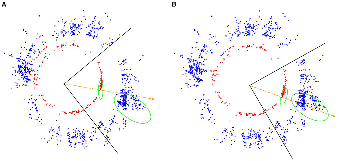
Figure 8. (blue) and Pi(Sf) (red). (A) shows the position of 3D features before optimization and (B) shows their position during initialization. The black boundary lines represent one of the cubemap faces (front face), the green ellipses represent the corresponding features in and Pi(Sf), and the orange-dotted arrows represent the rays traced from the features for texturing.
As illustrated in Figure 9, our algorithm demonstrates consistent loss reduction across all the scenes over successive iterations further supporting the performance of the algorithm. Moreover, the green bounding boxes highlight the region of interest (ROI) for comparison of the precision of alignment for initial, intermediate, and final iterations. This shows a significant improvement in the alignment, ultimately giving the least error at the point of convergence. The final iteration typically yields the most accurate alignment, although instances of local minima convergence can be observed. In such cases, early stopping proved beneficial by selecting transformations from the intermediate iterations that offered better alignment.
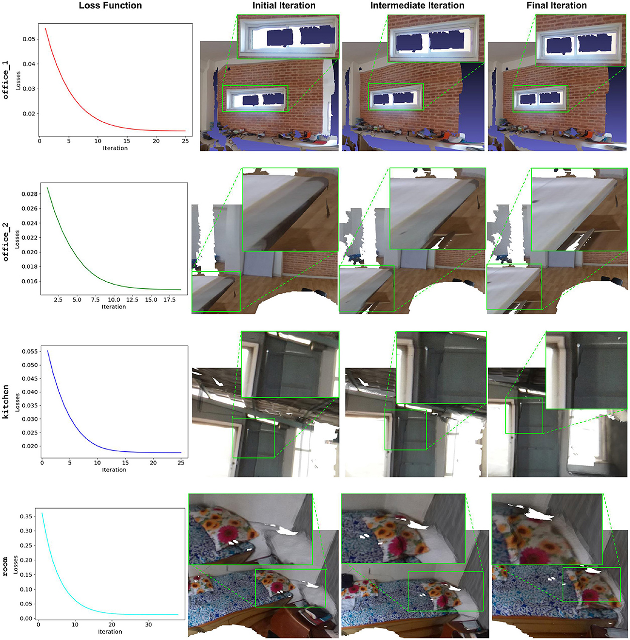
Figure 9. Performance of our approach at different iterations during LSO. The loss function exponentially decreases for all the scenes. Comparing the initial, intermediate, and final iterations shows significant improvement in the alignment process as highlighted by the green ROI.
8.2 Experiments
8.2.1 Comparison on real-world scenes
We use Azure Kinect (Microsoft, 2023) to capture the posed images () for its ability to capture detailed 3D data with minimal noise in depth maps (Rijal et al., 2023). As shown in Figure 10, we mount the Azure Kinect camera on a tripod facilitating the controlled rotation across the different pans and tilts to achieve nearly 360° panoramic coverage of a scene. However, due to hardware constraints, we exclude the nadir and the zenith corresponding to the tilts beyond a range of [−75°, 75°]. We utilize RTAB-Map (Labbé et al., 2018) SLAM pipeline to obtain posed images and 3D meshes. Following this, we position the RICOH Theta camera on the same tripod to capture 360° images maintaining similar levels to the Azure Kinect.
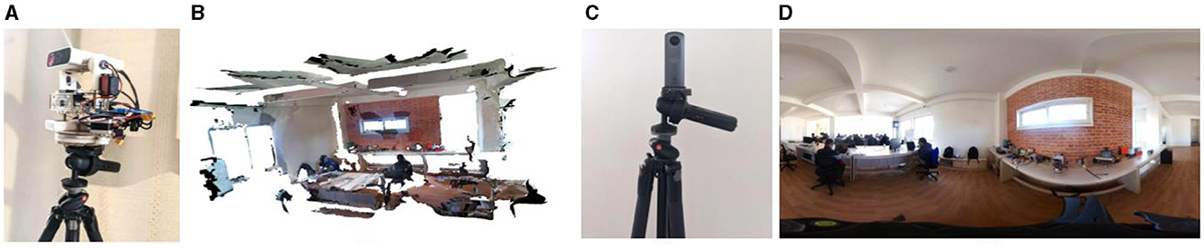
Figure 10. 3D mesh (B) obtained from Azure Kinect mounted in a tripod with custom-designed hardware (A) and the 360° image in equirectangular projection (D) from RICOH THETA V (C). Azure Kinect and RICOH Theta V are mounted on the same tripod maintaining similar levels.
The problem of estimating the transformation for Sf using pre-registered Cis resembles standard SfM approaches where new images can be integrated into an existing system of posed images by extracting features, matching them with pre-registered images, and then triangulating the feature points to obtain the pose of the newly integrated image. We compare our texture alignment results with those of COLMAP (Schönberger and Frahm, 2016; Schönberger et al., 2016), a popular SfM tool. We utilize COLMAP's feature extraction and matching, update the camera intrinsics, and triangulate the matched features to integrate Sf into the existing SLAM system of Cis. Using the transformation calculated for Sf in this system, we align the 360° image for texturing. Figure 11 shows the comparison of final alignment quality between COLMAP and our approach.
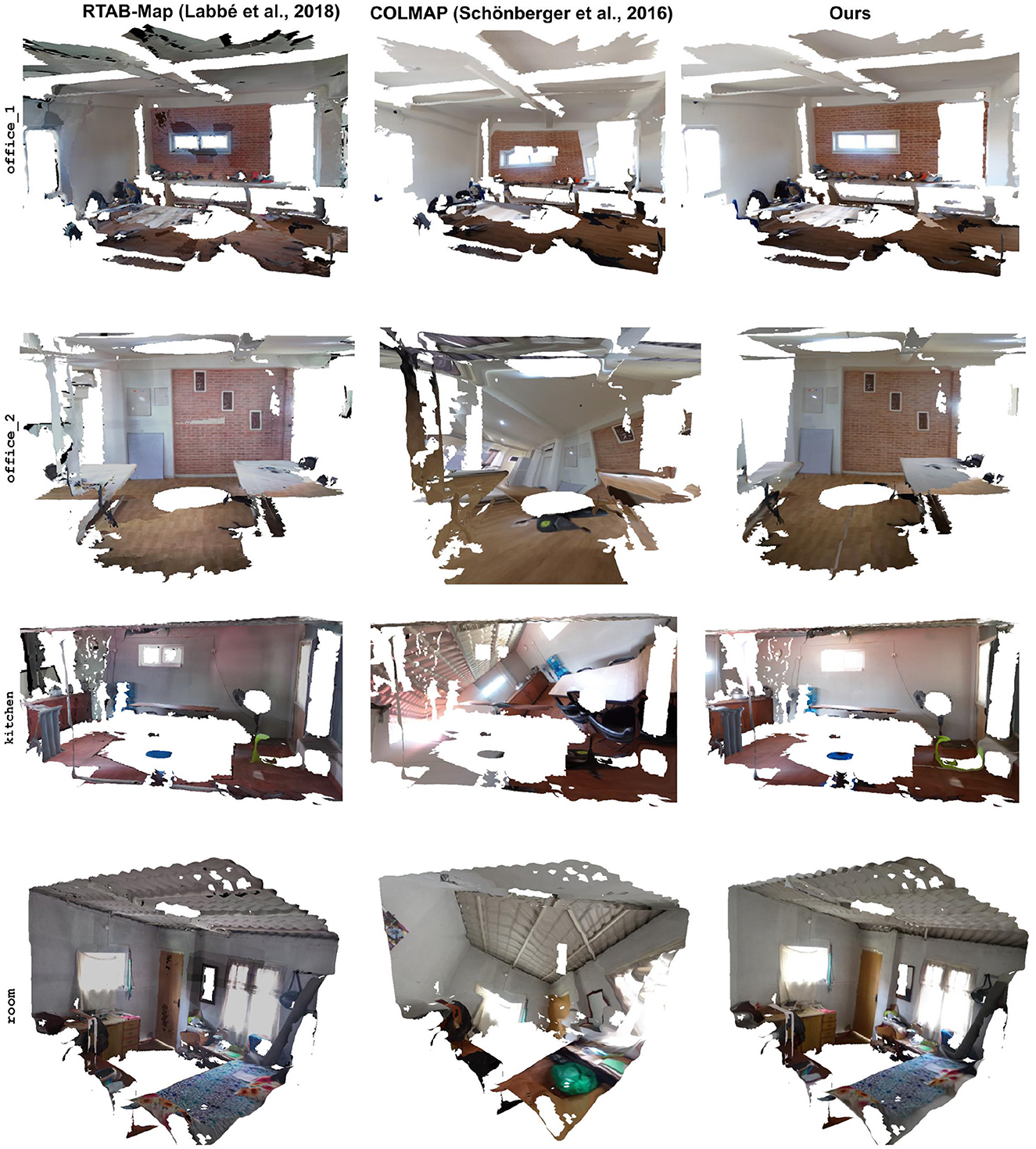
Figure 11. Texture alignment results from different approaches: original 3D mesh from RTAB-Map (left), re-textured mesh with transformation obtained from COLMAP (middle), and our approach (right).

Algorithm 2. Raytracing algorithm.
COLMAP primarily relies on traditional SfM techniques designed for perspective images, which limits its ability to register an entire 360° image within a SLAM system of perspective-posed images. Therefore, the front face is chosen as the reference for the 360° image. While other faces can also be registered within the same system, they do not contribute to the overall alignment of the 360° image and act independently. This reliance on only the front face for image registration causes COLMAP to localize features toward one side, neglecting features from other faces. In contrast, our approach incorporates features from all faces, resulting in a more robust and accurate feature alignment as shown in Figure 8. This feature alignment is further corroborated by Figure 11, which shows better texture alignment with our approach.
Specifically, our method consistently achieves higher values in image similarity metrics such as PSNR (peak signal-to-noise ratio) and structural similarity index (SSIM), indicating better alignment quality. PSNR measures the ratio between the maximum possible value of a pixel and the power of the noise affecting the image, with higher values representing better texture alignment. SSIM assesses the similarity between two images, with higher values indicating greater structural similarity. Moreover, our approach yields lower values in the perceptual similarity metric LPIPS (Learned Perceptual Image Patch Similarity), which measures perceptual differences between images, with lower values indicating better perceptual alignment. The results presented in Table 2 clearly demonstrate that our approach outperforms COLMAP.
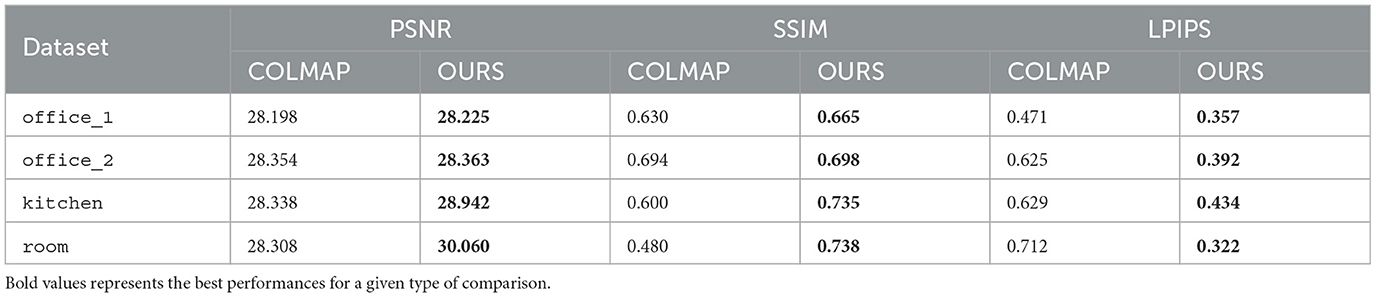
Table 2. Comparison of PSNR, SSIM, and LPIPS metrics between COLMAP and our approach on the real-world dataset.
For calculating these metrices, we use the 2D projection of the 3D mesh region, which corresponds to the front face of its 360° image. We take the region selected from 3D mesh generated by RTAB-Map as the reference, and compare with COLMAP and our approach on the same region from the texture-projected mesh. An example of images used for reference and comparison on office_2 scene is shown in Figure 12.
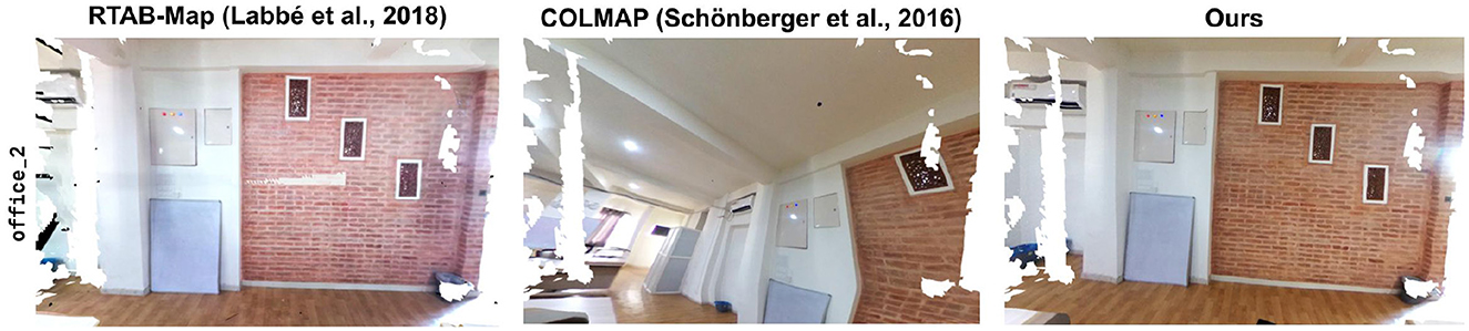
Figure 12. Reference image obtained from the 3D mesh generated with RTAB-Map used for comparing similarity metrics on COLMAP and our approach.
8.2.2 Comparison with Matterport3D dataset
We also evaluate our algorithm on the Matterport3D dataset (Chang et al., 2017), which contains 90 RGBD real-world scenes featuring 10,800 panoramic views. Due to the differences in the texture alignment and projection methods used by Matterport3D and our approach, in this section, we present a performance evaluation of our approach on the Matterport3D dataset instead of a direct comparison. Leveraging posed images, depth maps, poses, and intrinsics from the dataset, we construct a TSDF volume for the 3D mesh of a scene to establish a baseline for evaluation.
The number of posed images per scene in the Matterport3D dataset is notably less (18) than what our algorithm typically requires (~60). Due to the inherent nature of SGD, the limited number of posed images results in a reduced set of features for optimization, posing a risk of overfitting the objective function. This can cause the algorithm to favor regions with dense feature points, allowing the pose of the 360° image to drift away from the ideal uniform alignment toward the center of projection of the ground truth mesh. To address this problem, we implement early stopping during the optimization process to ensure minimal drift.
Figure 13 illustrates the performance of our algorithm on four different scenes from the Matterport3D dataset selected based on the presence of walls, which facilitates better comparison of texture projection including potential misalignments. While our algorithm shows overall effectiveness on a large scale, a closer inspection reveals subtle drifts from the ground truth textures, especially around the center of projection. These misalignments are quantified using PSNR, SSIM, and LPIPS metrics in Table 3. As the ground truth poses are available for the Matterport3D dataset, we also compute the pose drift of our approach using MSE.
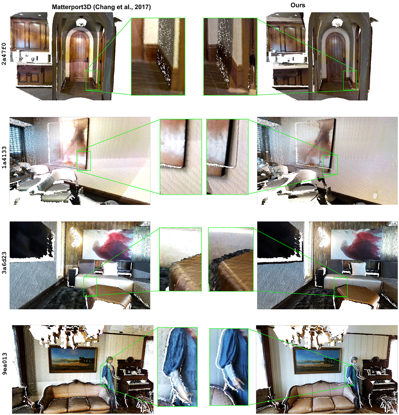
Figure 13. Performance of our algorithm with a few scenes (identified by their truncated panorama_uuid) from Matterport3D dataset. The highlighted regions show areas of minor misalignments from our approach as compared to the textures from Matterport3D.
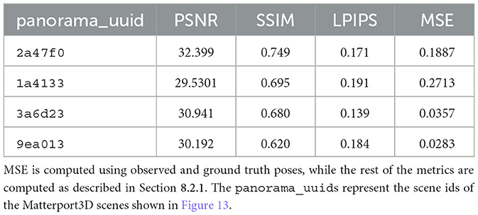
Table 3. Performance metrics for our algorithm on the Matterport3D dataset.
9 Discussion
In this article, we introduced a novel methodology for aligning a 360° image with its corresponding 3D mesh using a custom objective function for least squares optimization. The results show that our approach significantly reduces the spatial drift between the 3D mesh and the 360° image. The precision of this alignment is further visualized from the alignment of features extracted from the posed and 360° images. For the critical task of texture projection, we introduced a customized raytracing algorithm. Our approach allows for accurate texture projection using the optimal alignment transformation while addressing the inherent texturing issue (rainbow-like artifacts) at the poles of 360° images, thus enhancing the quality of the textured mesh.
We also evaluated our approach with baseline approaches such as RTAB-Map, COLMAP, and Matterport3D. Compared with the RTAB-Map, our method demonstrated better texture quality measured using image similarity metrics. Unlike SfM approaches like COLMAP, our approach takes into account the features from all the cubemap faces, thus preventing the local convergence of SGD loss. As a result, the transformations obtained from our approach provided a better texture alignment than the COLMAP. With the Matterport3D dataset, our method showed commendable performance, albeit with minor misalignment issues. This misalignment is primarily due to the limited number of images available for each scene in the Matterport3D dataset. We also quantified the performance of our approach with standard image similarity metrics such as PSNR, SSIM, LPIPS, and MSE. The implications of our approach hold promise for advancing domains such as 3D reconstruction and virtual tours to enhance realism and accuracy.
The current pipeline is effective but not without limitations. One significant challenge is the tendency for alignment to skew toward areas with a higher concentration of SIFT features, a limitation not unique to our method but inherent in classical feature alignment techniques. Moreover, while deep learning approaches like Superpoint (DeTone et al., 2018) offer improved performance, they are constrained in textureless regions. The computational intensity of our least squares optimization, particularly due to its numerous non-linear components, is a potential area for further refinement. Additionally, due to the nature of 360° image, texturing is best viewed from the center of projection and gradually warps with increasing distance from the center.
10 Conclusion and future works
Our proposed methodology for 360° image alignment with corresponding 3D mesh and a customized texture projection algorithm holds promise for advancing domains such as 3D reconstruction and virtual tours. Despite its limitations regarding alignment tendencies for a limited number of posed images and computational intensity, our approach is comparable to the baseline methods and outperforms the widely used SfM and reconstruction approaches in the industry such as COLMAP and RTAB-Map.
Our future research is to optimize our pipeline further and extend its applications. Initially conceived for indoor environment modeling in virtual tours, we aim to conduct rigorous testing of our methodology in such applications in the near future. The current hardware limitations, especially the Azure Kinect's restricted distance coverage, often cause odometry loss during outdoor scene captures. Addressing this limitation, future research will explore alternative hardware with wider distance coverage capabilities, thus enhancing our pipeline's suitability for outdoor environments as well.
Data availability statement
The raw data supporting the conclusions of this article will be made available by the authors, without undue reservation.
Author contributions
BK: Conceptualization, Data curation, Formal analysis, Investigation, Methodology, Software, Validation, Visualization, Writing – original draft, Writing – review & editing. MO: Conceptualization, Formal analysis, Investigation, Methodology, Software, Supervision, Writing – review & editing. SR: Data curation, Formal analysis, Investigation, Methodology, Software, Validation, Visualization, Writing – original draft, Writing – review & editing. VO: Project administration, Resources, Supervision, Writing – review & editing.
Funding
The author(s) declare that no financial support was received for the research, authorship, and/or publication of this article.
Acknowledgments
The authors would like to extend their sincere gratitude to E.K. Solutions Pvt. Ltd., Nepal for not only providing invaluable support and resources but also for granting the opportunity to conduct this research. Additionally, the authors would like to express their appreciation to the entire AI team at E.K. Solutions, whose support and constructive feedback contributed significantly to the refinement of this research.
Conflict of interest
BK, MO, SR, and VO were employed by E.K. Solutions Pvt. Ltd.
Publisher's note
All claims expressed in this article are solely those of the authors and do not necessarily represent those of their affiliated organizations, or those of the publisher, the editors and the reviewers. Any product that may be evaluated in this article, or claim that may be made by its manufacturer, is not guaranteed or endorsed by the publisher.
Footnotes
1. ^We do not translate along the v-axis as we have a single 360° image, however, in case of vertically stacked 360° images (such as atlas) translation along v-axis is required.
References
Aghayari, S., Saadatseresht, M., Omidalizarandi, M., and Neumann, I. (2017). “Geometric calibration of full spherical panoramic Ricoh-Theta camera,” in ISPRS Annals of the Photogrammetry, Remote Sensing and Spatial Information Sciences; IV-1/W1. 4 (Göttingen: Copernicus GmbH), 237–245. doi: 10.5194/isprs-annals-IV-1-W1-237-2017
Alj, Y., Boisson, G., Bordes, P., Pressigout, M., and Morin, L. (2012). “Multi-texturing 3D models: how to choose the best texture?,” in 2012 International Conference on 3D Imaging (IC3D) (Liege: IEEE), 1–8. doi: 10.1109/IC3D.2012.6615115
Alj, Y., Boisson, G., Bordes, P., Pressigout, M., and Morin, L. (2012). “Space carving MVD sequences for modeling natural 3d scenes,” in Proceedings of the 23rd annual conference on computer graphics and interactive techniques (SPIE, ACM), 42–56. doi: 10.1117/12.908608
Allene, C., Pons, J.-P., and Keriven, R. (2008). “Seamless image-based texture atlases using multi-band blending,” in 2008 19th international conference on pattern recognition (Tampa, FL: IEEE), 1–4. doi: 10.1109/ICPR.2008.4761913
Alliez, P., and Fabri, A. (2016). “CGAL: the computational geometry algorithms library,” in ACM SIGGRAPH 2016 Courses (ACM), 1–8. doi: 10.1145/2897826.2927362
Arth, C., Wagner, D., Klopschitz, M., Irschara, A., and Schmalstieg, D. (2009). “Wide area localization on mobile phones,” in 2009 8th IEEE international symposium on mixed and augmented reality (Orlando, FL: IEEE), 73–82. doi: 10.1109/ISMAR.2009.5336494
Buehler, C., Bosse, M., McMillan, L., Gortler, S., and Cohen, M. (2001). “Unstructured lumigraph rendering,” in Proceedings of the 28th annual conference on Computer graphics and interactive techniques (New Yor, NY: ACM), 425–432. doi: 10.1145/383259.383309
Cernea, D. (2020). OpenMVS: Multi-View Stereo Reconstruction Library. https://cdcseacave.github.io/openMVS (accessed November 21, 2023).
Chang, A., Dai, A., Funkhouser, T., Halber, M., Niebner, M., Savva, M., et al. (2017). “Matterport3D: learning from RGB-D data in indoor environments,” in 2017 International Conference on 3D Vision (3DV) (Qingdao: IEEE), 667–676. doi: 10.1109/3DV.2017.00081
Delamarre, Q., and Faugeras, O. (1999). 3D articulated models and multi-view tracking with silhouettes. Proc. Seventh IEEE Int. Conf. Comput. Vis. 2, 716–721. doi: 10.1109/ICCV.1999.790292
DeTone, D., Malisiewicz, T., and Rabinovich, A. (2018). “Superpoint: self-supervised interest point detection and description,” in Proceedings of the IEEE conference on computer vision and pattern recognition workshops (Salt Lake City, UT: IEEE), 224–236. doi: 10.1109/CVPRW.2018.00060
Engel, J., Schoeps, T., and Cremers, D. (2014). LSD-SLAM: large-scale direct monocular SLAM. Eur. Conf. Comput. Vis. 8690, 1–16. doi: 10.1007/978-3-319-10605-2_54
Fix, E., and Hodges, J. L. (1951). Discriminatory Analysis. Nonparametric Discrimination: Consistency Properties. San Antonio, TX: USAF School of Aviation Medicine, Randolph Field, Texas.
Fu, Y., Yan, Q., Yang, L., Liao, J., and Xiao, C. (2018). “Texture mapping for 3D reconstruction with rgb-d sensor,” in Proceedings of the IEEE conference on computer vision and pattern recognition (Salt Lake City, UT: IEEE), 4645–4653. doi: 10.1109/CVPR.2018.00488
Geiger, A., Moosmann, F., Car, O., and Schuster, B. (2012). “Automatic camera and range sensor calibration using a single shot,” in 2012 IEEE International Conference on Robotics and Automation (Saint Paul, MN: IEEE), 3936–3943. doi: 10.1109/ICRA.2012.6224570
Gortler, S. J., Grzeszczuk, R., Szeliski, R., and Cohen, M. F. (1996). The Lumigraph. New York, NY: Association for Computing Machinery.
Horn, R. A., and Johnson, C. R. (1990). Matrix Analysis. Cambridge: Cambridge University Press. Available at: https://books.google.com.np/books?id=PlYQN0ypTwEC (accessed June 14, 2023).
Imatest (2023). Geometric Calibration: Projective Camera Model. Available at: https://www.imatest.com/support/docs/pre-5-2/geometric-calibration-deprecated/projective-camera/ (accessed July 22, 2023).
Kerbl, B., Kopanas, G., Leimkühler, T., and Drettakis, G. (2023). 3D Gaussian splatting for real-time radiance field rendering. arXiv [Preprint]. arXiv:2308.04079. doi: 10.48550/arXiv.2308.04079
Labbe, M., and Michaud, F. (2014). “Online global loop closure detection for large-scale multi-session graph-based SLAM,” in 2014 IEEE/RSJ International Conference on Intelligent Robots and Systems (Chicago, IL: IEEE), 2661–2666. doi: 10.1109/IROS.2014.6942926
Labbé, M., and Michaud, F. (2018). RTAB-Map as an open-source lidar and visual simultaneous localization and mapping library for large-scale and long-term online operation: LABBÉ and MICHAUD. J. Field Robot. 36, 416–446. doi: 10.1002/rob.21831
Lempitsky, V., and Ivanov, D. (2007). “Seamless mosaicing of image-based texture maps,” in 2007 IEEE conference on computer vision and pattern recognition (Minneapolis, MN: IEEE), 1–6. doi: 10.1109/CVPR.2007.383078
Liu, X., Dyke, S. J., Yeum, C. M., Bilionis, I., Lenjani, A., Choi, J., et al. (2020). Automated indoor image localization to support a post-event building assessment. Sensors 20:1610. doi: 10.3390/s20061610
Lowe, D. (2004). Distinctive image features from scale-invariant keypoints. Int. J. Comput. Vis. 60:91. doi: 10.1023/B:VISI.0000029664.99615.94
Markelj, P., Tomaževiš, D., Likar, B., and Pernuš, F. (2010). A review of 3D/2D registration methods for image guided interventions. Med Image Anal. 16, 642–61. doi: 10.1016/j.media.2010.03.005
Marquardt, D. W. (1963). An algorithm for least-squares estimation of nonlinear parameters. J. Soc. Ind. Appl. Math. 11, 431–441. doi: 10.1137/0111030
Mastin, A., Kepner, J., and Fisher, J. (2009). “Automatic registration of LIDAR and optical images of urban scenes,” in 2009 IEEE Conference on Computer Vision and Pattern Recognition (Miami, FL: IEEE), 2639–2646. doi: 10.1109/CVPR.2009.5206539
Metareal Inc (2023). Metareal. Available at: https://www.metareal.com/ (accessed November 15, 2023).
Microsoft (2023). Azure Kinect DK depth camera. Available at: https://learn.microsoft.com/en-us/azure/kinect-dk/depth-camera (accessed November 15, 2023).
Mildenhall, B., Srinivasan, P. P., Tancik, M., Barron, J. T., Ramamoorthi, R., Ng, R., et al. (2020). NeRF: representing scenes as neural radiance fields for view synthesis. arXiv [Preprint]. arXiv:2003.08934. doi: 10.48550/arXiv.2003.08934
Mishra, R. (2012). A review of optical imagery and airborne LiDAR data registration methods. Open Remote Sens. J. 5, 54–63. doi: 10.2174/1875413901205010054
Mur-Artal, R., Montiel, J. M. M., and Tardos, J. D. (2015). ORB-SLAM: a versatile and accurate monocular SLAM system. IEEE Trans. Robot. 31, 1147–1163. doi: 10.1109/TRO.2015.2463671
Nagwa (2023). The Perpendicular Distance between Points and Straight Lines in Space. Available at: https://www.nagwa.com/en/explainers/939127418581/ (accessed August 08, 2023).
Nebel, S., Beege, M., Schneider, S., and Rey, G. D. (2020). A review of photogrammetry and photorealistic 3D models in education from a psychological perspective. Front. Educ. 5:144. doi: 10.3389/feduc.2020.00144
Nießner, M., Zollhöfer, M, Izadi, S, and Stamminger, M. (2013). Real-time 3D reconstruction at scale using voxel hashing. ACM Trans. Graph. 32, 1–11. doi: 10.1145/2508363.2508374
Panek, V., Kukelova, Z., and Sattler, T. (2023). “Visual localization using imperfect 3D Models from the internet,” in Proceedings of the IEEE/CVF Conference on Computer Vision and Pattern Recognition (Vancouver, BC: IEEE), 13175–13186. doi: 10.1109/CVPR52729.2023.01266
Park, J., Jeon, I.-B., Yoon, S.-E., and Woo, W. (2021). Instant panoramic texture mapping with semantic object matching for large-scale urban scene reproduction. IEEE Trans. Vis. Comput. Graph. 27, 2746–2756. doi: 10.1109/TVCG.2021.3067768
Rijal, S., Pokhrel, S., Om, M., and Ojha, V. P. (2023). Comparing Depth Estimation of Azure Kinect and Realsense D435i Cameras. Available at: https://papers.ssrn.com/sol3/papers.cfm?abstract_id=4597442 (accessed June 15, 2023).
Rumelhart, D. E., Hinton, G. E., and Williams, R. J. (1986). Learning internal representations by error propagation. San Diego, CA: Institute for Cognitive Science, University of California, San Diego.
Russell, B. C., Sivic, J., Ponce, J., and Dessales, H. (2011). “Automatic alignment of paintings and photographs depicting a 3D scene,” in 2011 IEEE international conference on computer vision workshops (ICCV workshops) (Barcelona: Spain), 545–552. doi: 10.1109/ICCVW.2011.6130291
Sansoni, G., Trebeschi, M., and Docchio, F. (2009). State-of-the-art and applications of 3D imaging sensors in industry, cultural heritage, medicine, and criminal investigation. Sensors 9, 568–601. doi: 10.3390/s90100568
Sattler, T., Leibe, B., and Kobbelt, L. (2011). “Fast image-based localization using direct 2d-to-3d matching,” in 2011 International Conference on Computer Vision (Barcelona: IEEE), 667–674. doi: 10.1109/ICCV.2011.6126302
Sattler, T., Weyand, T., Leibe, B., and Kobbelt, L. (2012). Image retrieval for image-based localization revisited. BMVC 1:4. doi: 10.5244/C.26.76
Schöberger, J. L., and Frahm, J.-M. (2016). “Structure-from-motion revisited,” in 2016 IEEE Conference on Computer Vision and Pattern Recognition (CVPR), 4104–4113.
Schönberger, J. L., Zheng, E., Frahm, J.-M., and Pollefeys, M. (2016). “Pixelwise view selection for unstructured multi-view stereo,” in Computer Vision – ECCV 2016, eds. B. Leibe, J. Matas, N. Sebe, and M. Welling (Cham: Springer International Publishing), 501–518.
Stamos, I. (2010). “Automated registration of 3D-range with 2D-color images: an overview,” in 2010 44th Annual Conference on Information Sciences and Systems, CISS 2010 (Princeton, NJ: IEEE). doi: 10.1109/CISS.2010.5464815
Sufiyan, D., Pheh, Y. H., Win, L. S. T., Win, S. K. H., and Tan, U.-X. (2023). “Panoramic image-based aerial localization using synthetic data via photogrammetric reconstruction,” in ASME Transactions on Mechatronics (Seattle, WA: IEEE). doi: 10.1109/AIM46323.2023.10196148
Waechter, M., Moehrle, N., and Goesele, M. (2014). “Let there be color! Large-scale texturing of 3D reconstructions,” in Computer Vision-ECCV 2014: 13th European Conference, Zurich, Switzerland, September 6-12, 2014, Proceedings, Part V 13, 836–850 (Cham: Springer). doi: 10.1007/978-3-319-10602-1_54
Wang, X., Kealy, A., Li, W., Jelfs, B., Gilliam, C., Le May, S., et al. (2021). Toward autonomous UAV localization via aerial image registration. Electronics 10:435. doi: 10.3390/electronics10040435
Whelan, T., Kaess, M., Johannsson, H., Fallon, M., Leonard, J. J., McDonald, J., et al. (2015). Real-time large-scale dense RGB-D SLAM with volumetric fusion. Int. J. Robot. Res. 34, 598–626. doi: 10.1177/0278364914551008
Yang, K., Wang, K., Zhao, X., Cheng, R., Bai, J., Yang, Y., et al. (2017). IR stereo RealSense: Decreasing minimum range of navigational assistance for visually impaired individuals. J. Ambient Intell. Smart Environ. 9, 743–755. doi: 10.3233/AIS-170459
Appendix 1
The 3D mesh obtained from RTAB-Map initially contains a large number of holes due to the lack of 3D points in those regions. To address this, we leverage the CGAL's hole-filling pipeline (Alliez and Fabri, 2016) followed by our texturing method.
In the case of 3D meshes with complete scenes such as room and kitchen, the texture projections are accurately aligned. However, the partially captured scenes such as office_1 and office_2 suffer mesh deformations. Specifically, the hole-filling algorithm's tendency to produce water-tight meshes results in noticeable deformations, particularly at the curved extremities. This underscores the need for capturing complete scenes to fully leverage the hole-filling process to obtain complete, accurate, and clean results.
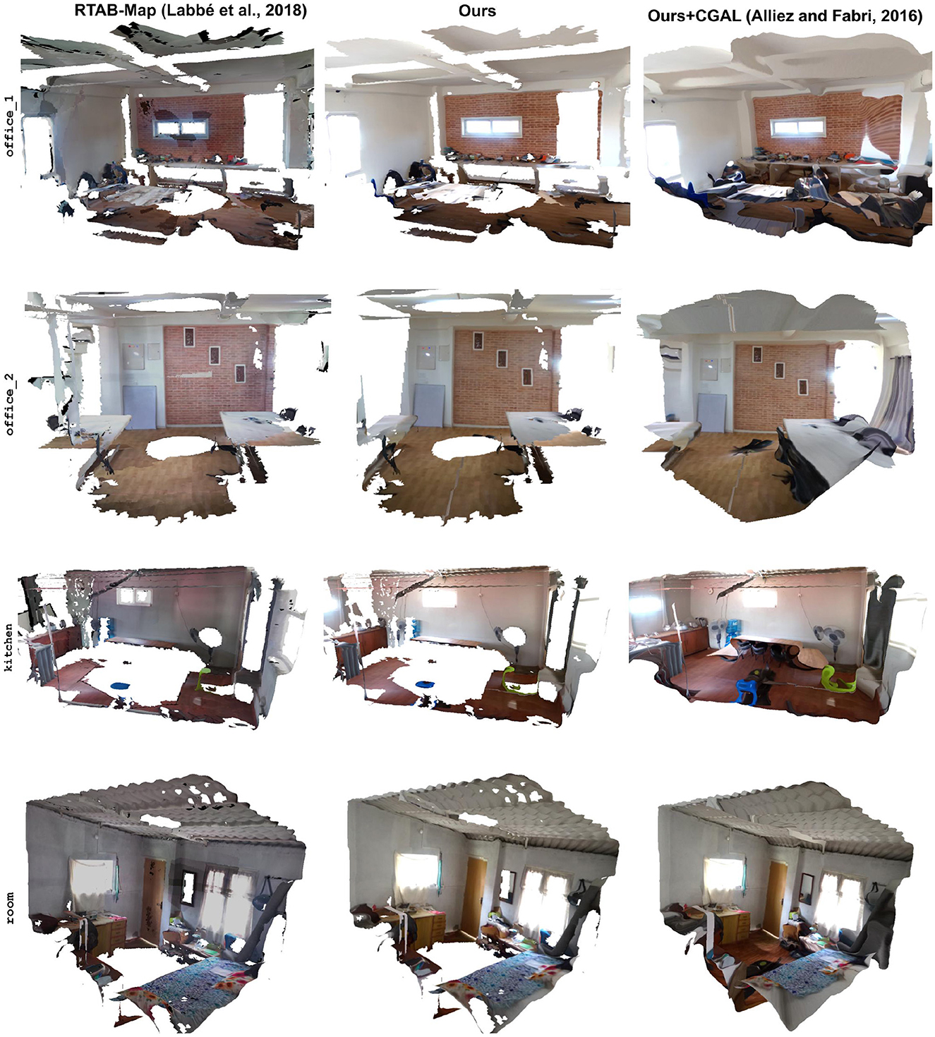
Figure A1. Textured meshes using different approaches: original 3D mesh (left), re-textured mesh (middle) with the proposed method, and hole-filled re-textured mesh (right).
Keywords: cubemap projection, least squares optimization, raytracing, texturing, 360 image alignment
Citation: Khanal B, Om M, Rijal S and Ojha VP (2024) Alignment of a 360° image with posed color images for locally accurate texturing of 3D mesh. Front. Comput. Sci. 6:1388174. doi: 10.3389/fcomp.2024.1388174
Received: 19 February 2024; Accepted: 27 August 2024;
Published: 19 September 2024.
Edited by:
Jon Sporring, University of Copenhagen, DenmarkReviewed by:
Maria Paula Queluz, University of Lisbon, PortugalDieter Fritsch, University of Stuttgart, Germany
Copyright © 2024 Khanal, Om, Rijal and Ojha. This is an open-access article distributed under the terms of the Creative Commons Attribution License (CC BY). The use, distribution or reproduction in other forums is permitted, provided the original author(s) and the copyright owner(s) are credited and that the original publication in this journal is cited, in accordance with accepted academic practice. No use, distribution or reproduction is permitted which does not comply with these terms.
*Correspondence: Sanjay Rijal, c2FuamF5LnJpamFsQGVrYmFuYS5pbmZv; Bishwash Khanal, YmlzaHdhc2gua2hhbmFsQGVrYmFuYS5pbmZv
†These authors have contributed equally to this work