 Agus Himawan1Andhika Sahadewa1,2*Masyhur Irsyam1Reguel Mikhail3Idwan Suhendra4Muchamad Rifai1,5Karsten Beckhaus6Yasin Widodo7,8Christian Moormann9Helmut F. Schweiger10Abi Maulana Hakim8,11Hasbullah Nawir1Fahmi Aldiamar12
- 1Bandung Institute of Technology, Bandung, Indonesia
- 2Indonesian Geotechnical Inztitute, Yogyakarta, Indonesia
- 3School of Civil and Environmental Engineering, Nanyang Technological University, Singapore, Singapore
- 4PT Hutama Karya, Jakarta, Indonesia
- 5PT Hutama Karya Infrastruktur, Jakarta, Indonesia
- 6BAUER Spezialtiefbau GmbH, Schrobenhausen, Germany
- 7PT Bauer Pratama Indonesia, Jakarta, Indonesia
- 8Razak Faculty of Technology and Informatics, Universiti Teknologi Malaysia, Kuala Lumpur, Malaysia
- 9Institute of Geotechnical Engineering, University of Stuttgart, Stuttgart, Germany
- 10Institute of Soil Mechanics, Foundation Engineering and Computational Geotechnics, Graz University of Technology, Graz, Austria
- 11Institut Teknologi Indonesia, Tangerang Selatan, Indonesia
- 12Implementation Unit for Geotechnic, Tunnel and Structure, Directorate General of Highway, Ministry of Public Works and Housing, Jakarta, Indonesia
Pile-supported embankments have been recognized as long-standing solutions for construction in compressible soft soils. Instead of improving the physical and mechanical properties of the soft soil, this method emphasizes efforts to transfer the embankment load to a competent layer below the compressible layer. Mortar column inclusion (inklusi kolom mortar or IKM) is recognized as one of the rigid inclusions in a pile-supported embankment. The IKM combined with a load transfer platform (LTP) has been widely utilized to support embankments. Studies on pile-supported embankments have generally focused on the arching mechanisms and geotextile tensile force evaluations; however, most of these investigations were conducted on soft cohesive soils. The application of pile-supported embankment on peat has rarely been studied comprehensively. This study presents a full-scale trial embankment on peat in West Sumatra, Indonesia. The 8-m-high trial embankment was supported by a series of IKM piles and a geotextile-reinforced LTP layer; instruments were then installed in the embankment, ground, LTP, geotextile, and IKM. These instruments included a series of vibrating wire earth pressure cells, vibrating wire strain gages, fiber optic sensors, vibrating wire piezometers, settlement profilers, settlement plates, and inclinometers. The instruments provided observations on the ground movements, IKM displacements, and stresses in the materials. Comprehensive evaluations from field monitoring allowed study of load transfer via the arching mechanism, deformation pattern, and IKM performance in peat. Finite element analyses (FEAs) were also conducted for comparison and verification. The field monitoring results and FEAs showed good agreement, thereby demonstrating the potential of the proposed ground improvement method for embankment construction on peat.
1 Introduction
Embankment works are generally considered as the most economical solutions in infrastructure construction involving roads, runways, and flood control embankments. Challenges often arise when embankments are situated along riverbanks, swamps, or other difficult areas. The soils in these zones are commonly characterized by thick and highly compressible soft soil deposits with low bearing capacities, including organic soil and peat. The common challenge in constructing an embankment on peat is to provide an alternative solution to the existing conventional methods. A structure with deep foundations may be the best solution for reducing long-term settlement; however, this demands a large budget, for which preloading and accelerated consolidation may be the most inexpensive solution. Unfortunately, this method requires significant construction time. In addition to consolidation, there are many uncertainties with regard to long-term settlement, which are attributed to secondary compression of the peat.
Recent studies on peat improvement methods have been reported by Axelsson et al. (2002), Black et al. (2007), Deboucha et al. (2008), Hashim and Islam (2008), Kazemian and Huat (2009), and Murugesan and Rajagopal (2009). Additionally, Fox and Edil (2000), Allgood et al. (2001), Wissmann et al. (2000), Winter et al. (2005), and Carchedi et al. (2006) have presented peat improvement methods for specific construction objectives, such as road embankments, railroads, and building structures. According to Huat et al. (2014), the aforementioned investigators reported that the various methods were successful in providing the required bearing capacities for the design loads. However, only the pile-supported solutions were observed to show minimal settlement over the years.
Pile-supported embankments have been broadly applied as construction solutions for compressible soils. In principle, this method does not improve the physical and mechanical properties of soft soils but entails transfer of the embankment load directly to a competent layer below the compressible layer via the piles. At a minimum, this method consists of a set of piles and a load transfer platform (LTP) layer that is commonly built using compacted granular materials. Through this method, most of the embankment load is transferred to the piles through the LTP via an arching mechanism. As only a small portion of the load is carried by the compressible soil between the piles, settlements can be reduced. The load concentration on the piles and consequent settlement reduction can be further optimized by reinforcing the LTP with high-tensile-strength geotextile layers. The geotextile components thus bear the embankment load between the piles and transfer it to the piles, leading to higher arching efficiency, larger load on the piles, and lower pressure on the soil between the piles, with consequent settlement reduction.
The performances of pile-supported embankments with geotextile-reinforced LTPs have been investigated by Hewlett and Randolph (1988), Low et al. (1994), Hong et al. (2007), Yun-min et al. (2008), van Eekelen et al. (2012a), van Eekelen et al. (2012b), Lu and Miao (2015), Briançon and Simon (2017), and Al-Naddaf et al. (2019). These studies have generally focused on soft cohesive soils, arching mechanisms, and geotextile tensile force evaluations. To the best of the authors’ knowledge, the performances of pile-supported embankments on highly organic soils and peat have not been investigated extensively thus far compared to those on soft cohesive soils.
Mortar column inclusion (inklusi kolom mortar or IKM) has gained popularity and become one of the most robust pile types in pile-supported embankments. IKM is a cast-in-place concrete mortar pile that is installed using a mobile rig equipped with a mortar injector and a displacement/continuous flight auger. Depending on the ground conditions, an IKM rig can achieve an installation productivity of up to 1,000 m a day.
2 Full-scale trial embankment
A full-scale trial embankment of approximately 140 m length and 50 m width was constructed as part of the Trans-Sumatera Toll Road Project in Padang Pariaman, West Sumatra, Indonesia. The map of peat distribution and carbon content in the region indicates that the project is situated on a hemic peat deposit (Wahyunto et al., 2003). The existence of peat in this location was further confirmed by soil investigations (Figure 1A). Peat and organic silt were observed up to a depth of 11 m below the surface. In detail, the uppermost soil layer extending to a depth of up to 7.5–8 m was composed of very soft organic peat; below this layer, a mixture of soft silt and organic materials was observed up to depth of 11 m. Figure 1B shows the typical hemic peat observed in the project area.

Figure 1. (A) Soil profile and (B) hemic peat at the project location.
A combined IKM and geotextile-reinforced LTP was selected for soil improvement in this project, which is a first-of-its-kind application of an improvement system on peat in Indonesia. Therefore, a full-scale trial embankment was constructed to evaluate the performance. The trial embankment was 8 m high from the top surface of the original soil (Figure 2A) and was supported by IKM piles of diameter 420 mm. These piles were installed in a 1.6 m × 1.6 m square configuration. The IKM length varies between 15 m and 17 m depending on the auger penetration refusal during installation. The six outermost piles around the toe of the slope were strengthened with steel reinforcement cages to increase the bending moment capacity. A pile cap of dimensions 0.5 m × 0.5 m × 0.2 m was installed on each IKM head, and a 1.5-m-thick granular LTP layer was constructed on the IKM piles. This LTP was reinforced using two layers of high-strength geotextiles having an ultimate tensile strength (Tult) of 1,600 kN/m. The geotextile reinforcements were laid out in both the transversal and longitudinal directions (Figure 2B). Figure 2C presents the detailed instrumentation layout plan. Figure 3 presents some photographs from the IKM construction work in the trial embankment area, and Figure 4 shows the installation of the high-strength geotextiles and LTP.
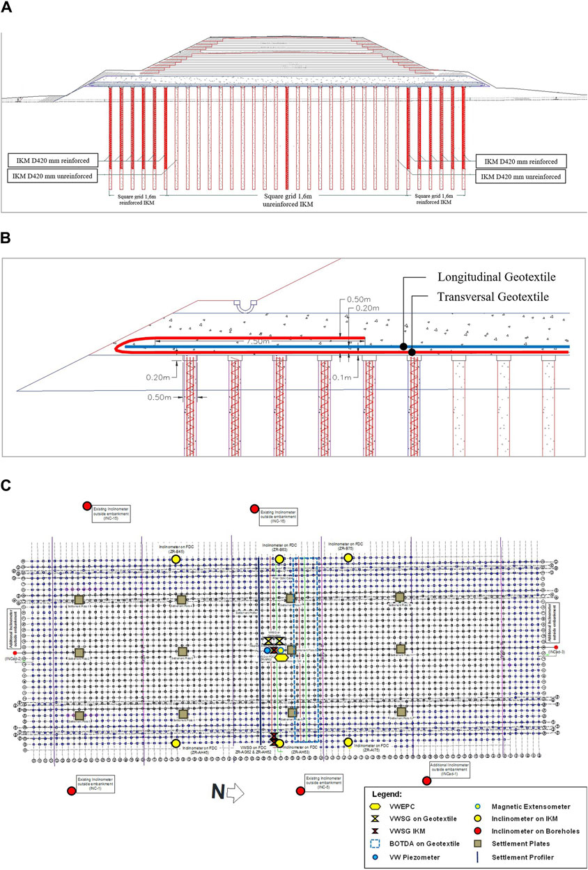
Figure 2. (A) Cross section of the trial embankment, (B) configuration of the high-strength geotextile, and (C) layout of the geotechnical instrumentation (source: PT Bauer Pratama Indonesia).
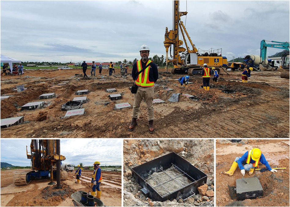
Figure 3. Construction of IKM piles in the trial embankment area (source: PT Bauer Pratama Indonesia).

Figure 4. Installation of the high-strength geotextile and construction of the LTP in the trial embankment area (source: PT Bauer Pratama Indonesia).
3 Field instrumentation and monitoring programs
A comprehensive field instrumentation program was set up to closely monitor the embankment construction and evaluate the ground improvement performance. A set of vibrating wire earth pressure cells (VWEPCs) of diameter 230 mm were installed on several of the pile caps and in the LTP to evaluate the stress distribution in the LTP (Figure 5A). Owing to reasons like including the readily available stock of VWEPCs in the market and limited project schedule, it was decided that the VWEPCs would be installed at the centers of the square pile caps. This arrangement may not allow exact measurements of the stresses on the pile caps as these stresses may not be uniform. The size difference between the VWEPC and pile cap may result in underestimated stress measurements. The measured stresses at the pile cap centers may be lower than the real applied stresses on the overall pile cap surfaces. For future research, installation of a set of VWEPCs to cover the entire surface of the pile cap is strongly recommended where the stress variability within the pile cap is of particular interest. Vibrating wire strain gage (VWSG) sensors were installed in selected IKMs and the geotextiles to measure the strains (Figures 5B–D). The strain on the geotextile was also measured using a Brillouin optical time-domain analysis (BOTDA) module (Figure 5E). Lateral deformations of the embankments and IKM piles were measured using inclinometers. A series of inclinometer cases were prepared around the embankments (at the boreholes) and IKMs. Figure 5F shows the inclinometer casing installation around the embankment perimeter. Figure 5G presents the casing preparation inside the IKM. Vibrating wire (VW) piezometers were also installed at three different depths to measure the excess pore water pressure below the center of the embankment. A settlement profiler was mounted on the pile cap to observe any settlement along the embankment base. Figures 6A–C show the settlement measurements using a profiler. The ground settlement was also measured using magnetic extensometers and settlement plates of dimensions 40 cm × 40 cm (Figures 6D–F).
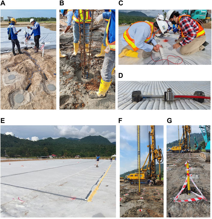
Figure 5. Installation of (A) VWEPCs in the IKMs, (B) VWSG sensors in the reinforced IKMs, (C, D) VWSG sensors on the geotextile layer, (E) BOTDA module on the geotextile, and (F, G) inclinometers (source: PT Bauer Pratama Indonesia).
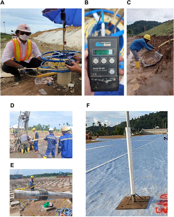
Figure 6. Installation of the (A–C) settlement profiler, (D, E) magnetic extensometer, and (F) settlement plate (source: PT Bauer Pratama Indonesia).
4 Numerical modeling
A series of finite element (FE) models was developed to study the load transfer mechanism of the ground improvement system. In this case, the stress distribution between the LTP layer and IKM piles via the arching mechanism, negative and positive resistances by the IKM shaft, and IKM tip resistance on the competent layer were evaluated. Three FE models were developed in this study using Plaxis, namely a 2D plane strain model of the entire embankment (Figure 7A), a 3D model of 1.6 m × 1.6 m tributary load area on a single IKM (Figure 7B), and a 3D-extruded model of half of the embankment (Figure 7C). The model boundary conditions at both sides were set to normally fixed, while the boundary conditions for the bottom and top surfaces were set to fully fixed and free, respectively.
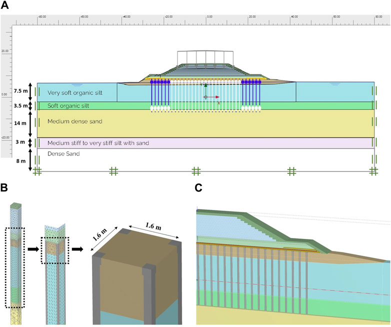
Figure 7. Plaxis results of the (A) 2D plane strain model of the trial embankment, (B) 3D model of a single IKM tributary load area, and (C) extruded half embankment.
The site investigation results, laboratory test data, and empirical correlations were evaluated thoroughly to choose the input soil parameters and constitutive models for the numerical analyses. The organic soil and peat layers extending from 0 m to 11.5 m were modeled with the soft soil creep (SSC) model, which is capable of modeling the primary and secondary compressions (i.e., creep) of the soft soil (Bentley, 2020a; Bentley, 2020b). Below the organic and peat layers, the 14-m-thick medium dense sand was modeled with the Mohr–Coulomb (MC) failure criterion. The hardening soil (HS) model was chosen for the following medium stiff silt, including the sand layers. Dense sand was observed at the end of boring during the field investigation. Detailed information on these constitutive models and the associated input parameters can be found in the Plaxis manual (Bentley, 2020a; Bentley, 2020b). The input soil parameters for this study are presented in Table 1.
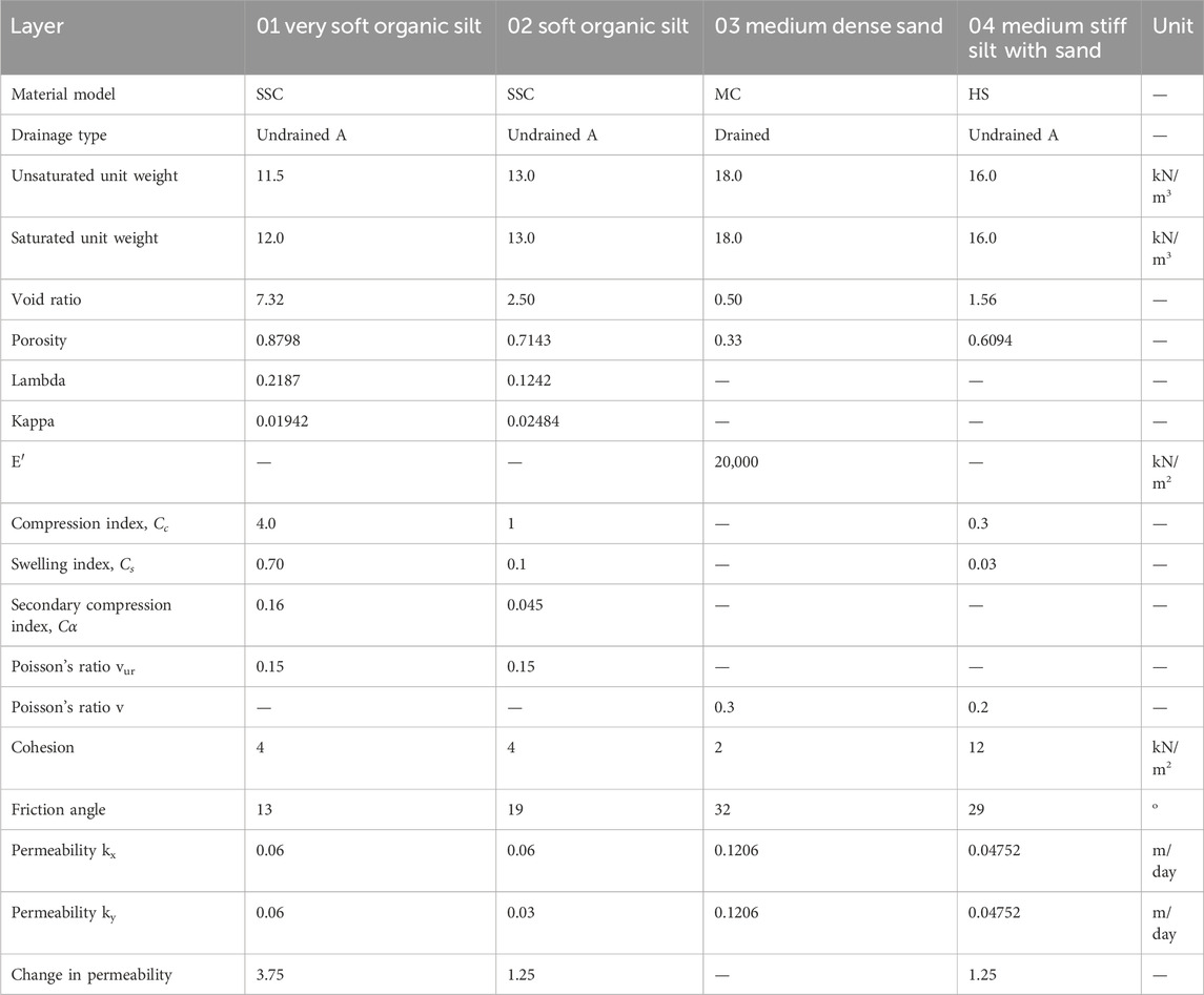
Table 1. Input soil parameters for the numerical model in Plaxis.
The geotextile with a high tensile strength of 1,600 kN/m used in the trial embankment was modeled as an elastoplastic anisotropic geogrid element; this element required two input parameters, namely stiffness and strength (Np). The stiffness is a function of the Young’s modulus (E) and cross-sectional area (A) of the geotextile. Considering that the strain of the geotextile should be maintained below 5% during road operations, the designed stiffness values along the strong axis (machine direction or MD) and weak axis (cross direction or CD) were 16,900 kN/m and 452 kN/m, respectively. The designed strength values along the MD and CD were 845 kN/m and 22.6 kN/m, respectively. Each IKM pile was modeled as an embedded beam row (EBR) element with E = 7.3 × 10⁶ kN/m2, as recommended by the ASIRI National Project (2012). The EBR is also known as embedded pile row (EPR). Sluis (2012) presented the EBR model development and its validation. When modeling piles in rows, the EBR offers more realistic pile–soil interaction behaviors than other classical methods, such as plates and node-to-node anchor methods. The EBR model requires several inputs, including the spacing between the row of piles in the out-of-plane direction, pile modulus elasticity, as well as axial and bending moment capacities. The bending moment capacities of unreinforced and reinforced IKM piles were set to 20 kN∙m and 70 kN∙m, respectively. The sequence of embankment construction, where each lift had a thickness of 40 cm, was considered in the numerical calculations. The compaction process for each lift was represented by the compacted unit weight of the embankment in the model.
5 Field monitoring results
The trial embankment construction commenced in February 2022. On 26 April 2022, the embankment reached its maximum height (Figure 8). The piezometers indicated that the peat layer experienced very little to negligible excess pore water pressure development (Figure 9A). Settlement profiler monitoring was conducted regularly from the first fill embankment placement to November 2022; this monitoring shows that the shape of the settlement trough was formed approximately 7 days after reaching the maximum height (Figure 9B). Thereafter, the settlement profiler showed a more uniform vertical deformation, indicating that the embankment settled as a rigid body. The total settlement values at the tip and center of the embankment were ±19.6 cm and ±31.9 cm, respectively. Figure 10A shows the settlement plate monitoring at the same interval as that of the settlement profiler. The embankment edge settled around 100–150 mm, whereas the middle of the embankment settled at about 200 mm. Similarly, the magnetic extensometer in the organic soil layer showed a relatively uniform vertical deformation of about 212 mm (Figure 10B).
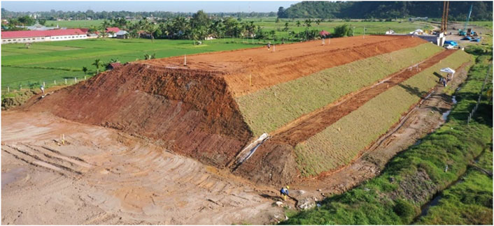
Figure 8. Trial embankment at the maximum height.
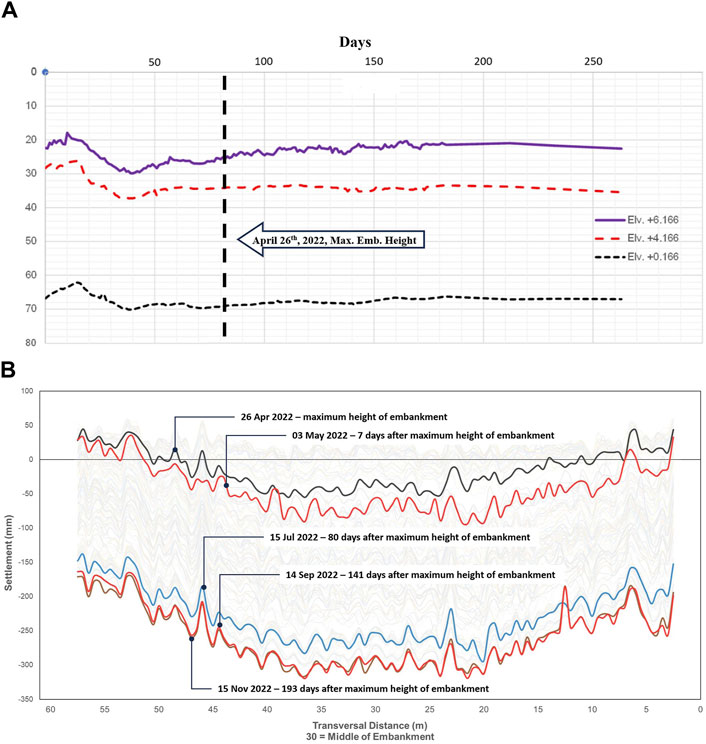
Figure 9. (A) Total pore water pressure and (B) settlement profiler readings from the trial embankment.
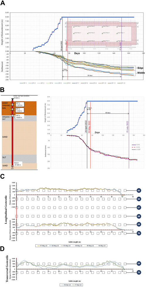
Figure 10. Trial embankment results from the (A) settlement plate, (B) extensometer, and (C, D) BOTDA geotextile strain.
The BOTDA measurements of the geotextile strains in the longitudinal and transversal directions showed the largest tensile strains of 1,161 µε and 1,269 µε, respectively (Figures 10C, D). These values were different from the VWSG measurements. The largest tensile strains along the longitudinal and transversal directions based on the VWSG were 2,017 με and 657 με, respectively. The differences in these results between the BOTDA and VWSG may be attributed to the exact placement of these sensors. The VWSG was placed in the middle of the embankment, where the geotextile at this location did not experience the maximum tensile force during loading. Accordingly, the VWSG measurement in the transversal direction was around half of that of the BOTDA measurement. Additionally, the differences in the placements of the BOTDA and VWSG sensors showed differences in other parameters, including the soft soil thickness and IKM length. Hence, these variations were responsible for the differences in the tensile strain measurements from the two sensors. Nevertheless, the main intention of installing these sensors was to ensure that the geotextile strain did not exceed the allowable strain of 5% or 50,000 με; this was considered as a crucial factor because the installation of the high-strength geotextile was primarily to provide additional horizontal stiffness to the LTP above the peat, thereby reducing the lateral deformations and bending moments of the IKMs around the slope area. For future research concerning the geotextile efficiency, it is recommended to select locations as well as the BOTDA and VWSG sensor layouts in a manner that allows measurement of the maximum strain and its relationship to the differential settlement around the IKM piles. Thus, comprehensive comparisons can be made between the performances of the BOTDA and VSWG for the geotextile strain measurements.
Three pairs of VWEPCs were mounted at two elevations, namely +8.20 (at the base of the LTP) and +8.95 (at the middle of the LTP), as shown in Figure 11A. The results of the VWEPC readings located on top of the IKM and in the middle of the LTP showed maximum pressures of 531.8 kPa (Figure 11B) and 242.2 kPa (Figure 11C), respectively. The two VWEPCs placed between the columns at the LTP base showed pressures ranging from 37.6 kPa to 50.6 kPa; their counterparts at the higher elevation experienced larger pressures ranging from 74.9 kPa to 121.6 kPa.
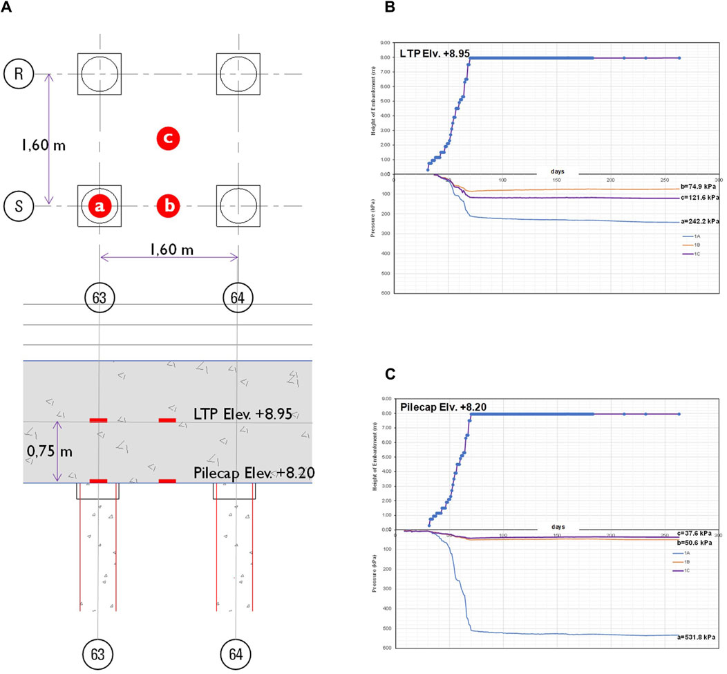
Figure 11. Vibrating wire earth pressure cells (VWEPCs): (A) layout and (B, C) readings at two locations.
6 Load transfer mechanism in the trial embankment
The load transfer mechanism in the pile-supported embankment is one of the most crucial observations of this study. Theoretically, the embankment load is delivered to the LTP and is subsequently transferred to the IKM piles. Between the piles, the load is received by the LTP with the high-strength geotextile layers. This load leads to the development of strain and tensile forces in the geotextile, which eventually compress the IKMs. This study showed that the peat below the embankment did not bear any significant load, as expected. Most of the embankment load was transferred to the IKM piles, which was confirmed by the measurements from the piezometers in the peat layer (Figure 9A). The observed pore water pressures at three different depths increased by only 2–10 kPa after reaching the final embankment load. Figure 9A also demonstrates the fast excess pore water pressure dissipation since peat has a much higher permeability than clay. Given that the peat layer has a water content of 413%–630% and moisture unit weight of 9.5 kN/m3, the excess pore water pressure dissipation may not be followed by increase in the effective stress, as the peat behaves like water.
The load transfer mechanism was also verified using the earth pressure cells mounted on the IKMs. Figure 11 shows that the IKM heads experience the highest pressures, whereas the smallest values are located between the IKMs. The numerical results showed consistent patterns with the field measurements, which were slightly lower than the values obtained with the pressure cells. The FE modeling showed that the maximum stress of 587.3 kPa was located at the IKM head (Figure 12A), where a pressure of 267.6 kPa occurred in the middle of the LTP above the IKM head. Stresses between the IKM piles at the base of the LTP and the middle of the LTP were as low as 50.23 kPa and 103.0 kPa, respectively. The load transfer mechanism and principal stress rotation based on the 3D FE analysis are shown in Figure 12B.
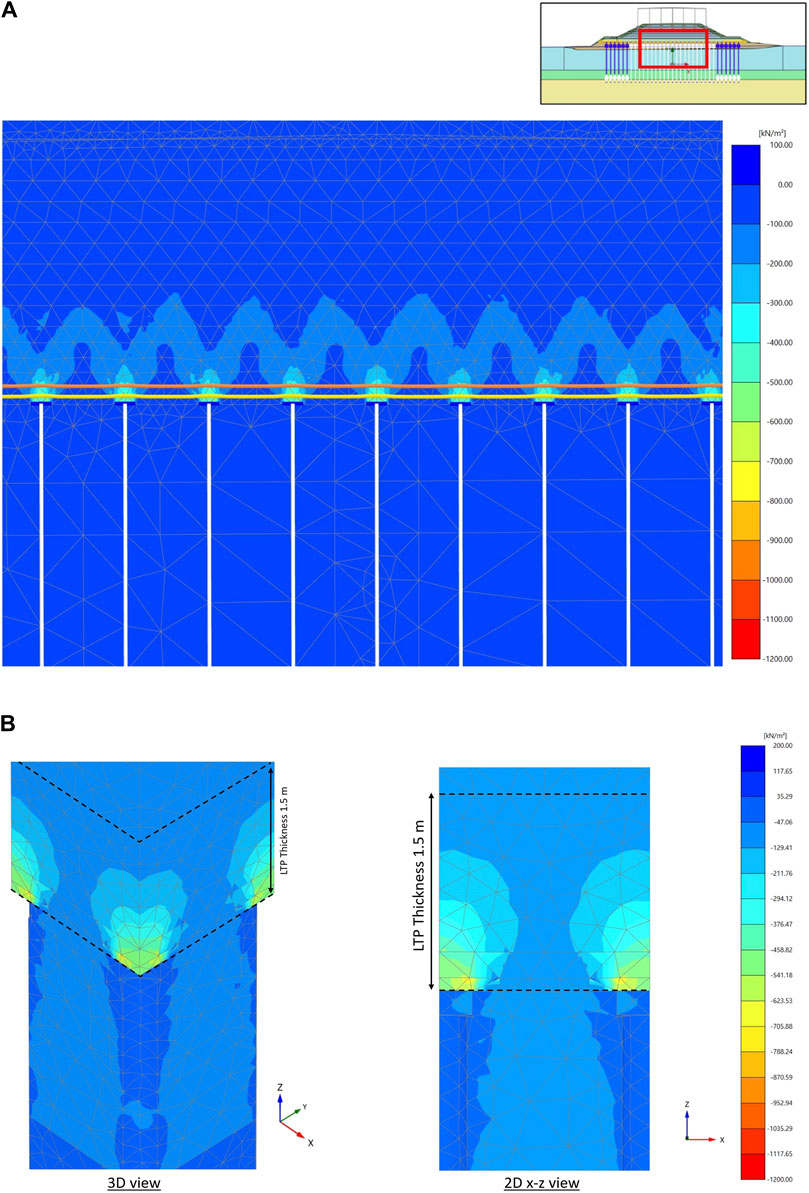
Figure 12. Principal effective stress directions of the numerical model after consolidation in the (A) 2D and (B) 3D views.
The peat layer experienced a long-term settlement despite bearing only a minor load, as indicated in Figures 9B, 10. In fact, this settlement could be attributed to the consolidation in the medium stiff silt layer located directly below the 15-m-thick medium dense layer (Figure 1). The embankment load that was transferred by the IKM piles to the deeper layers led to stress and excess pore water pressure developments in these layers, including the silt layer. As the excess pore water pressure dissipated, a corresponding settlement occurred over time. Although no field instruments were installed in the deep layers, consolidation in the silt layer was clearly observed in the FE analysis (Figure 13). The FE analysis also showed that the layers above the consolidated silt layer experienced rigid body motion settlement, which was consistent with the results of the settlement profiler (Figure 9B). In addition, the FE analysis showed a total long-term vertical displacement as large as 344.2 mm at the middle of the embankment (Figure 14); this value is similar to that observed during field monitoring. However, the distribution of the actual settlement is more uniform compared to that obtained by FE modeling. These differences in uniformity may be the result of embankment rigidity or variation in peat compressibility. A stability analysis was also conducted using 2D FE analysis. The global safety factor (SF) of the trial embankment was as high as 1.69 (Figure 15), which corresponded to the critical failure plane located at the unimproved area around the embankment edge. Consequently, the SF of the improved embankment slope should be higher.
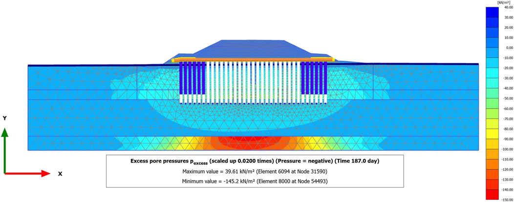
Figure 13. Excess pore water pressure in the medium stiff silt and sand layer due to the embankment.
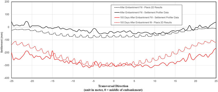
Figure 14. Total displacement below the embankment based on data from the settlement profiler and 2D numerical model after consolidation.
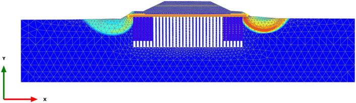
Figure 15. Plaxis 2D global stability analysis result of the trial embankment (SF = 1.69).
7 Conclusion
Mortar column inclusion and LTP have been widely used in pile-supported embankments. Many of the extant studies on pile-supported embankments were focused on soft soils, with very few studies being conducted of pile-supported embankments on peat. This work reports the performance of an 8-m-high full-scale trial embankment on peat supported by IKM piles and a geotextile-reinforced LTP. A set of instruments embedded in the embankment system allowed comprehensive study of the load transfer mechanism, deformation pattern, and performance of the IKM in peat. FE analyses were carried out for comparison and verification of the field observation results.
The present study suggests that arching in the LTP is a crucial factor in the load transfer mechanism. The VWEPC results explain the stress distribution in the LTP; the IKM heads experienced the largest stress values, whereas the LTP base between the IKM piles experienced the lowest stress values. This variation suggested an arch-like stress distribution in the LTP. The area between the IKM piles was also supported with a high-strength geotextile. Tensile strains occurred in the geotextile, suggesting that the geotextile also contributed toward bearing the embankment load between the IKM piles. Owing to the arching mechanism and the presence of the geotextile, the surface near the peat layer between the IKM piles only experiences a very small portion of the load. This load sharing mechanism contributed to significant settlement reduction, which was further supported by the FEM results.
The field observations indicated that the embankment load was successfully transferred to the deeper layers; this finding was strongly supported by the piezometer readings. The soft organic and peat layers experienced insignificant pore water pressure increments. The settlement observed during field monitoring did not originate from these soft layers and was instead associated with the medium stiff layer situated at a depth of 10 m from the IKM tip. The FE results were also consistent with this finding.
The combined IKM and geotextile-reinforced LTP demonstrated satisfactory performance in supporting the embankment on peat. Thus, we successfully identified the load transfer mechanism and ground deformation in the embankment system through this study. No further ground movements were observed in the trial embankment. The field monitoring and FE results were consistent and in good agreement. However, the actual settlement observed displayed a more rigid behavior. This comprehensive study proves that the combination of IKM piles and geotextile-reinforced LTP can be a viable and promising alternative to the conventional solution for embankment construction on peat.
Data availability statement
The raw data supporting the conclusions of this article will be made available by the authors without undue reservation.
Ethics statement
Written informed consent was obtained from all concerned individuals for the publication of any potentially identifiable images or data included in this article.
Author contributions
AH: Conceptualization, Formal analysis, Methodology, Software, Visualization, Writing–original draft, Writing–review and editing. AS: Conceptualization, Visualization, Writing–original draft, Writing–review and editing. MI: Conceptualization, Supervision, Visualization, Writing–original draft. RM: Visualization, Writing–original draft, Writing–review and editing. IS: Resources, Writing–review and editing. MR: Resources, Writing–review and editing. KB: Writing–review and editing. YW: Project administration, Resources, Writing–review and editing. CM: Writing–review and editing. HS: Software, Writing–review and editing. AMH: Writing–review and editing. HN: Writing–review and editing. FA: Writing–review and editing.
Funding
The authors declare that financial support was received for the research, authorship, and/or publication of this article. The authors declare that this field work was financially supported by PT Hutama Karya, PT Hutama Karya Infrastruktur, and PT Bauer Pratama Indonesia. The funding for publication and numerical modeling license was provided by the FTSL ITB–P2MI Research Grant.
Acknowledgments
This work is based on a trial embankment proof test in the Trans-Sumatera Toll Road Project, Indonesia. The authors would like to thank the teams from PT Hutama Karya, PT Hutama Karya Infrastruktur, and PT Bauer Pratama Indonesia for support with the field instrumentation and monitoring. The authors also wish to express their gratitude for the FTSL ITB–P2MI Research Grant from Bandung Institute of Technology. The authors also express their sincere appreciations for the funding support.
Conflict of interest
Author IS was employed by PT Hutama Karya. Author MR was employed by PT Hutama Karya Infrastruktur. Author KB was employed by BAUER Spezialtiefbau GmbH. Author YW was employed by PT Bauer Pratama Indonesia.
The remaining authors declare that the research was conducted in the absence of any commercial or financial relationships that could be construed as a potential conflict of interest.
Publisher’s note
All claims expressed in this article are solely those of the authors and do not necessarily represent those of their affiliated organizations or those of the publisher, editors, and reviewers. Any product that may be evaluated in this article or claim that may be made by its manufacturer is not guaranteed or endorsed by the publisher.
Author disclaimer
All opinions, findings, conclusions, and recommendations presented in this paper are those of the authors and do not necessarily reflect the views of any supporting institutions.
References
Allgood, C., Weppler, L., Lien, B., and Fox, N. S. (2001). Geo-pier® intermediate foundation systems—case studies for building foundations over soft organic soils and peat, in Proceedings of International Conference on Problematic Soils, Nottingham, UK, July 29–30, 2003. Singapore: CI-Premier Pte Ltd.
Al-Naddaf, M., Han, J., Xu, C., Jawad, S., and Abdulrasool, G. (2019). Experimental investigation of soil arching mobilization and degradation under localized surface loading. J. Geotechnical Geoenvironmental Eng. 145 (12), 04019114. doi:10.1061/(asce)gt.1943-5606.0002190
ASIRI National Project (2012). Recommendations for the design, construction and control of rigid inclusion ground improvements. Paris, France: Presses des Ponts.
Axelsson, K., Johansson, S.-E., Andersson, R., and Djupstabilisering, S. (2002). Stabilization of organic soils by cement and puzzolanic reactions-feasibility study. Linkoping, Sweden: Swedish Deep Stabilization Research Centre
Bentley (2020a). PLAXIS 2D-material models manual. Dublin, Ireland: Bentley Systems International Limited.
Bentley (2020b). PLAXIS 3D-material models manual. Dublin, Ireland: Bentley Systems International Limited
Black, J., Sivakumar, V., Madhav, M., and Hamill, G. (2007). Reinforced stone columns in weak deposits: laboratory model study. J. Geotechnical Geoenvironmental Eng. 133, 1154–1161. doi:10.1061/ASCE1090-02412007133:91154
Briançon, L., and Simon, B. (2017). Pile-supported embankment over soft soil for south Europe atlantic high speed line. Geosynth. Int. 24 (3), 293–305. doi:10.1680/jgein.17.00002
Carchedi, D. R., Monaghan, J., and Parra, J. (2006). Innovative stabilization of peat soils for railroad foundation using rammed aggregate piers, ground modification and seismic mitigation. ASCE, Virginia, USA: Geotechnical Special Publication. No. 152, 127–134.
Deboucha, S., Hashim, R., and Alwi, A. (2008). Engineering properties of stabilized tropical peat soils. Electron. J. Geotechnical Eng. 13, 1–9.
Fox, N. S., and Edil, T. B. (2000). Case histories of rammed aggregate pier soil reinforcement construction over peat and highly organic soils. Soft Ground Technol., 146–157. doi:10.1061/40552(301)12
Hashim, R., and Islam, M. S. (2008). Properties of stabilized peat by soil-cement column method. Electron. J. Geotechnical Eng. 13-J, 1–9.
Hong, P. W., Lee, J. H., and Lee, K. W. (2007). Load transfer by soil arching in pile-supported embankments. Jpn. Geotech. Soc. 47 (Soils and Foundations), 833–843. doi:10.3208/sandf.47.833
Huat, B. B. K., Prasad, A., Asadi, A., and Kazemian, S. (2014). Geotechnics of organic soils and peats. London, UK: CRC Press.
Kazemian, S., and Huat, B. B. K. (2009). Compressibility characteristics of fibrous tropical peat reinforced with cement column. Electron. J. Geotechnical Eng. 14-C, 1–13.
Low, B. K., Tang, S. K., and Choa, V. (1994). Arching in piled embankments. J. Geotechnical Eng. 120, 1917–1938. doi:10.1061/(asce)0733-9410(1994)120:11(1917)
Lu, W., and Miao, L. (2015). A simplified 2-D evaluation method of the arching effect for geosynthetic-reinforced and pile-supported embankments. Comput. Geotechnics 65, 97–103. doi:10.1016/j.compgeo.2014.11.014
Murugesan, S., and Rajagopal, K. (2009). Studies on the behavior of single and group of geosynthetic encased stone columns. J. Geotechnical Geoenvironmental Eng. © ASCE 136 (1), 129–139. doi:10.1061/ASCEGT.1943-5606.0000187
Sluis, J. J. M. (2012). Validation of embedded pile row in PLAXIS 2D. Master of Science thesis. Delft, Netherlands. : Delft University of Technology.
van Eekelen, S. J. M., Bezuijen, A., Lodder, H. J., and van Tol, A. F. (2012a). Model experiments on piled embankments Part II. Geotext. Geomembranes 32, 82–94. doi:10.1016/j.geotexmem.2011.11.003
van Eekelen, S. J. M., Bezuijen, A., Lodder, H. J., and van Tol, A. F. (2012b). Model experiments on piled embankments Part I. Geotext. Geomembranes 32, 69–81. doi:10.1016/j.geotexmem.2011.11.002
Wahyunto, , Ritung, S., and Subagjo, H. (2003). Peta luas sebaran lahan gambut dan kandungan karbon, Wetlands International—Indonesia Programme and Wildlife Habitat Canada. Bogor, Indonesia: Text in Indonesian.
Winter, M., Johnson, P., and Reid, J. (2005). “Construction of road foundations on soft ground using lightweight tire bales,” in Proceedings of International Conference on Problematic Soils, , Famagusta, North Cyprus, May 25–27, 2005 (North Cyprus: Eastern Mediterranean University Press). 25–27.
Wissmann, K. J., Fox, N. S., and Martin, J. P. (2000). Rammed aggregate piers defeat 75-foot long driven piles. Perform. Confirmation Constr. Geotechnical Facil., 198–211. doi:10.1061/40486(300)12
Keywords: embankment, mortar column inclusion, inclusi kolom mortar (IKM), geotextile, peat
Citation: Himawan A, Sahadewa A, Irsyam M, Mikhail R, Suhendra I, Rifai M, Beckhaus K, Widodo Y, Moormann C, Schweiger HF, Hakim AM, Nawir H and Aldiamar F (2024) Full-scale trial embankment and numerical analysis of mortar column inclusion and high-strength geotextile-reinforced load transfer platform on peat. Front. Built Environ. 10:1379851. doi: 10.3389/fbuil.2024.1379851
Received: 06 February 2024; Accepted: 30 July 2024;
Published: 22 August 2024.
Edited by:
Prabir K. Kolay, Southern Illinois University Carbondale, United StatesReviewed by:
Laurent Briançon, Institut National des Sciences Appliquées de Lyon (INSA Lyon), FranceVishwas Sawant, Indian Institute of Technology Roorkee, India
Copyright © 2024 Himawan, Sahadewa, Irsyam, Mikhail, Suhendra, Rifai, Beckhaus, Widodo, Moormann, Schweiger, Hakim, Nawir and Aldiamar. This is an open-access article distributed under the terms of the Creative Commons Attribution License (CC BY). The use, distribution or reproduction in other forums is permitted, provided the original author(s) and the copyright owner(s) are credited and that the original publication in this journal is cited, in accordance with accepted academic practice. No use, distribution or reproduction is permitted which does not comply with these terms.
*Correspondence: Andhika Sahadewa, sahadewa@itb.ac.id