 Rabii Slimane1
95% of researchers rate our articles as excellent or good
Learn more about the work of our research integrity team to safeguard the quality of each article we publish.
Find out more
ORIGINAL RESEARCH article
Front. Acoust. , 07 November 2023
Sec. Acoustic Materials, Noise Control and Sound Perception
Volume 1 - 2023 | https://doi.org/10.3389/facou.2023.1277431
In a vehicle, the operation of mechanical systems generates undesirable vibrations and noise, and their reduction requires the study of three parts: vibrating systems, receiving structures, and connecting interfaces. The study presented in this paper concerns the connecting interfaces between subsystems. In particular, the in situ characterization of the isolation interface between two substructures by measuring dynamic transfer stiffness. In contrast to current methods, which require the disassembly of the vibration isolator from its original assembly, in situ methods have been studied and validated. This study sheds light on the strengths and limitations of each approach. These are known as the direct in situ method (D-IS) and round trip in situ method (RT-IS). Experimental validation has been carried out by comparing the D-IS method to the resonance method on a simple system. Good agreement is obtained between the two methods, making it possible to validate the method at low frequencies. Then, a comparison between the two methods D-IS and RT-IS is carried out on a more resonant test bench. The obtained stiffnesses were further validated using transfer path analysis (TPA) techniques to verify the performance of the proposed methods, and it was used to predict the response of another system, showing thus the independent nature of the identified dynamic stiffness.
Vibrations in a vehicle can be caused by various factors, and understanding the different types of vibrations and their possible causes is important for vehicle maintenance and safety. In a vehicle, vibration sources can be aerodynamic (wind), mechanical (engine transmission) or even electrical. Once generated, these vibrations are transmitted through various transfer paths and acoustically radiated inside the passenger compartment. It's important to note that while some vibrations may be minor and benign, others can indicate significant issues that require immediate attention. Ignoring vibrations in the vehicle can lead to further damage, reduced safety, and increased repair costs.
Vibration transfer path refers to the pathway through which vibrations are transmitted from one component or part of a system to another. Identifying and managing the vibration transfer path is crucial in various fields (automotive engineering, structural engineering, and machinery design). The noise is qualified as structure-borne-noise (SBN) if the transfer paths are structural. Otherwise, the transfer paths are airborne, and the noise is qualified as airborne noise. Unwanted vibrations can be mitigated by improving the characterization and design of the mechanical systems responsible for these vibrations, the receiving structures, and the isolation interfaces connecting them. By understanding and carefully managing the vibration transfer path, engineers can minimize the transfer of engine and road vibrations to the vehicle’s cabin, and optimize the performance, safety, and comfort of various systems and structures.
The field interested in the study and the modification of the vibroacoustic behavior of the vehicles is called Noise, Vibration, and Harshness (NVH). Characterizing the dynamic transfer stiffness is a critical step in designing effective vibration isolation systems, especially in applications where minimizing vibrations is essential for equipment performance, structural integrity, or human comfort. Acoustic radiation can reduce the ability to communicate between the crew members and affect the comfort of the passengers. Noise pollution also has a negative impact on human health. Indeed, it can cause physical and psychological disorders (Stansfeld and Matheson, 2003; Basner et al., 2014) such as fatigue, nervousness, stress, insomnia, lack of concentration, memory problems and social behavior problems (Ingle et al., 2005).
In the aeronautics industry, international standards are increasingly demanding in this regard. Therefore, to better understand and reduce these undesirable noises, aircraft manufacturers are increasingly paying considerable attention to the characterization and design of the mechanical systems responsible for vibrations, receiving structures and isolation interfaces that connect them. In this context this study has as objective to investigate and validate experimentally a method for in situ identification of the dynamic transfer stiffness characterizing the isolation interface between two substructures. This parameter helps engineers understand how vibrations are transmitted from one substructure to another and allows for the optimization of isolation systems.
Dynamic transfer stiffness is typically determined through experimental testing or numerical simulations. Experimental methods involve applying known forces or displacements at the interface and measuring the resulting forces or displacements on the other side to calculate the dynamic transfer stiffness. Engineers use this parameter to design and evaluate isolation systems, ensuring that vibrations generated by machinery or external forces do not adversely affect sensitive equipment, structures, or occupants. This study seeks to address the following question: can we robustly and practically identify the in situ dynamic transfer stiffness of the interface between two structures? The aim is to study and validate experimentally the direct in situ method and the round trip in situ method for determining dynamic transfer stiffness. Those methods are used for measurements, observations, or analyses that are conducted directly at the location or in the natural environment where the subject of study exists. They are valuable because they allow engineers to obtain data that is representative of the actual conditions, reducing the potential for modification during transport to a laboratory. These methods are particularly useful when it is impractical or impossible to remove the subject from its natural position. In order to test the performance of the two methods, an experimental validation using transfer path analysis approaches is carried out. First, a mass-isolator-mass system is used to validate the direct method by comparing it to the resonance method. Then, more realistic mass/beam/plate-isolator-plate test bench are constructed to further test and validate the methods on more resonant structures. The results showed that the identified stiffness is indeed a system-independent quantity and can be used to predict the response of a system with considerable accuracy.
In the following, Section 2 reviews the literature presenting the main existing methods of «identification of dynamic stiffness» and the « transfer path analysis (TPA) methods» used for validation. Section 3 is a presentation of the experimental studies carried out and a summary of the results obtained. Finally, a conclusion presents the main takeaways of this study.
This section presents a literature review focusing on the main methods of dynamic stiffness identification. Then the main transfer path analysis methods are presented with their advantages and limits.
The potential advantages of the direct in situ method include the simultaneous determination of dynamic stiffness components over a wide frequency range and without the need for test rigs (Meggitt et al., 2015; Meggitt, 2017; PATIL, 2019). To better understand the principle of this method, consider the system mentioned in Figure 1, where subsystem I can be composed of several isolators.
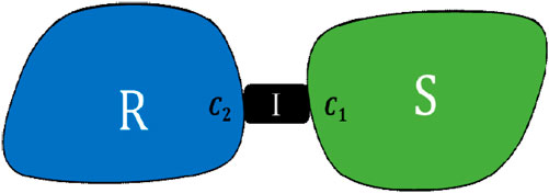
FIGURE 1. General system source-isolator-receiver.
To describe the transmission of vibrational energy through the isolator, the dynamic transfer stiffness is used, denoted by
Where the exponent is used to designate the substructure to which the quantity belongs, and the indices represent the position on the substructure. For example,
If each side of the isolator can move along 6 degrees of freedom (DOF), and neglecting nonlinearity, the dynamic transfer stiffness is entirely described by the following 6 × 6 matrix:
A complete description of the isolator should also include the dynamic stiffness matrices,
Where
In (HOGAN, 1988; Meggitt et al., 2015; van der Seijs et al., 2016), it is shown that the dynamic transfer impedance of an isolator I can be determined from the inverse of the coupled interface admittance matrix:
This allows the isolator to be characterized while coupled with its original assembly. The direct in situ method D-IS consists of directly measuring the interface admittance matrix of the coupled system. This method assumes that the interface points,
The significant problem in directly measuring the interface admittance matrix of the coupled system is the access to the required connection points
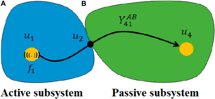
FIGURE 2. Dynamic system composed of an active subsystem (A) and passive subsystem (B).
In (Moorhouse et al., 2011; MEYER et al., 2016), it has been shown that the interface admittance matrix of the coupled system can be determined from a set of coupled transfer admittances, none of which require excitation at the interface point
This method is referred to by Round Trip In-Situ (RT-IS) (SOMERS, 2005; Moorhouse and Elliott, 2013; WIENEN et al., 2021).
Transfer path analysis (TPA) methods refer to engineering methods, based on tests and/or simulations, that make it possible to study the transfer of vibroacoustic energy from active components through transfer paths, airborne or structure-borne, to the connected passive substructures (DUBBAKA et al., 2003; DIEZ-IBARBIA et al., 2017). The purpose is to reduce certain types of unwanted noise/vibration to improve comfort, and the product lifecycle, guarantee the safety or even preserve stealth (VAN DER AUWERAER et al., 2007; YOSHIDA et al., 2013).
TPA is beneficial when the vibrating mechanisms are too complex to be modeled or directly characterized (De Sitter et al., 2010; Patil et al., 2015). TPA can be applied upstream of isolation interface characterization methods to detect dominant transfer paths. We can then anticipate this by making modifications to the isolation interface. TPA can also be applied downstream of isolation interface characterization methods using the identified stiffness to predict the vibration. In recent years, thanks to technological advances in data acquisition systems, several works have been increasingly interested in TPA methods (Elliott et al., 2013). The reference article (PATIL, 2019) presents a unified framework for classifying a wide range of TPA methods.
To understand the principle of the TPA methods, let us consider the dynamic system AB described in Figure 2. Subsystems A and B represent the active and passive parts of the assembly. Point 2 represents the interface which connects them, and point 1 represents the source of the vibrations. Identifying the excitation force at point 1 is impossible or impractical. TPA methods assume that the dynamic response at interface point 2 is measurable and can represent the source of excitation (Plunt, 2005; JANSSENS et al., 2011).
The response of target point 4 can be reconstructed from a specific description of the vibrations measured at the interface 2 and an appropriate set of frequency response functions (FRFs) linking these vibrations at the point of reception. Frequency response functions are either admittances (u represent displacements), mobilities (u represent velocities), or accelerances (u represent accelerations). This depends on the nature of the numerical or experimental measurements carried out, and the nature of the data extracted (displacement, velocity or acceleration). In the remainder of this article, we assume that u and Y represent displacements and admittances, respectively. The two most used families of transfer path analysis methods are classical and component-based. These two families will be presented in the following sections.
In the classical transfer path analysis family, the experimental measurements are performed on the coupled system AB to obtain the interface blocked forces (
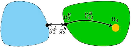
FIGURE 3. Classical TPA—Application of blocked forces.
To reconstruct the responses of the target points, one must apply these interface forces to the admittance of the decoupled subsystem B, as mentioned in the following equation:
Several methods of classical transfer path analysis are defined and used according to how the blocked forces (
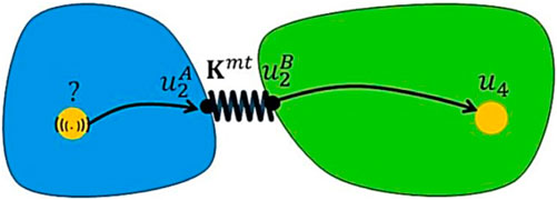
FIGURE 4. Classical TPA—mount stiffness.
The accuracy of this method depends strongly on the stiffness terms
This section presents an experimental comparison of the Direct In-Situ (D-IS) and round trip in situ (RT-IS) methods. Firstly, the validation was carried out using three configurations: i) a mass-isolator-mass (M-I-M) system, ii) a plate-isolator-plate (P-I-P) system and iii) a beam-isolator-plate (B-I-P) system. The first is used to identify the stiffness of the isolator suing the D-IS method, the second to identify the same stiffness using the RT-IS method and the third to compare to the accuracy of the identified stiffnesses using a third and independent coupled system. The isolator was connected via its four bolts, it is thus used everywhere to allow for comparison of the methods and verifies the transferability of the identified dynamic stiffness from one test bench to another. The used isolator is part of the HT2 series as described in Figure 5, manufactured by Parker Hannifin. The family of this isolator is known for its capability to provide very good control of all vibrations (Aerospace & Defense Isolator Catalog/Vibration, 2017).
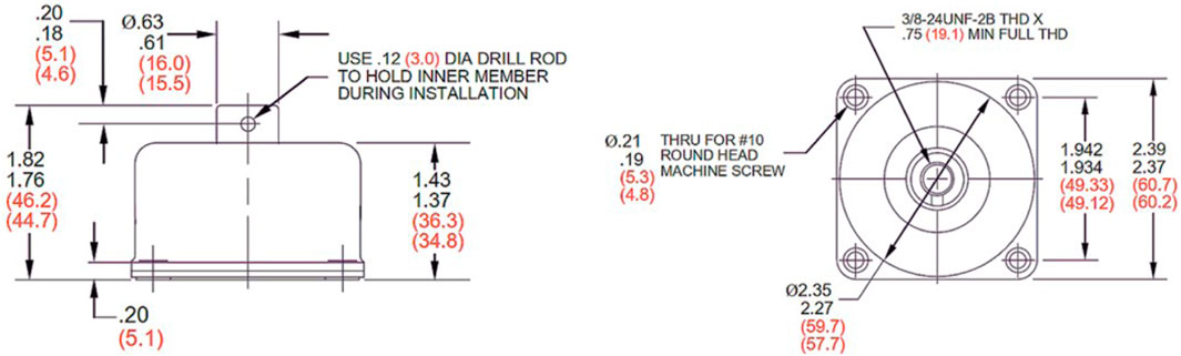
FIGURE 5. HT2 Series part dimensions (reproduced from Aerospace & Defense Isolator Catalog/Vibration, 2017 with permission from LORD Corporation).
Photos of the used test benches are presented in Figure 6. The geometrical and mechanical properties of the three systems are:
✓ System #1: (M-I-M)
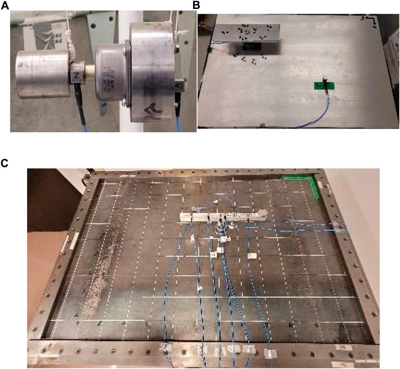
FIGURE 6. Photos of the used test benches (A) M-I-M (B) P-I-P (C) B-I-P.
Source mass 769.5 g—Isolator—Receiver mass 2,266.4 g.
✓ System #2: (P-I-P)
Source plate (Alu.) 20 cm × 6 cm × 1 cm—Isolator—Receiver plate (Alu.) 60 cm × 40 cm × 1 cm.
✓ System #3: (B-I-P)
Beam (Alu.) 40 cm × 2.55 cm × 2.55 cm - Isolator - Plate (Steel) 132.4 cm × 917 cm × 0.48 cm
This experimental study aims to identify the in situ dynamic stiffness of a simple Mass-Isolator-Mass system, as shown in Figure 7, with the D-IS method. Two triaxial accelerometers were used on either side of the isolator to directly measure the admittance matrix Y. Then a set of 3 forces (according to Tx, Ty, and Tz) were applied at each connection point
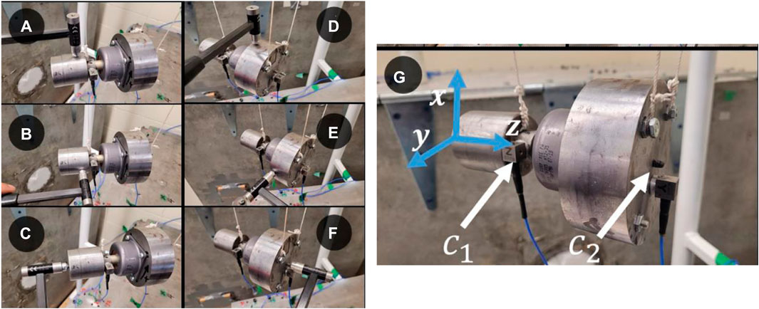
FIGURE 7. D-IS method, forces applied along the X-axis (A,D), Y-axis (B,E) and Z-axis (C,F) at each connection point
Figure 8 shows the dynamic stiffness obtained via the D-IS method according to Dofs Tx, Ty, and Tz.
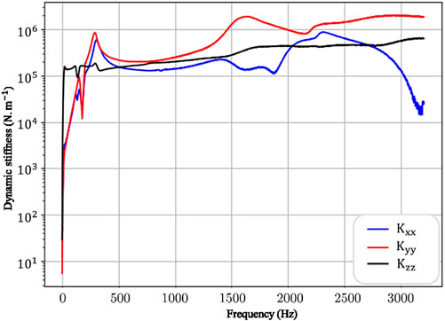
FIGURE 8. Results of the D-IS method for the M-I-M system.
Given the axial symmetry of the isolator, the stiffness along Tx and Ty are expected to be equal. However, the stiffnesses identified according to Tx and Ty appear to agree only at low frequencies. These discrepancies may, in part, be due to the compact and unstable nature of the assembly, which oscillates widely when excited. Regarding the Tz Dof, the stiffness is very stable and exhibits the expected tendency of a spring element. Although a reasonable prediction seems to have been made according to Tz, the identification would likely be improved by using a more stable assembly.
The resonance method was used to validate the results of the Direct In-Situ (D-IS) method. This method simply consists of identifying the resonant frequency of an insulator supporting a known mass m. Then, using the value of the mass, we can determine the value of the stiffness corresponding to the resonance frequency:
Figure 9 shows the experiments carried out, the aim of which is to determine the resonance frequencies according to the 3 DOF in translation, for 3 different masses, from a measurement of FRF.

FIGURE 9. FRF measurement on test benches M3-I-TB (A–C), M2-I-TB (D–F) and M1-I-TB (G,–I).
Figure 10 presents the results of the resonance method and the D-IS method carried out on the M2-I-M3 test bench. We can see that a good agreement is obtained between the two methods except for the point corresponding to the smallest mass (according to Tx and Ty). This error is probably due to the assumption that the mass of the isolator is negligible compared to that of the mass M1 (which is not the case for a small mass). This discrepancy may also, in part, be due to the low precision of the measurement of mobility at low frequencies. Using a softer impact tip may improve results in this case.
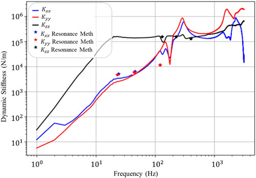
FIGURE 10. Comparison between the dynamic stiffness obtained by the D-IS method and the resonance method.
Although a good agreement is obtained between the two methods, this result is conclusive only for low frequencies. Hence the interest of validation by the TPA Mount Stiffness method.
The determination of the dynamic stiffness is limited to the round trip in situ method’s translational Tz Dof (along the isolator axis). The objective is to determine the stiffness along Tz using only FRFs measured along the same Dof. The system used in the experimental validation is the test bench P-I-P. The different measurement steps of the RT-IS method conducted on the system are presented in Figure 11.
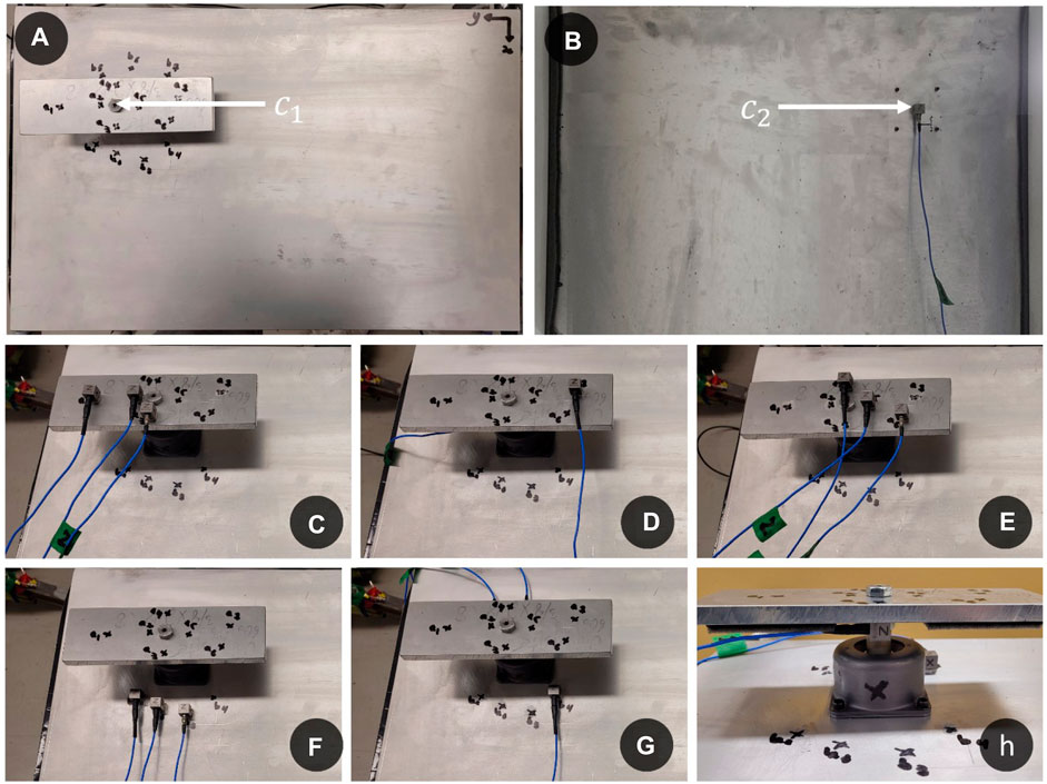
FIGURE 11. RT-IS on the P-I-P system, Connection points
Figure 12 shows the dynamic stiffness predictions using the round trip in situ method. Although the excitations are primarily along the Z-axis, predictions were also made along Tx (blue) and Ty (red).
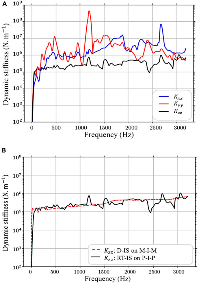
FIGURE 12. Dynamic stiffness identified (A) with the RT-IS method for the P-I-P system (B) comparison of the Z-axis stiffness with that obtained with the D-IS method for the M-I-M system.
As expected, for these Dofs, mobility generally seems to be underestimated. Concerning the value of the dynamic stiffness along the Z-axis, by comparing the results obtained on the two test benches [see Figure 12B], we can see that the general trend agrees with the one measured on the M-I-M test bench. Indeed, some regions clearly disagree, especially between 1,150 Hz and 1800 Hz.
A second area of detuning can be observed at high frequencies, from 2,400 Hz. The difference between the two results is undoubtedly associated with measurement errors (resonance of the system) of the round trip in situ method on the P-I-P system.
In this section, the stiffnesses determined on the B-I-P test rig will be further validated with the Mount Stiffness method of the classical transfer path analysis family. The measurements performed are presented in Figure 13 and summarized in the following table.
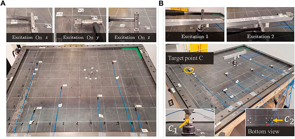
FIGURE 13. Experimental tests related to the application of the Mount Stiffness method on the B-I-P test bench (A) FRF measurements on the decoupled system (B) Operational measurements on the coupled system.

TABLE 1. Summary of measurements.
Six target points are considered to apply the Mount Stiffness method of transfer path analysis, and two types of operational excitation are applied. The objective is to predict the vibration response using the stiffness identified by the D-IS and RT-IS methods. The quality of the prediction will give an idea about the accuracy of the technique used to identify the dynamic stiffness.
The in situ identification of the dynamic stiffness and the application of several TPA methods require the inversion of a matrix of frequency response functions (FRFs). As part of this work, the truncation method is used, it simply consists in replacing by zero all the singular values corresponding to the measurement noise. The problem is that the gap between large and small singular values is not always easy to detect. There are several methods (Jan, 1997; Janssens et al., 1999; Thite and Thompson, 2003) to establish a threshold below which singular values are rejected. The regularization parameter is simply the number of singular values to retain. This parameter was carefully chosen to retain only the singular values corresponding to the dominant degrees of freedom (outside the plane). This reduces dimensionality while preserving essential transfer path information for analyzing over-dimensioned systems (Hansen, 1998; ROOZEN et al., 2012).
Figure 14 shows the results of the Mount Stiffness method applying excitation 1 according to Tz. The first column corresponds to the amplitude and phase, the second corresponds to the amplitude difference, and the third correspond to the same results in terms of box plots and histograms to facilitate the comparison of the presented stiffness identification methods.
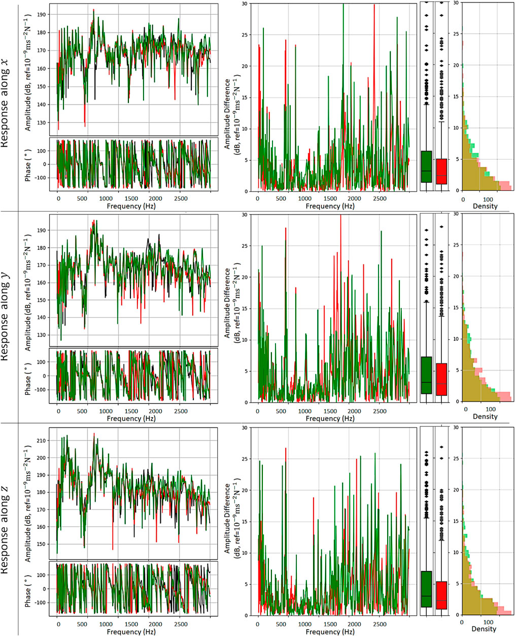
FIGURE 14. Results of the TPA Mount Stiffness method (excitation 1 according to Tz).
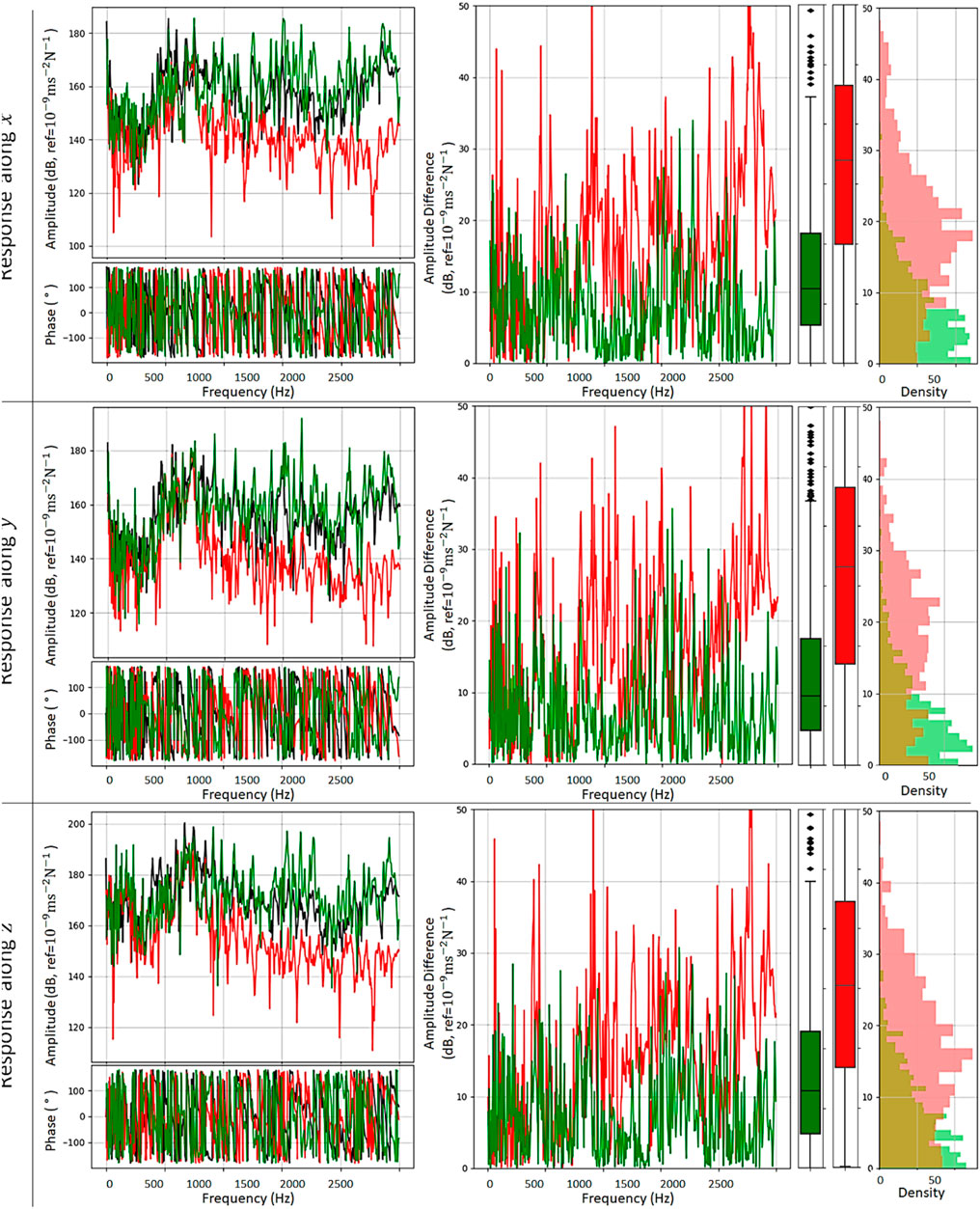
FIGURE 15. Results of the TPA Mount Stiffness method (excitation 2 according to Tx).
The black curve and the reconstructed responses represent the reference response at the target point:
⁃ Using the stiffness from the D-IS method is represented by the green curve,
⁃ Using the stiffness from the RT-IS method is represented by the red curve.
Since the result of the other points is similar, the presented response corresponds only to the first target point, according to Tx, Ty and Tz. Predictions are made using the stiffness obtained by the D-IS method according to Tx, Ty and Tz, and that obtained by the RT-IS method according to Tz. The reference response is directly measured. Comparing the predicted responses to the reference response, the responses are predicted with considerable accuracy, where many resonances have been predicted with reasonable precision. From the error curves, box plots and histograms, the amplitude difference corresponding to RT-IS is globally more minor than that corresponding to D-IS. Thus, the RT-IS method provides overall better prediction than D-IS over the studied frequency range. This highlights the potential use of this in situ characterization method, which allows for the overdetermination of the problem and reduced errors in the inversion.
The differences at low frequencies are probably due to the neglected out-of-plane Dofs, which are essential to describe the behavior of the receiver plate at low frequencies. It should be remembered that the results presented are calculated with only part of the dynamic stiffness (
At mid and high frequencies, the observed deviations are likely the result of an identified stiffness error. The variations may also be caused by the fact that only one transfer path, located in the middle of the isolator, was considered instead of 4 transfer paths. Moreover, the misalignment of the connection points on both sides of the isolator can also influence the identified stiffness.
To test the
However, the corresponding RT-IS curve shows an apparent disagreement with the reference. This is expected since the main transfer paths have been neglected in this calculation: only the stiffness along Tz is used to transfer an excitation along Tx.
In this paper, the main in situ dynamic stiffness identification methods and TPA methods have been presented. In situ identification methods for dynamic stiffness, due to their remarkable practicality compared to traditional methods, are certainly part of the future of interface characterization methods. Seeking to apply these methods on resonant systems representative of industrial applications, where access to interface points is generally difficult. Experimental validation of the direct in situ and round trip in situ methods were performed, comparing the results with those of the resonance and mount stiffness methods of the classical transfer path analysis. It demonstrated their use, and the results provided evidence that the decoupled isolator stiffness can be determined from mobility measured on the coupled system without or with the excitation of the interface points, and that the round trip in situ method facilitates the overdetermination of the problem, which allows stabilizing the inversion step. Overall, the experimental validation of dynamic stiffness identification methods showed good agreement at low frequencies. The comparison of the two methods, direct in situ and round trip in situ, showed that the round trip in situ method allows the use of remote measurement positions and the overdetermination of the problem, which reduces the error in the inversion. The obtained stiffnesses were further validated with the transfer path analysis mount stiffness method, and used to predict the response of another system, thus showing the independent nature of the identified dynamic stiffness.
The raw data supporting the conclusion of this article will be made available by the authors, without undue reservation.
RS: Conceptualization, Investigation, Writing–review and editing. WE: Methodology, Writing–original draft, Writing–review and editing. RC: Methodology, Supervision, Validation, Writing–review and editing. NA: Formal Analysis, Methodology, Supervision, Validation, Writing–review and editing.
The author(s) declare that no financial support was received for the research, authorship, and/or publication of this article.
We want to thank the Parker Hannifin Canada company for providing us with the isolator, which was the subject of our study. The authors would like to thank the ETS (École de Technologie Supérieure) team for his help during the experimental measurements carried out at GRAM (Groupe de recherche en acoustique à Montréal).
The authors declare that the research was conducted in the absence of any commercial or financial relationships that could be construed as a potential conflict of interest.
The author NA declared that they were an editorial board member of Frontiers at the time of submission. This had no impact on the peer review process and the final decision.
All claims expressed in this article are solely those of the authors and do not necessarily represent those of their affiliated organizations, or those of the publisher, the editors and the reviewers. Any product that may be evaluated in this article, or claim that may be made by its manufacturer, is not guaranteed or endorsed by the publisher.
Aerospace & Defense Isolator Catalog/ Vibration (2017). Shock & motion control products for sensitive equipment, shipping containers & aircraft interiors. LORD Corporation OD PC6116 (Rev.3 8/17).
Basner, M., Babisch, W., Davis, A., Brink, M., Clark, C., Janssen, S., et al. (2014). Auditory and non-auditory effects of noise on health. Lancet 383 (9925), 1325–1332. doi:10.1016/s0140-6736(13)61613-x
De Sitter, G., Devriendt, C., Guillaume, P., and et Pruyt, E. (2010). Operational transfer path analysis. Mech. Syst. Signal Process. 24 (2), 416–431. doi:10.1016/j.ymssp.2009.07.011
Diez-Ibarbia, A., Battarra, M., Palenzuela, J., De-la-Cruz, M., et al. (2017). Comparison between transfer path analysis methods on an electric vehicle. Appl. Acoust. 118, 83–101. doi:10.1016/j.apacoust.2016.11.015
Dubbaka, K. R., Zweng, F. J., and Shan, U. (2003). Application of noise path target setting using the technique of transfer path analysis. SAE Technical Paper.
Elliott, A. S., Moorhouse, A. T., Huntley, T., and et Tate, S. (2013). In-situ source path contribution analysis of structure borne road noise. J. Sound Vib. 332 (24), 6276–6295. doi:10.1016/j.jsv.2013.05.031
Hansen, P. C. (1998). Rank-deficient and discrete ill-posed problems: numerical aspects of linear inversion. Philadelphia, USA: Society for Industrial and Applied Mathematics, 263.
Hogan, N. (1988). On the stability of manipulators performing contact tasks. IEEE J. Robotics Automation 4 (6), 677–686. doi:10.1109/56.9305
Ingle, S. T., Pachpande, B. G., Wagh, N. D., and Attarde, S. B. (2005). Noise exposure and hearing loss among the traffic policemen working at busy streets of Jalgaon urban centre. Transp. Res. Part D 10, 69–75. doi:10.1016/j.trd.2004.09.004
Jan, W. (1997). Verheij, inverse and reciprocity methods for machinery noise source characterization and sound path quantification Part 1: sources. Int. J. Acoust. Vib. 2 (1), 11–20.
Janssens, K., Gajdatsy, P., Gielen, L., Mas, P., Britte, L., Desmet, W., et al. (2011). OPAX: a new transfer path analysis method based on parametric load models. Mech. Syst. Signal Process. 25 (4), 1321–1338. doi:10.1016/j.ymssp.2010.10.014
Janssens, M. H. A., Verheij, J. W., and Thompson, D. J. (1999). The use of an equivalent forces method for quantifying structural sound transmission in ships. J. Sound. Vibr 226, 305–328. doi:10.1006/jsvi.1999.2303
Meggitt, J. "On in-situ methodologies for the characterisation and simulation of vibro-acoustic assemblies." doi:10.13140/RG.2.2.32585.804832017).
Meggitt, J. W. R., Elliott, A. S., Moorhouse, A. T., and Lai, K. H. (2015). In-situ determination of dynamic stiffness for resilient elements.
Meyer, V., Leissing, T., and Audoly, C. (2016). A condensed transfer function method as a tool for solving vibroacoustic problems. Proc. Institution Mech. Eng. Part C J. Mech. Eng. Sci. 230 (6), 928–938. doi:10.1177/0954406215615627
Moorhouse, A. T., and Elliott, A. S. (2013). The 'round trip' theory for reconstruction of Green's functions at passive locations. J. Acoust. Soc. Am. 134 (5), 3605–3612. doi:10.1121/1.4821210
Moorhouse, A. T., Evans, T. A., and Elliott, A. S. (2011). Some relationships for coupled structures and their application to measurement of structural dynamic properties in situ. Mech. Syst. Signal Process. 25 (5), 1574–1584. doi:10.1016/j.ymssp.2010.12.016
Patil, N., Elliott, A., and et Moorhouse, A. (2015). “Transfer path analysis method applied to diagnostic testing of sound insulation performance of cavity constructions,” in Noise and vibration - emerging technologies (Croatie: Dubrovnik), 1–7.
Patil, N. (2019). “Application of impact hammers without inbuilt force transducer towards isolator dynamic stiffness and blocked force measurements,” in INTER-NOISE and NOISE-CON congress and conference proceedings (Institute of Noise Control Engineering), 6204–6213.
Plunt (2005). Finding and fixing vehicle NVH problems with transfer path analysis. Sound. Vib. 39 (11), 12–16.
Roozen, N. B., Leclere, Q., and Sandier, C. (2012). “Operational transfer path analysis applied to a small gearbox test set-up,” in Acoustics 2012. Editor S. F. d’Acoustique (Nantes, France).
Somers, H. (2005). "Round-trip translation: what is it good for?" In: Proceedings of the australasian language technology workshop, 127–133.
Stansfeld, S. A., and Matheson, M. P. (2003). Noise pollution: non-auditory effects on health. Br. Med. Bull. 68 (1), 243–257. doi:10.1093/bmb/ldg033
Thite, A. N., and Thompson, D. J. (2003). The quantification of structure-borne transmission paths by inverse methods. Part 1: improved singular value rejection methods. J. Sound Vib. 264, 411–431. doi:10.1016/s0022-460x(02)01202-6
van der Auweraer, H., Mas, P., and Dom, S. (2007). Transfer path analysis in the critical path of vehicle refinement: the role of fast, hybrid and operational path analysis.
van der Seijs, M. V., de Klerk, D., and Rixen, D. J. (2016). General framework for transfer path analysis: history, theory, and classification of techniques. Mech. Syst. Signal Process. 68-69, 217–244. doi:10.1016/j.ymssp.2015.08.004
Wienen, K., Sturm, M., Moorhouse, A. T., and Meggitt, J. (2021). Generalised round-trip identity—for the determination of structural dynamic properties at locations inaccessible or too distant for direct measurement. J. Sound Vib. 511, 116325. doi:10.1016/j.jsv.2021.116325
Keywords: interface isolation, dynamic transfer stiffness, in situ measurements, direct insitu method, round trip, transfer paths analysis, vibrational isolator
Citation: Slimane R, El Khatiri W, Cherif R and Atalla N (2023) Dynamic stiffness identification methods: experimental study and validation. Front. Acoust. 1:1277431. doi: 10.3389/facou.2023.1277431
Received: 14 August 2023; Accepted: 06 October 2023;
Published: 07 November 2023.
Edited by:
Minghui Lu, Nanjing University, ChinaReviewed by:
Hui Guo, Shanghai University of Engineering Sciences, ChinaCopyright © 2023 Slimane, El Khatiri, Cherif and Atalla. This is an open-access article distributed under the terms of the Creative Commons Attribution License (CC BY). The use, distribution or reproduction in other forums is permitted, provided the original author(s) and the copyright owner(s) are credited and that the original publication in this journal is cited, in accordance with accepted academic practice. No use, distribution or reproduction is permitted which does not comply with these terms.
*Correspondence: Wafaa El Khatiri, welkhatiri@gmail.com
†Present address: Wafaa El Khatiri, Research, Development and Innovation Laboratory, Mundiapolis University, Casablanca, Morocco
Disclaimer: All claims expressed in this article are solely those of the authors and do not necessarily represent those of their affiliated organizations, or those of the publisher, the editors and the reviewers. Any product that may be evaluated in this article or claim that may be made by its manufacturer is not guaranteed or endorsed by the publisher.
Research integrity at Frontiers
Learn more about the work of our research integrity team to safeguard the quality of each article we publish.