 Xinqiao Chen
 Siyuan Dai1
- 1School of Information and Communication Engineering, Communication University of China, Beijing, China
- 2School of Electronic Engineering, Beijing University of Posts and Telecommunications, Beijing, China
This study proposed a novel scheme for filterless frequency 32-tupling millimeter wave (MMW) generation based on two cascaded dual-parallel Mach–Zehnder modulators (DPMZMs). When the MZMs are biased on a maximum transmission point and the phase difference of the radio frequency (RF) driving voltage between the two MZMs in DPMZM is
1 Introduction
Millimeter wave (MMW) signals [1] have been considered a solution in many applications such as broad wireless communication [2, 3], radar [4, 5], phased-array antennas [6, 7], modern instruments, imaging [8, 9], biomedical uses, and terahertz applications [10–12]. Due to the limited response bandwidth of electronic devices and equipment, it is difficult to generate and process MMW signals beyond 100 G through conventional electronics [13]. MMW generation in the optical domain can overcome the limitations of response frequency and electric device bandwidth and offers multiple advantages, such as high frequency, high spectrum purity, and wide frequency tunability [14, 15]. Therefore, MMW generation in the optical domain has become a hot research topic and has been extensively studied in recent years.
The fundamental principle to generate MMW signals in the optical domain is to heterodyne two optical waves of different wavelengths which beat at a photodetector (PD), in which the generated MMW frequency is the frequency space of the two optical waves. The methods proposed to generate MMW in the optical domain can be roughly divided into five kinds: 1) direct modulation [16]; 2) optical heterodyne [17, 18]; 3) frequency up-conversion [19]; 4) external modulation [20]; 5) nonlinear [21–23] [such as four-wave mixing (FWM), stimulated Brillouin scattering (SBS), cross-phase modulation (XPM), cross-gain modulation (XGM)]; 6) optoelectronic oscillator (OEO) [24, 25]. Among those methods, the external modulation method has evident advantages, such as high modulation bandwidth, high tunability, high-frequency responsiveness, high spectral purity of the generation signal, and excellent system stability. Thus, the current research focuses on MMW generation based on external modulation technology [26].
The main commercial external modulators include the Mach–Zehnder modulator (MZM), phase modulator (PM), and polarization modulator (PoIM). MMW generation with PoIM requires careful control of the polarization of devices and increases the cost of the system. The purity to generate MMW with PM is low. MMW generation with MZMs offers higher reliability, higher frequency multiplication factor [FMF], low phase noise, and frequency tunability; thus, it has become the main method to generate MMWs in the optical domain [27].
The external modulation method is based on beating the desired ± nth-order sidebands generated by an optical modulator at a photodetector (PD). The frequency of the generated MMWs is
Until now, using a single MZM, the highest FMF that had been obtained is 8 [28]. To increase the FMF, the general method is to cascade multiple MZMs. The most common method is to cascade two MZMs, which are linked in series or parallel, and can produce ±4n-order sidebands and obtain FMFs of 8 and 16. The structure formed by two parallel modulators is often called a dual-parallel MZM (DPMZM). To further improve FMF, a structure combining four modulators is typically used. In this structure, the four modulators are separated into two groups, and each group contains two modulators that can be connected in series or in parallel. The two group modulators can also be linked in parallel or in series. The main types combined by four modulators are as follows: 1) four in parallel, which can be regarded as two DPMZMs connected in parallel [29]; 2) four in series [30]; 3) two groups connected in parallel, with each group comprising two MZMs in series [31]; and 4) two DPMZMs connected in series [32]. With the structure combining four modulators, the FMF can reach 16, 24, and 32. The proposed frequency 32-tupling scheme needs the remodulation technique [32], which results in low purity and complex structure. Recently, schemes to generate 32-tupling frequency millimeter waves using eight [33] and four [34] polarization modulators with mixed connections have been proposed; however, the limitation of these schemes is that the polarization devices have a complex and higher sensitivity to the state of polarization. To generate high-purity MMW signals, it is necessary to suppress unwanted sidebands and optical carriers. There are two main ways to suppress undesired sidebands. One way is to use different modulators with different RF driving signals so that the resulting undesired sidebands are in opposite phases [35] and can be canceled out by combining them. The other way is to use a wavelength-selective device to filter out undesired or desired sidebands [36]. For carrier suppression, one method is to filter out the carrier with a filter, which will reduce the output signal power. Another method is to use the structure of the variable optical attenuator and π phase shifter to cancel the optical carrier component [37], which will also reduce the output signal power. However, another way is adopting a polarization structure to cancel out the carrier wave.
The main parameters to measure the purity of the generated MMW are optical sideband suppression ratio (OSSR) and RF spurious suppression ratio (RFSSR). In general, the larger the OSSR, the larger the RFSSR. In the engineering applications of wireless communication, the RFSSR is generally required to be >15 dB [38]. To compare the main characteristics of MMW generation based on the structures of the proposed four MZMs, the list is as Table 1 shows.
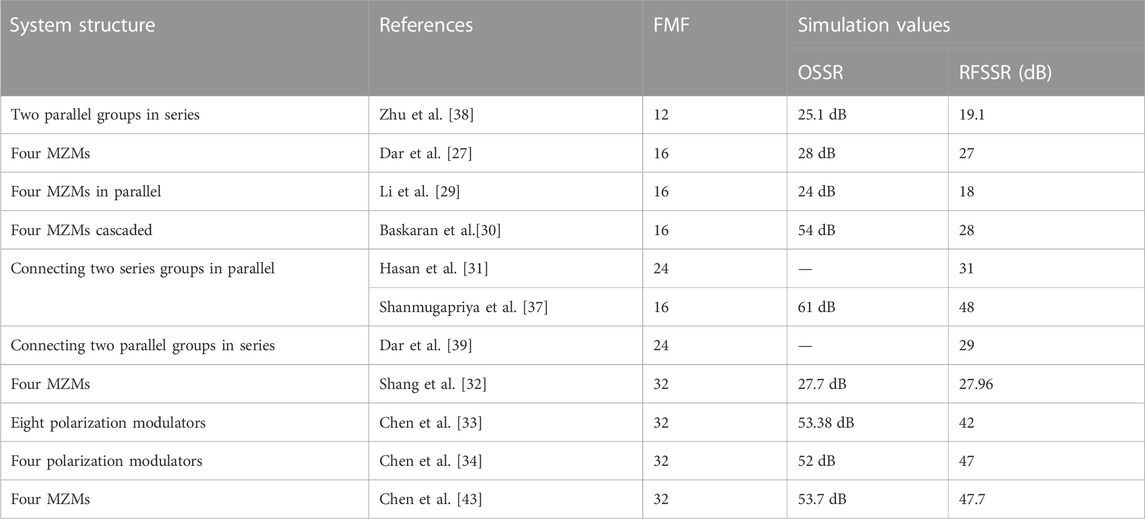
TABLE 1. Main characteristics of MMW generation based on the structure of two DPMZMs.
This work proposes a new scheme based on two cascaded DPMZMs to generate frequency 32-tupling MMWs. First, the principle of generating frequency 32-tupling MMW is analyzed theoretically. Then, a simulation experiment is designed to verify the feasibility of the scheme, and the influence of the main parameters of the system device on the OSSR and RFSSR generated by frequency 32-tupling MMW is studied experimentally. Finally, a short summary of the thesis is given.
2 Configuration/setup and principle
Figure 1 shows the diagram of the system designed to generate frequency 32-tupling MMW based on two cascaded DPMZMs. The system consists of an RF signal generator, continuous wave (CW) laser, polarization beam splitter (PBS), polarization controller (PC), electrical phase shifter (EPS), power splitter, MZM, power combiner, polarization beam combiner (PBC), polarizer (Pol), optical amplifier (OA), and photodetector (PD).
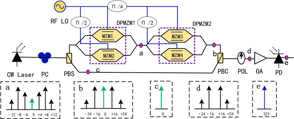
FIGURE 1. Schematic of frequency 32-tupling MMW generation based on two DPMZMs cascaded. CW, laser, continuous-wave laser; PC, polarization controller; RF LO, radio frequency local oscillator; PBS, polarization beam splitter; PBC, polarization beam combiner; Pol, polarizer; MZM, Mach–Zehnder modulator; DPMZM, dual-parallel MZM; OA, optical amplifier; PD, photodetector.
The optical carrier from the CW laser passes through the PC and the PBS successively, then is split into two beams along the x- and y-axes, and fed into the upper and lower branches of the system, respectively. The input optical signal of the upper branch is split into two beams first via the optical power splitter and then poured into MZM1 and MZM2, respectively. The output optical signals from MZM1 and MZM2 are combined into one beam by the optical power combiner and then divided into two beams by the optical power splitter and then poured into MZM3 and MZM4, respectively. The output optical signals from MZM3 and MZM4 are combined by a power combiner. The output optical signals from the upper and lower branches are combined by PBC and after the combined signal passes through the Pol and OA successively, which is finally poured into the PD to finish the photoelectric conversion.
The initial phases of the RF signals loaded into MZM1, MZM2, MZM3, and MZM4 are set to 0°, 90°, 45°, and 135°, respectively, by three EPS. By adjusting the modulation index of the MZMs, the main components of the output signals from the second DPMZM are ±16th-order optical sidebands and optical carrier. The PC before the PBS is used to control the optical power distribution ratio in the x- and y-axis directions. The angles of the PC and Pol are adjusted to the special values to let the optical carrier component of the output signals from the upper and lower branches cancel each other out. Then, the remainder components from Pol are ±16th-order sidebands, which are beat in the PD and the frequency 32-tupling MMW is generated.
2.1 The output of DPMZM
The output of MZM can be expressed as follows:
In Eq. 1,
Supposing that
Substituting
When the MZM is biased at the maximum transmission point (MATP),
In Eq. 3,
When the initial phase difference of the two RF driving voltages loading at the two MZMs in the DPMZM is set to
The purpose of setting the initial phase difference of the two MZMs at
2.2 The output of two cascaded DPMZMs
For the two cascaded DPMZMs, the second DPMZM input signal is the output of the first DPMZM. When the
Since the Bessel function decreases with order and argument, values greater than
The purpose of setting the phase difference of the RF driving signal loading two DPMZMs to
Assume that the incident light carrier wave from the CW laser is
In Eq. 7,
Substituting
where
From Eq. 8, the amplitudes of the signal from the second DPMZM are proportional to the
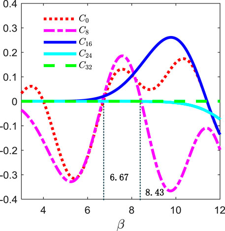
FIGURE 2. Relationship between
2.3 The suppression of 0-order and ±8-order optical sidebands
To obtain high-purity frequency 32-tupling MMW, the optical sidebands except for the ±16th-order must be suppressed as much as possible. According to the characteristic of the Bessel function, the
To suppress the ±8th-order sidebands, we adopt a method to make the
To suppress the optical carrier, we adopt the method of polarization multiplexing. By setting the polarization angle of Pol to 45°, the output light field of the Pol is expressed as
From Eq. 9, the optical carrier can be completely suppressed when
After suppressing the ±8th-order sidebands and carrier, the output of the Pol in this case is
From Eq. 11, the ±24th-order optical sidebands are the maximum spurious sidebands. The OSSR can then be determined
After the optical signal output from Pol is beaten in the PD, the frequency 8n-tupling MMW signals are generated. According to Eq. 11, the output of PD can be expressed as
In Eq. 13,
3 Simulation
A simulation link based on the structure in Figure 1 is set up using OptiSystem photonic software. The main parameters of the devices in the simulation experiment system are shown in Table 2. The values of the parameter of the devices in Table 2 are chosen as follows: The value of the “azimuth of the polarization controller” is chosen according to Eq. 10. The value of the “amplitude of the RF locator” is chosen based on β = 8.43, where
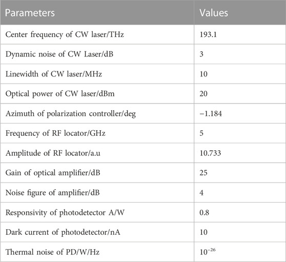
TABLE 2. Main parameters of the devices involved in the simulations.
Figures 3A, B show the spectrum at points a and b in Figure 1, respectively. Figure 3A shows that the outputs of the first DPMZM are ±4nth-order optical sidebands, where the amplitudes of the optical sidebands with n > 3 are very small. Figure 3B shows that the outputs of the second DPMZM are ±8nth-order optical sidebands, where the amplitudes of the sidebands with n > 3 are very small. Figure 4 shows the spectrum of the signal from the Pol, in which the carrier component is well-suppressed and the main components of the signals are ±16th-order optical sidebands located at 193.02 THz and 193.18 THz, respectively. They have an interval of 160 GHz, which is 32 times the frequency of the RF drive signal. The ±24th-order sidebands are the largest spurious sidebands and lower 53.53 dB than the ±16th-order sidebands, indicating that the OSSR is 53.53 dB, which is very close to the theoretical value of 53.7 dB calculated by Eq. 12. The power of the ±16th-order optical sidebands is 69.31 dB higher than that of the center carrier, which indicates that the optical carrier is well-suppressed.
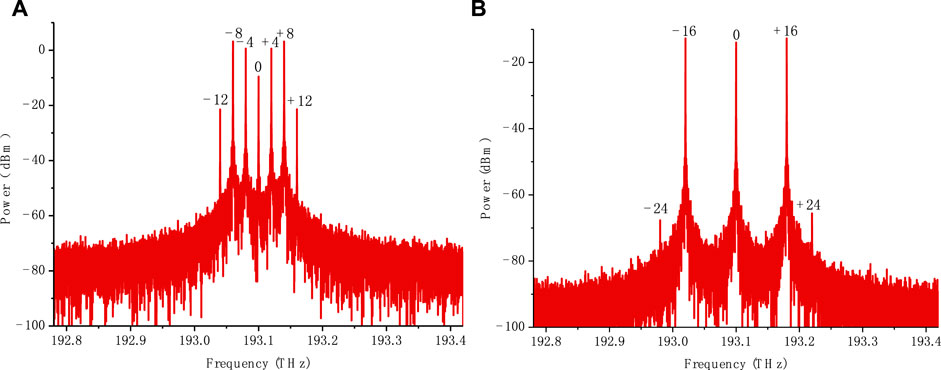
FIGURE 3. Spectrum of the output optical signal from two DPMZMs. (A) The first DPMZM. (B) The second DPMZM.
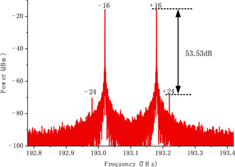
FIGURE 4. Optical spectrum from Pol.
Figure 5 shows the spectrum of the signal output from the PD, in which the 160 GHz MMW signal is highest, which is 32 times the frequency of the 5 GHz RF drive signal. Moreover, the 200 GHz MMW is the largest RF spurious signal, which is 40 times the frequency of the RF drive signal, with a power value lower at 47.33 dB than that at 160 GHz, indicating that the RFSSR value is 47.33 dB, which is very close to the theoretical value of 47.7 dB calculated by Eq. 14.
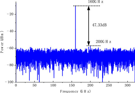
FIGURE 5. Spectrum from PD.
4 Analysis of the effects on the OSSR and RFSSR
The OSSR and RFSSR are significant parameters used to evaluate the quality of the generated signals. The previous theoretical analysis demonstrated that setting the device parameters is the key to obtaining high-purity frequency 32-tupling MMW. When the parameters deviate from the theoretical value, it decreases the purity of the generated MMW. The main parameters of the devices that affect the purity of MMW mostly are the extinction ratio (ER) and DC drift of the MZM, the amplitude and initial phase of the RF drive signal, and the azimuth of the PC. When these parameters deviate from the design values obtained from the theoretical analysis, they inevitably reduce the purity of the produced signal.
4.1 Effect of the MZM extinction ratio
In general, the ER value plays an important role in system design, and there are certain restrictions on the ER value [40-41]. The relationship curves of OSSR and RFSSR with MZM extinction ratios are shown in Figure 6. When the extinction ratio of MZM is swept from 10 dB to 60 dB, the more MZMs, the greater the influence on OSSR and RFSSR. When the extinction ratio of MZM reaches approximately 35 dB, the value of RFSSR tends to be stable at 47.3 dB. When the extinction ratio is >18 dB, the RFSSR value is >15 dB, which can meet the transmission needs of general links.
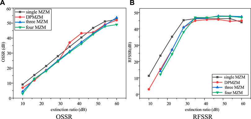
FIGURE 6. Relationship of OSSR and RFSSR with the extinction ratio. (A) OSSR. (B) RFSSR.
According to the literature [42], the relationship between the power splitter ratio
4.2 Effect of the initial RF drive signal
The initial phases of the RF drive signal loaded into the DPMZMs are set by the 45° EPS and 90° EPS, and the relationship between the offset of initial phases deviates from the design values and the OSSR and RFSSR are obtained by simulation.
The relationship between the deviations of the initial phase of the EPS and the OSSR is shown in Figure 7A. The OSSR drops from 51.79 dB to 12.86 dB when the deviation reaches ±1.5° from
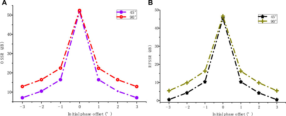
FIGURE 7. Relationship between the initial phase deviation and the OSSR and RFSSR. (A) OSSR. (B) RFSSR.
The relationship between the initial phase deviation of the EPS and the RFSSR is shown in Figure 7B. Deviations of 45° and 90° EPS are within ±0.5° from
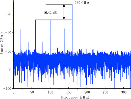
FIGURE 8. Output signal spectrum with the initial phase at 45.5°.
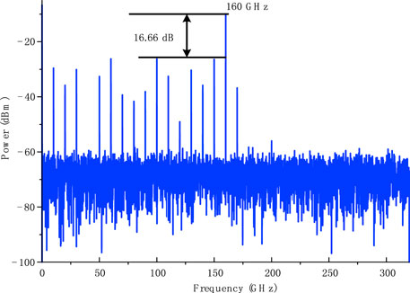
FIGURE 9. Output signal spectrum with the initial phase at 91°.
4.3 Effect of the amplitude of the RF drive signal
The amplitude of the RF drive signal determines the value of the modulation index β of the MZMs. Figure 10 shows the relationship between OSSR and RFSSR with
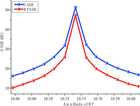
FIGURE 10. Relationship between the amplitude of the RF and the OSSR and RFSSR.
4.4 Effect of PC azimuth
The azimuth of the PC determines whether the carrier component of the output optical signal from Pol can be effectively suppressed. From the previous theoretical analysis, the theoretical value of the azimuth of the PC is −1.184°. The relationships between the values of OSSR and RFSSR and the azimuth of PC deviation are shown in Figure 11. As shown in Figure 12, when the azimuth deviation of the PC is within 11.6% of the theoretical value, the RFSSR is not less than 15.42 dB, which can meet the requirements of a general transmission link.
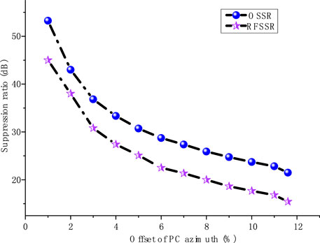
FIGURE 11. Curves of OSSR and RFSSR with PC azimuthal deviation values.
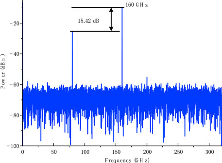
FIGURE 12. RF spectrum at 11.6% PC azimuthal deviation.
4.5 Effect of DC bias drift of the MZM
In MZM-based methods of MMW generation, DC bias drift is the key factor influencing signal quality. The relation curves between the DC drift and OSSR and RFSSR are obtained by simulation. As shown in Figure 13, the value of RFSSR decreases to 15.71 dB when the DC drift is within 0.12 V, which can satisfy the requirements of general communication systems.
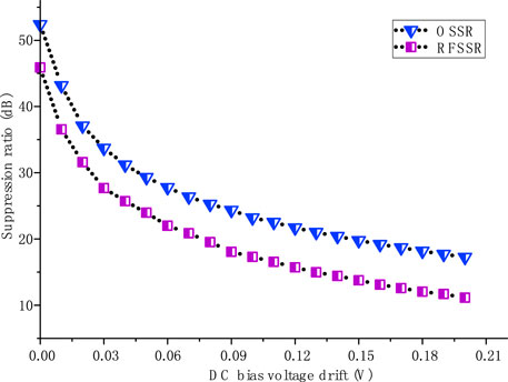
FIGURE 13. elationship between the bias voltage drift and the OSSR and RFSSR.
5 Discussion
Suppressing the carrier in the generation of optical millimeter waves is a key issue. In [43], an adjustable 1 × 2 optical splitter and 180° phase shifter are adopted to suppress the carrier wave in the system. The splitting ratio of the splitter is set to 0.88:0.12 based on the theoretical analysis. Due to the limitations of the fabrication process, it is costly to manufacture a tunable 1 × 2 optical beam splitter with 1% accuracy. In addition, the splitting ratio of the splitter varies with the input wavelength and temperature. In this work, we propose a method to suppress the optical carrier based on polarization multiplexing, which does not need costly tunable devices. The carriers are suppressed by adjusting the polarization direction of the polarization devices, which is easier to implement in engineering.
The FMF of generated millimeter wave with our scheme is 32. The main problem for our scheme is the high modulation index of MZM, which will increase the complexity of the system and the difficulty of realization. To solve this problem, remodulation schemes have been proposed in recent years. The FMF of the generated millimeter wave can also reach 32 using remodulation schemes in the literature [32]. Their advantages and disadvantages need to be compared. Our scheme adopts two dual-parallel MZMs in the system structure and polarization multiplexing is used for optical carrier suppression. In the literature [32], the structure of two dual-parallel MZMs has also been adopted. Compared with the system structure, the complexity of the system is basically the same; however, the remodulation structure will introduce an optical phase difference, resulting in a decline in the quality of the generated signal. The modulation index in our scheme is 8.43. The modulation indexes in the literature [32] are 2.2 and 3.94 for primary modulation and secondary modulation, respectively. The OSSR and RFSSR obtained in our scheme are 53.53 dB and 47.33 dB, respectively, compared to 27.7 dB and 27.96 dB in the literature [32]. The modulation index in the literature [32] is lower than our scheme, which will reduce the difficulty of implementation, but their OSSR and RFSSR are lower than those in our scheme.
In engineering applications for our designed ROF system, if it is used only to generate 32-tupling MMW, it does not need any optical filters. However, downlink data must be transmitted, a total reflection filter is needed to filter the +16th order sideband with the downlink data modulated in the center station. This could be realized by using an FBG with 100% reflectivity. If we need to transmit uplink data for carrier reuse in the base station, a tunable rejection filter is needed to reflect part of the −16th-order sideband and the uplink data modulated on it. This could be achieved by using a tunable rejection FGB. To obtain better system performance, the requirements for the total reflection FBG are low insert loss and high reflection ratio, while the requirements for the tunable FBG are low loss and reflectance and transmittance accuracy above 1%.
The development trends of the generation of millimeter waves based on MZMs are increased millimeter wave frequency; simplified system structure; improved purity of the generated millimeter wave signal.
6 Conclusion
This work proposed a novel scheme to generate 32-tupling frequency MMW based on two cascaded DPMZMs. A theoretical analysis of the generation frequency of the 32-tupling MMW was performed. The calculated OSSR and RFSSR values of the generated signal were 53.7 dB and 47.7 dB, respectively. Based on the design of this paper, simulation experiments were carried out, with experimental OSSR and RFSSR values of the generated signals of 53.53 dB and 47.33 dB, respectively, which were close to the theoretical calculated values, thus verifying the feasibility of our scheme. The effects on the OSSR and RFSSR caused by deviation of the parameters, such as the extinction ratio of the MZMs, the initial phase and amplitude of the RF drive signal, the azimuth of PC, and the DC bias drift, were analyzed. To the best of our knowledge, this is the first time that an FMF as high as 32 has been achieved by two cascaded DPMZMs without the use of an optical filter. The RFSSR of the generated MMW was higher than that for proposed schemes with four cascaded MZMs. This method is expected to have critical promising applications in high-frequency millimeter and submillimeter waves as well as terahertz waves.
Data availability statement
The original contributions presented in the study are included in the article/Supplementary material; further inquiries can be directed to the corresponding author.
Author contributions
XiC and SD participated in the study design; XiC performed the study and collected important background information; ZL drafted the manuscript; XL and XuC provided assistance with the data analysis and plotted the graphs and tables; HX edited and generated the layout of the manuscript. All authors contributed to the article and approved the submitted version.
Funding
National Key Research and Development Project (2018YFB1404101).
Conflict of interest
The authors declare that the research was conducted in the absence of any commercial or financial relationships that could be construed as a potential conflict of interest.
Publisher’s note
All claims expressed in this article are solely those of the authors and do not necessarily represent those of their affiliated organizations, or those of the publisher, the editors, and the reviewers. Any product that may be evaluated in this article, or claim that may be made by its manufacturer, is not guaranteed or endorsed by the publisher.
References
1. Khan F, Pi Z. mmWave mobile broadband (MMB): Unleashing the 3–300GHz spectrum. In: 34th IEEE Sarnoff Symposium; 03-04 May 2011; Princeton, NJ, USA. IEEE (2011). p. 1–6.
2. Chen S, Zhao J. The requirements, challenges, and technologies for 5G of terrestrial mobile telecommunication. IEEE Commun Mag (2014) 52(5):36–43. doi:10.1109/mcom.2014.6815891
3. Li X, Yu J, Xiao J. Demonstration of ultra-capacity wireless signal delivery at W-band. J Lightwave Technol (2016) 34(1):180–7. doi:10.1109/jlt.2015.2462317
4. Wang YQ, Pei L, Li J, Li YQ. Millimeter-wave signal generation with tunable frequency multiplication factor by employing UFBG-based acousto-optic tunable filter. IEEE Photon J. (2017) 9(1):1–10. doi:10.1109/jphot.2017.2651982
5. Liu YL, Liang J, Li X, Xiao N, Zhang ZH, Yuan X. Theoretical investigation of photonic generation of frequency quadrupling linearly chirped waveform with large tunable range. Opt Express (2017) 25(14):16196–203. doi:10.1364/oe.25.016196
6. Cliché JF, Shillue B, Tetu M, Poulin M. A 100-GHz-tunable photonic millimeter wave synthesizer for the Atacama Large Millimeter Array radiotelescope. In: 2007 IEEE/MTT-S International Microwave Symposium; 03-08 June 2007; Honolulu, HI, USA. IEEE (2007). p. 349–52.
7. Lee BH, Roh W, Seol J, Park J, Lee J, Kim Y, et al. Millimeter-wave beamforming as an enabling technology for 5G cellular communications: Theoretical feasibility and prototype results. IEEE Commun Mag (2014) 52(2):106–13. doi:10.1109/mcom.2014.6736750
8. Sasaki A, Nagatsunia T. Reflection-type millimeter-wave imaging with a waveguide-mounted electro-optic sensor. In: Technical Digest. CLEO/Pacific Rim 2001. 4th Pacific Rim Conference on Lasers and Electro-Optics (Cat, No, 01TH8557); 15-19 July 2001; Chiba, Japan. IEEE (2001).
9. Sasaki A, Nagatsuma T. Reflection-type CW-millimeter-wave imaging with a high-sensitivity waveguide-mounted electro-optic sensor. Jpn J Appl Phys (2002) 41(1A):L83–6. doi:10.1143/jjap.41.l83
10. Kabir MA, Ahmed K, Hassan MM, Hossain MM, Paul BK. Design a photonic crystal fiber of guiding terahertz orbital angular momentum beams in optical communication. Opt Commun (2020) 475:126192. doi:10.1016/j.optcom.2020.126192
11. Li K, Chen Y, Huang Y, Li Y, Han J, Fu J, et al. 0.36 THz photonic terahertz-wave generation by simple optical frequency comb. Opt Fiber Tech (2021) 64:102581. 0. doi:10.1016/j.yofte.2021.102581
12. Wang SW, Lu Z, Zhang H, Yang Z, Zhang L, Idrees N, et al. Photonic heterodyne generation of phase-coded terahertz signals. Opt Commun (2021) 499:127253. doi:10.1016/j.optcom.2021.127253
13. Pi Z, Khan F. An introduction to millimeter-wave mobile broadband systems. IEEE Commun Mag (2011) 49(6):101–7. doi:10.1109/mcom.2011.5783993
14. Yao J. Microwave photonics. J Lightwave Technol (2009) 27(3):314–35. doi:10.1109/jlt.2008.2009551
15. Li W, Wang LX, Zheng JY, Li M, Zhu NH. Photonic MMW-UWB signal generation via DPMZM-based frequency up-conversion. IEEE Photon Technol Lett (2013) 25(19):1875–8. doi:10.1109/lpt.2013.2278867
16. Chen L, Pi Y, Wen H, Wen SC. All-optical mm-wave generation by using direct-modulation DFB laser and external modulator. Microw Opt Technol Lett (2007) 49(6):1265–7. doi:10.1002/mop.22449
17. Browning C, Delmade A, Lin Y, Geuzebroek DH, Barry LP. Optical heterodyne millimeter-wave analog radio-over-fiber with photonic integrated tunable lasers. In: Optical Fiber Communications Conference and Exhibition (OFC). IEEE; 03-07 March 2019; San Diego, CA, USA. Optical Society of America (2019). p. 1–3.
18. Li X, Xiao J, Xu Y, Yu JJ. QPSK vector signal generation based on photonic heterodyne beating and optical carrier suppression. IEEE Photon J. (2015) 7(5):1–6. doi:10.1109/jphot.2015.2486685
19. Wang C, Zhang Q, Wang W. Low-frequency wideband vibration energy harvesting by using frequency up-conversion and quin-stable nonlinearity. J Sound Vibration (2017) 399:169–81. doi:10.1016/j.jsv.2017.02.048
20. Zhang C, Ning TG, Li J, Pei L, Li C, Ma SS. A full-duplex WDM-RoF system based on tunable optical frequency comb generator. Opt Commun (2015) 344:65–70. doi:10.1016/j.optcom.2015.01.038
21. Wang T, Chen M, Chen H, Xie S. Millimetre-wave signal generation using FWM effect in SOA. Electron Lett (2007) 43(1):36–8. doi:10.1049/el:20072637
22. Chen HY, Chi YC, Lin CY, Tsai CT, Lin GR. Four-wave-mixing suppression of master-to-slave injection-locked two-wavelength FPLD pair for MMW-PON. J Lightwave Technol (2016) 34(20):4810–8. doi:10.1109/jlt.2016.2549061
23. Junker M, Schneider T, Lauterbach KU, Henker R, Schwarzbacher AT. High quality millimeter wave generation via stimulated Brillouin scattering. In: 2007 Conference on Lasers and Electro-Optics (CLEO); 06-11 May 2007; Baltimore, MD, USA. IEEE (2007). p. 1–2.
24. Li W, Kong F, Yao J. Arbitrary microwave waveform generation based on a tunable optoelectronic oscillator. J lightwave Technol (2013) 31:3780–6. doi:10.1109/jlt.2013.2287122
25. Brunetti G, Armenise MN, Ciminelli C. Chip-scaled ka-band photonic linearly chirped microwave waveform generator. Front Phys (2022) 10:785650. doi:10.3389/fphy.2022.785650
26. Chaudhuri RB, Barman AD, Bogoni A. Photonic 60 GHz sub-bands generation with 24-tupled frequency multiplication using cascaded dual parallel polarization modulators. Opt Fiber Technol (2020) 58:102244. doi:10.1016/j.yofte.2020.102244
27. Dar AB, Ahmad F, Jha RK. Filterless optical millimeter-wave generation using cascaded-parallel Mach–Zehnder modulators with tunable frequency multiplication factor. Opt Quant Electron (2021) 53(1):56–15. doi:10.1007/s11082-020-02666-1
28. Anand Prem PK, Chakrapani A. A millimeter-wave generation scheme based on frequency octupling using LiNbO3 mach-zehnder modulator. Natl Acad Sci Lett (2019) 42(5):401–6. doi:10.1007/s40009-018-0766-3
29. Li X, Zhao SH, Zhu ZH, Gong B, Chu XC, Li YJ, et al. An optical millimeter-wave generation scheme based on two parallel dual-parallel Mach-Zehnder modulators and polarization multiplexing. J Mod Opt (2015) 62(18):1502–9. doi:10.1080/09500340.2015.1045948
30. Baskaran M, Prabakaran R. Optical millimeter wave signal generation with frequency 16-tupling using cascaded MZMs and no optical filtering for radio over fiber system. J Eur Opt Soc-rapid (2018) 14(1):13–8. doi:10.1186/s41476-018-0080-1
31. Hasan M, Hall TJ. A photonic frequency octo-tupler with reduced RF drive power and extended spurious sideband suppression. Opt Laser Tech (2016) 81:115–21. doi:10.1016/j.optlastec.2016.01.039
32. Shang YJ, Feng Z, Cao C, Huang Z, Wu Z, Xu X, et al. A using remodulation filterless scheme of generating frequency 32-tupling millimeter-wave based on two DPMZMs. Opt Laser Tech (2022) 148:107793. doi:10.1016/j.optlastec.2021.107793
33. Chen XQ, Liu XR, Li ZH. A filterless frequency 32-tupling photonic scheme to generate Sub-Terahertz wave signal enabled by optical polarization modulators. Opt Quant Electron (2021) 53(11):663–13. doi:10.1007/s11082-021-03321-z
34. Chen XQ, Liu X, Dai S, Li Z, Ba W, Wang D. Generation of frequency 32-tupling millimeter-wave based on a dual-parallel polarization modulator. Appl Opt (2022) 61(1):294–301. doi:10.1364/ao.446345
35. Teng YC, Zhang P, Xu X, Zhang BF. Photonic frequency-multiplication millimeter-wave generation with cascaded DPMZMs. Opt Rev (2021) 28(4):315–30. doi:10.1007/s10043-021-00663-7
36. Muthu KE, Raja AS. IEEE (2016). p. 1842–4.Frequency sextupling using single LN-MZM and 2.5 Gb/s RoF transmission2016 International Conference on Wireless Communications, Signal Processing and Networking (WiSPNET)23-25 March 2016Chennai, India
37. Shanmugapriya G. Frequency16-tupled optical millimeter wave generation using dual cascaded MZMs and 2.5 Gbps RoF transmission. Optik (2017) 140:338–46.
38. Zhu ZH, Zhao SH, Zheng WZ, Wang W, Lin BQ. Filterless frequency 12-tupling optical millimeter-wave generation using two cascaded dual-parallel Mach-Zehnder modulators. Appl Opt (2015) 54(32):9432–40. doi:10.1364/ao.54.009432
39. Dar AB, Ahmad F. Filterless 16-tupling photonic millimeter-wave generation with Mach–Zehnder modulators using remodulation. Appl Opt (2020) 59(20):6018–23. doi:10.1364/ao.395712
40. Petousi D, Rito P, Lischke S, Knoll D, Garcia-Lopez I, Kroh M, et al. Monolithically integrated high-extinction-ratio MZM with a segmented driver in photonic BiCMOS. IEEE Photon Technol Lett (2016) 28(24):2866–9. doi:10.1109/lpt.2016.2624700
41. Brunetti G, Sasanelli N, Armenise MN, Ciminelli C. High performance and tunable optical pump-rejection filter for quantum photonic systems. Opt Laser Tech (2021) 139:106978. doi:10.1016/j.optlastec.2021.106978
42. Dar AB, Ahmad F, Jha RK. Filterless 16-tupled optical millimeter-wave generation using cascaded parallel mach-zehnder modulators with extinction ratio tolerance. PIER Lett (2020) 91:129–35. doi:10.2528/pierl20031009
Keywords: radio over fiber (RoF), millimeter wave (MMW), Mach–Zehnder modulators (MZMs), optical sideband suppression ratio (OSSR), radio frequency spurious suppression ratio (RFSSR)
Citation: Chen X, Dai S, Li Z, Liu X, Chen X and Xiao H (2023) Filterless frequency 32-tupling millimeter-wave generation based on two cascaded dual-parallel Mach–Zehnder modulators. Front. Phys. 11:1212482. doi: 10.3389/fphy.2023.1212482
Received: 26 April 2023; Accepted: 27 June 2023;
Published: 13 July 2023.
Edited by:
Li Li, Harbin Institute of Technology, ChinaReviewed by:
Dongfei Wang, Beijing Institute of Graphic Communication, ChinaGiuseppe Brunetti, Politecnico di Bari, Italy
Jianguo Yu, Beijing University of Posts and Telecommunications (BUPT), China
Copyright © 2023 Chen, Dai, Li, Liu, Chen and Xiao. This is an open-access article distributed under the terms of the Creative Commons Attribution License (CC BY). The use, distribution or reproduction in other forums is permitted, provided the original author(s) and the copyright owner(s) are credited and that the original publication in this journal is cited, in accordance with accepted academic practice. No use, distribution or reproduction is permitted which does not comply with these terms.
*Correspondence: Xinqiao Chen, Y2hlbnhpbnFpYW85OTk5QDE2My5jb20=