 Jian Wang1
- 1Beijing Building Research Institute Corporation Ltd. of China State Construction Engineering Corporation, Beijing, China
- 2Huabei Ltd., China Construction First Group Corporation Ltd., Beijing, China
- 3School of Civil and Transportation Engineering, Hebei University of Technology, Tianjin, China
External walls, serving as the primary medium for heat exchange between the building and the external environment, has its thermal loss comprising the largest proportion of building energy consumption. Therefore, enhancing the thermal insulation capacity of the wall is of great significance in reducing building energy consumption. In this paper, a novel sustainable prefabricated expanded polystyrene (EPS) thermal insulation wall panel with irregular column frame structures was developed. And weathering tests combined with finite element simulations were conducted to investigate its weathering performance and degradation patterns. The results revealed that In the weathering test, the panel surfaces did not exhibit apparent water seepage cracks, powdering, hollowing, peeling, etc. There was no occurrence of facing brick detachment or damage. The outer surface concrete of the wall panel experienced resistance during normal thermal expansion and contraction, generating compressive stress during expansion and tensile stress when contracted. In addition, the bond strength of the specimens decreased by 8.1% after the thermal-rain cycles, 5.1% after the thermal-cold cycles, and 12.1% after the freeze-thaw cycles. In the numerical simulations, the temperature stress at various positions on the concrete wall had a noticeable mutual restraining effect on the force deformation of the nearby concrete. There was a significant risk of cracking in the middle and around the opening, particularly in the lower part of the wall panel. This study serves as a basis for the degradation analyses and optimization design of the sandwich insulation wall panels for sustainability.
1 Introduction
The building sector, among the most energy-consuming sectors, is under scrutiny owing to its environmental issues such as high energy consumption, carbon dioxide (CO2) emissions, resource depletion, waste disposal, etc (Dickson and Pavía, 2021). In 2017, United Nations Environment and International Energy Agency released a report stating that building energy consumption accounted for more than 35% of the total energy use (Abergel et al., 2017). Therefore, the compelling demand for saving building energy has motivated researchers to take energy-saving renovation of the building sector.
To address the aforementioned issues, prefabricated construction has been adopted worldwide recently. Prefabricated construction refers to a modern construction technology that uses building components manufactured off-site in a factory and then transported and assembled on-site (Sparksman et al., 1999; Tam et al., 2007; Jiang et al., 2018; Zhang et al., 2022). Prefabricated construction can be classified into four levels depending on the product’s degree of fabrication: 1) components are always manufactured and assembled in factories without considering on-site production, 2) non-volumetric pre-assembled units with unenclosed and usable space, such as timber roof trusses, 3) volumetric pre-assembled units enclosing usable space, such as the toilet and bathroom, and 4) entire buildings forming the actual structure and fabric, such as motel rooms (Goodier and Gibb, 2007; Hong et al., 2018). Compared to conventional construction, prefabricated construction improves construction efficiency (Lawson and Ogden, 2010), life cycle environmental performance, and quality control process (Jaillon and Poon, 2008), as well as standards for health and safety (Jaillon and Poon, 2009; López-Mesa et al., 2009; Li et al., 2011; Pons and Wadel, 2011). In addition, the inherent superiority of prefabricated construction includes a reduction in waste, noise, operation time and costs, labour demand, resource depletion, etc (Nadim and Goulding, 2010; Pons and Wadel, 2011; Aye et al., 2012). Most importantly, prefabricated construction is much less energy-intensive. For example, statistical results revealed that the total energy consumption of prefabricated construction was 20.5% lower than that of conventional construction (Cao et al., 2015). As such, advancing prefabricated technology is essential to conserve energy and mitigate carbon dioxide emissions.
As the primary medium for heat exchange between buildings and the outside environment, exterior walls account for the largest proportion of building energy assumption regarding heat loss (Ozel, 2014). Therefore, enhancing the thermal insulation capability of the exterior walls is indispensable for building energy conservation. Highly efficient and energy-saving wall insulation materials are widely adopted internationally to enhance the thermal insulation performance of walls.
Currently, there are three main forms of insulation systems for exterior walls in buildings: external wall insulation (Rodrigues et al., 2018; Axaopoulos et al., 2019; Kon and Caner, 2022), internal wall insulation (Marincioni et al., 2018; Xu et al., 2019; Martel et al., 2021), and sandwiched wall insulation (Hou et al., 2019b; Qiao et al., 2020; Shin and Kim, 2020). Among the three types of insulation systems, sandwiched wall is popular in cold regions of Europe and North America. A sandwich wall panel involves insulation materials between two layers of non-combustible materials, connecting them into a unified structure with connectors, forming a sandwich-like insulated wall panel. This design maximizes the insulation properties of the materials, ensuring thermal efficiency. In addition, it effectively protects both the insulation materials and the underlying wall structure, ensuring the longevity of the wall. The performance of sandwiched wall panels has been intensively investigated in the past few years. For example, Naito et al. (2012) assessed the shear tie performance of 14 insulated precast concrete sandwich wall panels with varied shear tie types. The results revealed noteworthy variations in the strength, stiffness, and deformability of shear ties employed in sandwich wall construction. The observed responses included elastic-brittle, elastic-plastic, and plastic-hardening behaviors. In another study conducted by Hassan and Rizkalla (2010), the degree of mutual interaction in precast concrete sandwich wall panels was analyzed based on the interaction theory of composite steel beams. This approach allows for determining the composite interaction percentage of precast concrete sandwich wall panels under different load conditions. The feasibility of this method was validated through experiments. The theory is applicable to precast concrete sandwich wall panels with various configurations and can be used to quantify various shear transfer mechanisms. Under ultimate load conditions, the overall composite performance of the Expanded Polystyrene (EPS) board (Lafond and Blanchet, 2020; Lakatos and Kovács, 2021; Meddage et al., 2022) with the wall surpassed that of the Extruded Polystyrene (XPS) board (Cai et al., 2019; Li et al., 2019; Park et al., 2020). Asan (2000) investigated the optimal insulation position of a sandwich wall panel concerning both maximum time lag and minimum decrement factor. The one-dimensional transient heat conduction equation was solved for a composite wall using Crank–Nicolson’s scheme under periodic convection boundary conditions. It was observed that remarkably high time lags and low decrement factors (close to optimum values) when half of the insulation was placed in the mid-center plane of the wall and the other half on the outer surface. Some studies on sandwich panels have been conducted by integrating agricultural byproducts. For instance, Sharma and Kumar (2023a, 2023b) developed a novel sandwich panel employing calcium silicate board as the facing material, bonded together with a combination of waster coconut husk and polyurethane foam (PU). Based on their testing results, it was found that 20% of the waste coconut husk was the optimum percentage for achieving excellent mechanical properties. In addition, incorporating waste coconut husk into the PU resulted in a reduction in cell size and led to a notable enhancement in acoustic performance, particularly up to a frequency of 1,600 Hz.
Weatherability of wall panels has been attracting remarkable attention for its applications in various construction. Extensive research for investigating weathering resistance of wall panels and related temperature effects has been undertaken. For example, Balocco et al. (2008) analyzed the temperature field and thermal deformation of external wall insulation systems using transient simulations with ANSYS under high-temperature conditions in summer. The results revealed that external wall insulation systems effectively mitigated the impact of outdoor temperature changes, ensuring indoor thermal comfort. The wall panels did not exhibit significant fatigue stress at locations with fixed constraints. However, substantial tensile stresses and fatigue cracks were observed at the free ends of the wall panels. In another study by Daniotti et al. (2013), two sets of weathering tests on external wall insulation systems were conducted to investigate the impact of temperature changes and moisture content on the thermal performance. The results indicated that with the aging of the wall and increasing moisture content, the thermal resistance of the wall decreased while the thermal capacity increased. In addition, Mahaboonpachai et al. (2008), Mahaboonpachai et al. (2010) investigated the bonding failure of concrete walls and mortars under temperature effects through heating experiments. The degradation and durability performance of the interface under prolonged temperature exposure were analyzed. To address the tensile stress ratio of concrete and polymer cement mortar at different shear strengths, a constitutive model for the interface between the two was established using the finite element method, which successfully obtained the interface fracture toughness.
As a protective structure in buildings, sandwich insulation wall panels primarily bear their own weight, vertical wind loads, seismic forces perpendicular to the panel surface, and temperature effects (Choi et al., 2015; O'Hegarty and Kinnane, 2020; Choi et al., 2016). Due to the presence of insulation material in the middle, the temperatures on the inner and outer sides of the sandwich insulation wall panel differ, causing unequal temperature-induced stresses and deformations on both sides of the panel. This can lead to thermal bending, thus impacting the service life of the wall panel. Temperature effects are often overlooked in the design of structural elements, making it essential to study the impact of temperature on the durability of sandwich insulation wall panels. Currently, there are only weathering test methods for external thermal insulation systems based on foreign standards and domestic experience in the existing Chinese codes. There is limited research and application of sandwich insulation wall panels domestically, making it crucial to explore their durability under climatic and temperature conditions.
In this study, the weathering resistance of a novel prefabricated concrete sandwich insulation wall panel with irregular column frame structures was conducted to analyze its weathering performance and degradation patterns. The structure system utilizes beams, columns, walls, and slabs prefabricated in factories and assembled on-site. Except for the overlapping layers of floor slabs and frame beams, the remaining walls, beams, slabs, and stairs are prefabricated components, with a prefabrication rate of over 75%, thereby realizing the development of residential industrialization towards rural dwellings. This study aims to provide reference data and evaluation criteria for the practical application. In addition, simulations and analyses of temperature effects on this insulation wall panel under weathering test conditions were performed using finite element analysis software ABAQUS. This serves as a basis for the degradation analysis and optimization design of the wall panel.
2 Experimentals
2.1 Materials for the insulation panels
For the precast wall panel, self-compacting concrete with a strength grade of C30 was used to achieve good homogeneity and fluidity. Bi-directional cold-rolled smooth steel bars (
2.2 Design of the wall panel
2.2.1 Concrete-based wall
According to the current domestic industry standard JG/T 429-2014 “Weather Resistance Test Method for External Thermal Insulation Composite Systems,” the concrete-based wall used in this experiment has a width of 3.3 m, height of 2.3 m, with a reserved opening in the upper right corner, 0.85 m from the top of the wall panel and 0.45 m from the right side. The opening has dimensions of 0.52 mm in width and 0.32 mm in height, and an aluminum alloy framed glass window was installed. The test wall panel is installed on the testing equipment based on these specifications.
2.2.2 Construction of the wall panel
The specification of the wall panel is shown in Figure 1. The sandwich insulation wall panel specimen is mainly composed of the following parts: inner leaf wall (C30 self-compacting concrete), insulation layer (EPS insulation board), outer leaf wall (C30 self-compacting concrete), connectors (truss reinforcement), anti-cracking layer (steel mesh), finish layer (flexible waterproof putty, coating, and finish tiles). The upper half of the external finish consists of coated finish, while the lower half is composed of finish tiles.
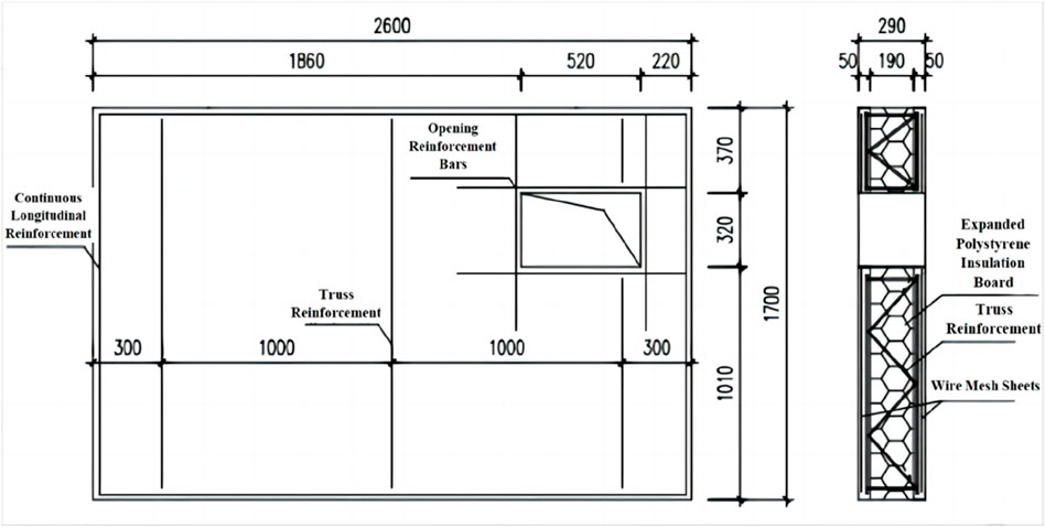
Figure 1. Design illustration of the insulation wall panel.
2.3 Insulation wall cubic specimens
To obtain the bonding strength between finish tiles and wall panels at different stages of the experimental process and analyze their variation patterns, synchronous test blocks were tested during the weathering resistance test. At each stage of the experiment, samples of the finish tiles were taken out for testing without damaging the wall panel specimen. Although the bonding strength obtained by this method may not entirely represent the overall changes in the wall panel, it can significantly reflect the damage to the material and interface strength caused by the experimental conditions. Nine sets of sandwich insulation cubic specimens with pasted finish tiles were produced, with dimensions of 200 mm × 200 mm × 290 mm. Except for the absence of truss reinforcement, the procedures for each layer were consistent with the insulation wall panel. The testing block specimen is shown in Figure 2. It is noted that except for the surface covered by finishing tiles, both sides of the other surfaces were coated with waterproof material. This step ensures that moisture only enters from the external finish surface during the test period, making it more representative of the conditions affecting the wall panel.
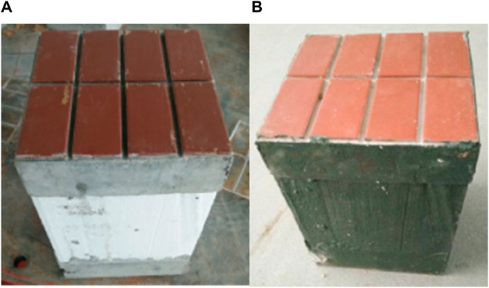
Figure 2. Insulation wall cubic specimens: (A) before waterproof treatment and (B) after waterproof treatment.
2.4 Construction of the wall panel
2.4.1 Reverse attachment of finishing tiles
The traditional method of applying finishing tiles involves bonding them to the concrete wall using mortar, and the construction quality is significantly influenced by the skill level of the workers. Regardless of whether the bond between the mortar and the wall or between the mortar and the facing tile is compromised, it can result in the detachment of finishing tiles, therefore posing safety risks. In this experiment, the technique of reverse attachment of finishing tiles was adopted in the wall panel. This involves arranging the finishing tiles at the bottom of the formwork and then directly pouring concrete to integrate them. This method offers advantages such as a smooth surface, secure adhesion, and efficiency regarding time and labor.
2.4.2 Production of the outer wall
As shown in Figure 3, the pre-bound wire mesh and truss reinforcement was placed into the wall panel mold. It is recommended to add small spacers for proper positioning. The concrete was poured starting from the side with finishing tiles, manually controlling the thickness and smoothing the surface.
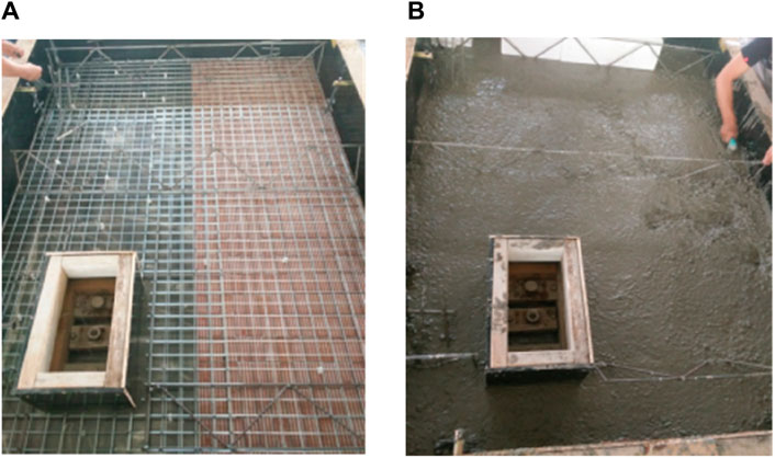
Figure 3. The outer wall production. (A) Placement of wire mesh and truss reinforcement; (B) Pouring of concrete and smoothing.
2.4.3 Placement of EPS insulation board
The openings for embedded parts were reserved. The pre-cut and arranged EPS insulation boards were inserted, and manually compacted and pressed tightly, as shown in Figure 4.
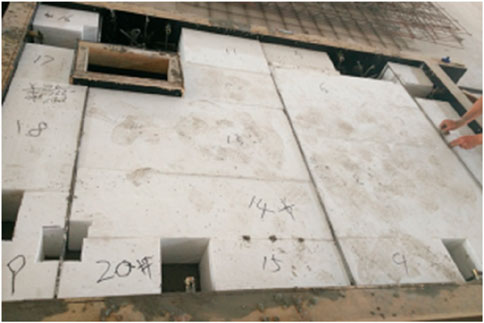
Figure 4. Installment of the insulation board.
2.4.4 Production of the inner wall
The inner wall wire mesh and the embedded parts for wall panel installation were inserted. The wire mesh was properly bound with the truss reinforcement, then the concrete was poured and the surface was smoothed, as shown in Figure 5.
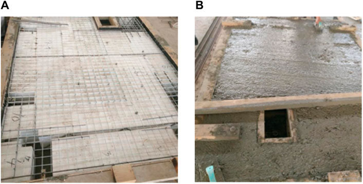
Figure 5. Installment of the insulation board. (A) Placement of wire mesh and embedded parts; (B) Pouring of concrete and smoothing.
2.4.5 Curing of the wall panel
Given the small size of the wall panel specimens in this study, manual steam curing was adopted, which was divided into four stages, namely, pre-curing (30°C for 2 h), temperature rise for 2 h (heated at a rate of 15°C/h until reaching a constant temperature of 65°C), constant temperature for 3 h, and temperature reduction for 4 h. Additionally, to mitigate the adverse effects of steam curing on concrete, the specimens were subjected to supplementary curing, i.e., covered with a film for 48 h.
2.4.6 Demolding and hoisting the wall panel
As shown in Figure 6, the wall panel mold was removed, and the wall panel was lifted horizontally using a crane. The insulation boards were placed at both ends of the wall panel after demolding. Then the wall panel was lifted vertically and positioned on the wall panel supports.
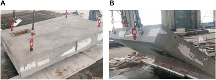
Figure 6. Hoisting and installment of the wall panel. (A) Horizontal lifting of the wall panel; (B) Vertical hoisting of the wall panel.
2.4.7 Installation of the wall panel
The sandwich insulation wall panel was secured to the base wall using expansion bolts around the perimeter of the test base. The gaps between the inner leaf of the test wall panel and the surrounding base wall were filled with adhesive to prevent unnecessary moisture from affecting the test results. The installed wall panel and instruments are depicted in Figure 7, with the test wall panel positioned inside the box for the next steps of the test.
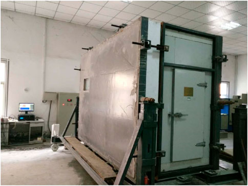
Figure 7. The wall panel and testing equipment after installation.
2.5 Weathering resistance tests of the sandwich insulation wall panel
2.5.1 Weathering test protocol
Thermal-rain cycling was conducted for a total of 80 cycles, with each cycle lasting 6 h. The sample temperature was raised to (70 ± 5)°C within 1 h and maintained for 2 h in an environment with a temperature of (70 ± 5)°C and relative humidity of 10%–30%. Then water spraying was performed for 1 h at a water temperature of (15 ± 5)°C, with each wall panel sample sprayed with a volume of (1.0 ± 0.1) L/(m2·min), followed by a 2-h resting period. Thermal-cold cycling was conducted for a total of 5 cycles, with each cycle lasting 24 h. The specimen temperature was raised to (50 ± 5)°C within 1 h and maintained for 7 h in an environment with a temperature of (50 ± 5)°C and a maximum relative humidity of 30%. Then the sample temperature was lowered to (−20 ± 5)°C within 2 h and maintained for 14 h in an environment with a temperature of (−20 ± 5)°C. Freeze-thaw cycling was performed for 30 cycles, with each cycle lasting 8 h. Water was sprayed for 1 h at a water temperature of (15 ± 5)°C, with each wall panel sample sprayed with a volume of (1.0 ± 0.1) L/(m2·min). The sample temperature was maintained for 1 h at a temperature of (20 ± 5)°C. The sample temperature was lowered to −20°C within 1 h and maintained for 4 h in an environment with a temperature of (−20 ± 5)°C. The sample temperature was raised to 20°C within 0.5 h. Finally, the sample was left to rest for 0.5 h.
2.5.2 Strain monitoring scheme of the wall panel
To monitor the strain variations at different locations of the sandwich thermal insulation wall panel throughout the entire experiment (Hou et al., 2019a), strain gauges were affixed to the concrete surface of the external leaf wall, as illustrated in Figure 8. Positions 1, 6, and 7 were primarily designated for detecting strains near the window openings. Positions 2 and 4 were located on the concrete outside the truss steel bars, position 3 was in the concrete be tween two truss steel bars, and positions 2 and 8 were at different locations on the same truss steel bar. These positions were mainly utilized to analyze the stress impact of truss steel bars on the external leaf concrete. This approach aimed to analyze the strain variations at different positions and different cycle counts, providing a microscopic perspective on the structural deformation characteristics of the wall panel.

Figure 8. Illustration of strain gauge positions.
2.5.3 Loading procedures
2.5.3.1 Thermal rain cycle: 80 cycles, each lasting 6 h
Elevate the sample temperature to (70 ± 5)°C within 1 h, maintaining it in an environment of (70 ± 5)°C and relative humidity of 10%–30% for 2 h; spray water for 1 h at a temperature of (15 ± 5)°C, with each wall panel receiving water at a rate of (1.0 ± 0.1) L/(m2·min); then allow a 2-hour rest.
2.5.3.2 Thermal cold cycle: 5 cycles, each lasting 24 h.
Increase the sample temperature to (50 ± 5)°C within 1 h, maintaining it in an environment of (50 ± 5)°C and maximum relative humidity of 30% for 7 h; decrease the sample temperature to (−20 ± 5)°C within 2 h, maintaining it in an environment of (−20 ± 5)°C for 14 h.
2.5.3.3 Freeze-thaw cycle: 15 cycles, each lasting 8 h
Water the sample for 1 h at a temperature of (15 ± 5)°C, with each wall panel receiving water at a rate of (1.0 ± 0.1) L/(m2·min); maintain the sample temperature at (20 ± 5)°C for 1 h; decrease the sample temperature to −20°C within 1 h, maintaining it in an environment of (−20 ± 5)°C for 4 h; increase the sample temperature to 20°C within 0.5 h; allow it to stand for 0.5 h.
2.5.4 Observation and records during the test
After the thermal rain cycle was completed, a thermal-cold cycle was initiated 2 days later. A freeze-thaw cycle was conducted 2 days later as well. After every 4 thermal rain cycles, every 5 thermal-cold cycles, and every 3 freeze-thaw cycles, observations were made regarding changes such as surface cracks, powdering, hollowness, peeling, etc. The locations and dimensions of these changes were recorded. The specimens were divided into 9 groups, each consisting of 5 blocks. Samples were retrieved before the start of the test (0 cycles), after 28, 56, and 80 thermal rain cycles, after 2 and 5 thermal-cold cycles, and after 3, 9, and 15 freeze-thaw cycles. After 7 days of static adjustment, the tensile bond strength between the facing bricks and concrete was tested. Following the completion of the experiment, the insulation wall panel were left in place for 7 days. Based on the visual inspection, tensile bond strength measurements were conducted in accordance with JGJ110-2008 “Test Standard for Bond Strength of Facing Bricks in Building Construction.”
2.6 Simulation of weathering resistance tests of the panel
The numerical simulation of the nonlinear surface temperature field and temperature stress was conducted using the finite element simulation software ABAQUS. Sequential coupled thermal-stress analyses was required, which involved the initial separate analyses of the heat conduction issue. Subsequently, the temperature field distribution was used as a known load for stress analyses. In addition, the temperature variation values on the surface of the wall panel, collected by the computer during the experimental process, were imported into the model as known conditions.
3 Results and discussion
3.1 Temperature and cracking of the sandwich insulation wall panel
The temperature curves of the wall panel’s outer surface during one cycle of hot-rain and hot-cold cycles obtained from temperature sensor data are depicted in Figures 9, 10.
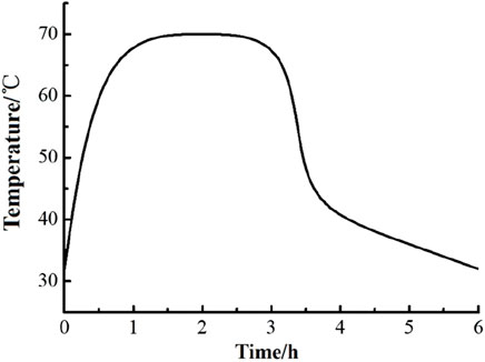
Figure 9. Thermal-rain cycle temperature loading curve.
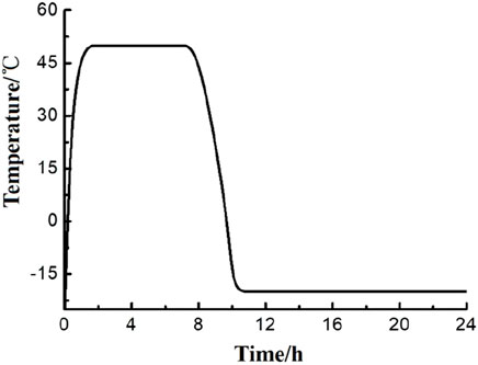
Figure 10. Thermal-cold cycle temperature loading curve.
During the hot-rain cycle, some visible small cracks appeared on the surface of the wall panel. However, the cracks did not show significant growth in length and width, and no water-seeping cracks occurred. No noticeable concrete cracks were observed after manually peeling off the coating putty layer at the location of the small cracks. Therefore, the conclusion can be drawn that throughout the entire weathering test, there were no apparent changes such as water seepage cracks, powdering, hollowing, peeling on the surface of the wall panel. No issues like the detachment of facing bricks or other safety concerns occurred. The wall panel passed the inspection of the weathering test, indicating good weathering performance.
The cracks on the outer surface of the wall panel are mostly shrinkage cracks generated by the high-temperature water spraying of the putty layer, and this is closely related to the quality of materials and construction. In actual construction, it is necessary to control construction quality, and the use of sprayed granular coatings should be considered to enhance the durability of the external finish. Therefore, representative crack positions and directions were selected for summary, and corresponding cracks were surveyed, as shown in Figure 11.
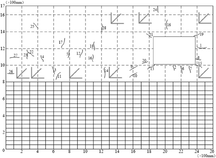
Figure 11. Illustration of cracks distribution.
Cracking distribution can be summarized as follows. Overall, the cracks were relatively short and fine, with no significant trend in length and width growth. The crack development was stable, with no water seepage, indicating that the cracks in the wall panel were harmless, and they did not affect the safety performance and normal use of the wall panel. The locations with more cracks were near windows where stress concentration was prone, and there were more cracks in the middle than in the upper part, mainly because the middle received a larger and more sufficient amount of sprayed water. The cracks on the left and right sides of the wall panel were mainly horizontal, while those on the upper and lower sides were mainly vertical. Diagonal cracks mainly appeared near the corners. There were more vertical cracks in the middle part, and cracks on the left side of the wall panel appeared later and were fewer, mainly near the opening of the box on the left side, where temperature fluctuations and sprayed water were relatively less. In the initial stage, the cracks grew rapidly, but in the later stage, the growth slowed down, and deformation basically stopped. Cracks were more densely distributed in locations with larger water amounts than in locations with less water. There was no significant change in cracks after entering the hot-cold cycle. Therefore, it could be inferred that rainfall had a significant impact on the durability performance of the wall panel.
3.2 Strain analyses under weathering test conditions
Based on the theoretical foundation of temperature effects, it is known that the thermal deformation and thermal stress at any point inside a solid do not directly correspond. The deformation of the wall panel under temperature action is formed by the combined effects of the wall panel’s free expansion (or contraction) during temperature changes, expansion (or contraction) caused by surrounding constraints, and deformation caused by uneven surface temperature distribution.
3.2.1 Strain analyses under thermal-rain cycles
3.2.1.1 Strain comparison at different locations on the outer surface of the wall during the same cycle
To analyze the strain characteristics at different positions during the same cycle, the strain values at each point in the 16th cycle of the thermal rain cycle were taken, and the strain-tim relationship curve was obtained, as shown in Figure 12.
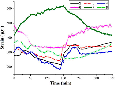
Figure 12. Strain-time curve of each point during thermal-rain cycle of 16 times.
It was found that the strain at each point changed significantly during the 0–60 min heating stage. During the 60–180 min high-temperature constant stage, the strain at each point did not completely stop changing but continued to change with slight fluctuations in temperature. During the 180–240 min water-spraying stage, the temperature dropped sharply, and the strain at each point also changed sharply. During the 240–360 min drying stage, the strain continued to change but with a smaller amplitude. Tensile strain showed in position 7 with the increase in temperature and compressive strain with the decrease in temperature, while the other points showed the opposite trend. Compressive strain occurred during the heating stage and tensile strain during the cooling stage. It can be seen that, unlike the thermal expansion and contraction deformation of external thermal insulation wall panel in the past, the total strain at some positions on the outer surface of this sandwich insulation wall panel showed thermal contraction and cold expansion. Since the deformation of the wall panel under temperature action is determined by both temperature difference and constraints (constraints of the entire wall panel and mutual constraints between different parts of the wall panel), during the heating stage, the wall panel underwent free deformation, resulting in tensile strain.
3.2.1.2 Strain comparison at the same location on the outer surface of the wall panel after different numbers of cycles
To analyze the influence of different numbers of cycles on the concrete strain, strain curves at position 8 in the 1st, 20th, 40th, 60th, and 80th thermal rain cycles were taken, as shown in Figure 13. It was found that in the 1st thermal rain cycle, at the beginning of the test, the heating instrument inside the box had just started working, and the temperature rise process had not reached a relatively uniform and stable state compared to later cycles. Therefore, the initial fluctuation was relatively large, but the overall trend was consistent. In addition, the strain growth during the first 20 cycles was significant, and after 20 cycles, the strain continued to increase, but the growth rate was very small, and the deformation amplitude decreased with more cycles. This indicates that the strain and deformation at this location mainly occurred in the early cycles, and there was residual strain and deformation at the end of each cycle, continuously accumulating to produce plastic deformation. Point 8 was located at the upper part of the wall panel. During the initial temperature rise, this location experiences thermal expansion, but it was then constrained, and the expansion cannot proceed freely, resulting in compressive stress. However, its deformation was influenced and constrained by the surrounding concrete and window openings, showing fluctuating changes. In the high-temperature stage, the final trend was still dominated by expansion being restricted, with the concrete under compression. Conversely, in the later cooling stage, the concrete undergoes tension, and its changes are much smoother than in the heating stage.
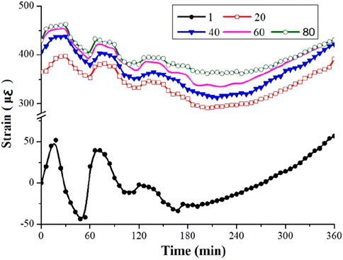
Figure 13. Strain-time curve of position 8 at different times of the thermal-rain cycle.
3.2.2 Strain analyses under thermal-rain cycles
3.2.2.1 Strain comparison at different locations on the outer surface of the wall during the same cycle
The strain analyses was conducted on points 3, 6, 7, and 8 on the outer surface of the wall panel during the third cycle of thermal-cold cycles. The strain-time relationship curve is shown in Figure 14. It was found that each point exhibited a consistent trend of strain variation with the thermal-cold cycle, changing periodically along with the temperature curve. During the 0–1-hour heating phase, significant strain changes occurred at all points. In the 1–8-hour high-temperature constant phase, the strain at each point did not completely cease; initially, it continued to change with minor temperature fluctuations and later tended to stabilize with increasing time. In the 8–10-hour cooling phase, a rapid temperature drop resulted in a sharp change in strain at all points. In the 10–24-hour low-temperature constant phase, strain continued to change but with a smaller amplitude, and later, strain almost ceased to change. Point 6 exhibited the largest amplitude and maximum strain value among all measured points, with the greatest changes during the heating and cooling phases. This point is located at the corner near the window, constrained by the edge of the wall panel and the middle of the truss reinforcement. Therefore, during the heating and high-temperature phases, the concrete expansion is significantly constrained, leading to compressive strain. In the cooling and low-temperature phases, the concrete shrinkage is restricted, resulting in a tensile state, and the residual strain after one cycle reaches 150 με. At point 7, there is an accumulation of compressive strain during thermal-cold cycles, which may contribute to the healing of fine cracks. The deformation trends at points 3, 6, and 8 are relatively consistent, with point 3 exhibiting the smallest change and point 6 the largest.
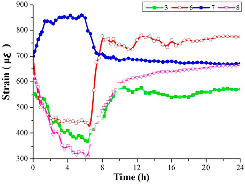
Figure 14. Strain-time curve of each point during 3 thermal-cold cycles.
3.2.2.2 Strain comparison at the same location on the outer surface of the wall panel after different numbers of cycles
To analyze the impact of different cycle numbers on concrete strain, the strain curves for the 1st, 3rd, and 5th thermal-cold cycles at point 8 are shown in Figure 15. It was observed that the initial temperature of the 1st thermal-cold cycle was the same as room temperature, while the subsequent cycles were continuous and started from −20°C. Therefore, during the heating phase, the strain values in the first cycle changed significantly less than in the later cycles, and the later trends were basically consistent. In addition, the strain growth during the 1st cycle was relatively large, and after the 3rd and 5th cycles, the strain values continued to increase, but the growth rate was significantly smaller. Additionally, with more cycles, the deformation amplitude decreased. The distance between the 5th and 3rd cycles was noticeably smaller than that between the 1st and 3rd cycles. This indicates that strain and deformation primarily occur in the early cycles and accumulate certain plastic deformation.
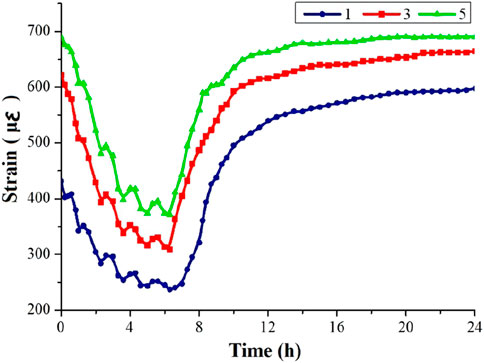
Figure 15. Strain-time curve at position 8 during different times of thermal-cooling cycles.
3.3 Tensile bond strength of the test blocks
Prior to the experiment (0 cycles), specimens were subjected to 28, 56, and 80 cycles of hot-rain, 2 and 5 cycles of hot-cold, and 3, 9, and 15 cycles of freeze-thaw. Afterward, the specimens were retrieved and allowed to settle in a quiescent state for 7 days, and then tested for the tensile bond strength between facing bricks and concrete. As can be seen in Figure 16, the bond strength of facing bricks decreased by 8.1% following the completion of the hot-rain cycles, after the hot-cold cycles, it decreased by 5.1%, and after the freeze-thaw cycles, it decreased by 12.1%. Overall, the reduction in bond strength was not substantial. In comparison, the freeze-thaw cycles had the most significant impact, followed by the hot-rain cycles, while the hot-cold cycles had the least effect. This can be attributed primarily to moisture infiltration, leading to inadequate dissipation of thermal and moisture-induced stresses. The interface between facing bricks and concrete experienced freeze-thaw cycles, resulting in a certain degree of reduction in bond strength.
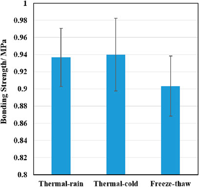
Figure 16. Bonding strength of the testing blocks under three cycles.
3.4 Simulations for stress and deformation analyses
The calculation of temperature-induced stresses employed sequential coupled thermal stress analyses. The temperature field data obtained from the analysis were loaded into the model to solve for stress and strain. The stress and displacement of the wall panel under temperature effects are closely related to the constraints it experiences. In the experiment, the wall panel was connected to the base wall using angle steel and bolts. Due to the focus on analyzing the external surface of the wall panel in the weathering test, constraints were simplified by treating them as hinged with additional steel plates. The mesh division and constraint conditions are illustrated in Figure 17.
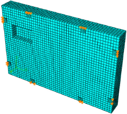
Figure 17. Finite element model for stress field analysis of the wall panels.
3.4.1 Stress and deformation analyses under thermal-rain cycles
3.4.1.1 Wall panel stresses
The obtained S11 and S22 in the simulation represent the stress distribution along the length and width directions of the wall panel, as shown in Figure 18. In the S22 graph, it was assumed that there was no window opening in the upper right corner of the wall panel, the model should be symmetrical, and under the influence of uniformly distributed temperature, the stress distribution on both sides should be relatively consistent. However, small tensile stresses appear on both sides of the window opening in the model, with a significant area of higher tensile stress below the opening. It can be inferred that the opening has a significant impact on the distribution of temperature-induced stresses. In S22, the left half of the wall panel from the constrained position to the vicinity of the truss steel reinforcement showed noticeable compressive stresses. The right half of the wall panel, except for the lower part of the window opening (considered as influenced by the window opening), also exhibited significant compressive stresses at the constrained and truss steel reinforcement positions. This indicates that both the truss steel reinforcement and bolt constraints had a pronounced restraining effect on the wall panel’s expansion deformation during the high-temperature stage, resulting in a state of constrained expansion and compression. This is consistent with the conclusions drawn from the earlier analysis of strain variations in the experiment. The middle position of the wall panel still showed a tensile state. The concrete constraints at the middle position are relatively small, and the compressive forces on both sides of the concrete also indirectly induced tensile stresses. Thus, even though there is tension in the truss steel reinforcement at the middle part of this wall panel, its effect on altering the concrete stress state was minimal. Combining the S11 and S22 graphs, it can be seen that during the temperature rise stage, the upper half of the wall panel was mostly subjected to compression, with a certain area near the window opening showing tension. This aligns with the observed strain variations during the experiment, where position 7 near the window opening experienced tension during the high-temperature stage, while other positions were under compression.
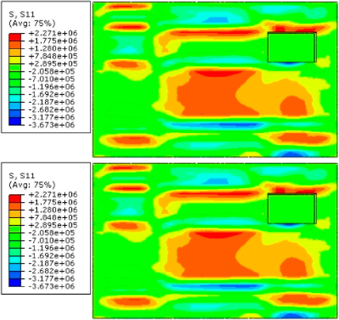
Figure 18. Finite element model for stress field analysis of the wall panels.
Figure 19 shows the distribution of the maximum principal stress in the entire concrete wall panel. Typically, the maximum principal stress is used to assess the cracking of brittle materials such as concrete. It can be observed that the maximum principal stress in the inner leaf wall was distributed in a ring shape, following the positions constrained by the surroundings. However, the external leaf wall was less affected by the constraints from the surroundings. The uneven distribution of temperature-induced stresses in the external leaf wall is evident, with red areas indicating tensile stresses with relatively large values, and blue areas indicating the transition from tensile to compressive stresses. This suggests a significant mutual inhibitory effect of temperature stresses at various positions on the deformation of the nearby concrete. Overall, areas with larger regions of tensile stresses were found in the middle and lower parts of the window, thus indicating a higher risk of concrete cracking in these regions.
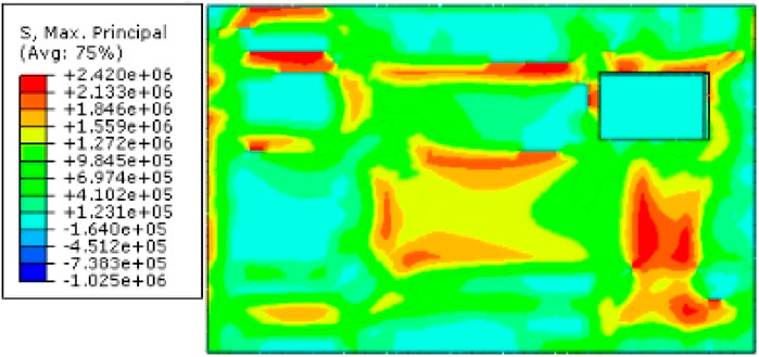
Figure 19. Principal stress distribution diagram of the wall panel during high temperature stage.
3.4.1.2 Deformation of the wall panel
Finite element simulation results for the deformation and displacement of the wall panel during the high-temperature stage are shown in Figure 20. Along the thickness direction of the wall panel, it can be observed that during the expansion deformation caused by temperature rise, the deformation of the wall panel was significantly constrained at the positions with truss steel reinforcement in the length direction of the wall panel. However, in the height direction of the wall panel, where there was no tensile reinforcement, no similar phenomenon occurs. Therefore, it can be seen that the tensile reinforcement effect of the truss steel restricts the free deformation of the wall panel, ensuring that the three parts of the wall panel behave as a whole. In addition, the constraints from bolts around the perimeter mainly restricted the deformation of the inner leaf wall, while the deformation of the outer leaf wall was relatively free. Notably, the overall behavior of the wall panel showed maximum displacement in the middle-upper part, gradually decreasing from the center to the sides, with an overall displacement ranging from 0.67 to 1.6 mm.
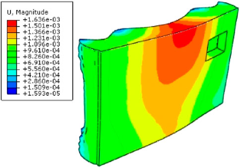
Figure 20. Wall panel deformation and displacement diagram at high temperature stage.
3.4.2 Stress and deformation analyses under thermal-cold cycles
The temperature effects during the high-temperature stage of the thermal-cold cycle are consistent with the temperature actions during the thermal-rain cycle, and are not reiterated here. This section specifically analyzes the low-temperature stage (−20°C) during the hot-cold cycle. The simulated results of the plane stress, maximum principal stress, displacement, and deformation are illustrated in Figures 21–23, respectively.
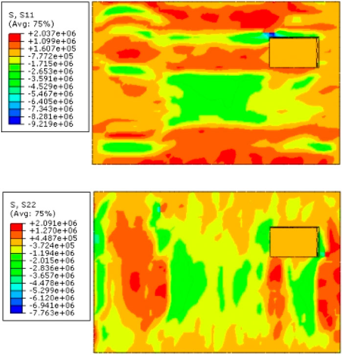
Figure 21. Plane stress in the low-temperature stage of the thermal-cold cycle.
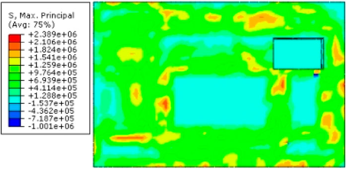
Figure 22. Principal stress distribution diagram of the wall panel at low temperature stage.
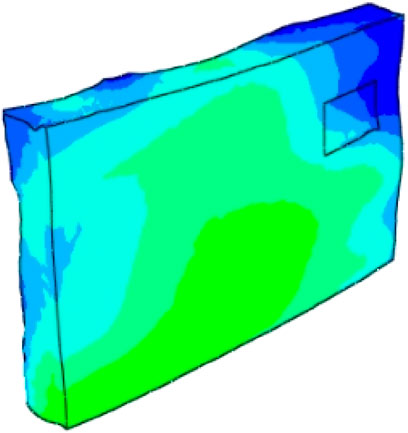
Figure 23. Wall panel deformation and displacement diagram at low temperature stage.
It was found that in contrast to the stress state of concrete during the high-temperature stage, the left half of the wall, from the constrained position to the vicinity of the truss steel, exhibited significant tensile stress. The right half of the wall, except for the lower part of the window opening, was in a compressive state (attributed to the influence of the window opening), and also in a tensile state at the constrained and truss steel locations. This indicates that during the contraction deformation of the wall in the low-temperature stage, both truss steel and bolts had a notable constraining effect, resulting in restrained contraction and a tensile state. In addition, the middle part of the wall is mainly in a compressive state, gradually changing to a tensile state towards the upper and lower sides. Combining the S11 and S22 graphs, during the temperature decrease stage, the upper part of the wall is mostly in tension, with the concrete being compressed at the upper-left corner of the window. This is consistent with the earlier experimental strain change conclusions. Also, the middle part and the area below the window of the wall have principal stresses smaller than those in the surrounding regions. Overall, the likelihood of cracking in the winter low-temperature climate is much smaller than in the hot summer climate. Notably, In the low-temperature stage, the wall did not exhibit significant deformation compared to the high-temperature stage, and the displacement mostly ranged from 0.55 to 0.63 mm.
4 Conclusion
This paper focuses on exploring weathering resistance of a novel prefabricated EPS sandwich insulation wall panel with irregular column frame structures. The study involves comprehensive analyses of weather resistance and stress characteristics through visual inspections of the panel, determination of the bond strength of facing bricks, and analyses of strain data. Additionally, finite element analysis software ABAQUS was employed to simulate and analyze the temperature effects under weathering test conditions. The conclusions drawn from the study are as follows.
(1) In the weathering test, the panel surfaces did not exhibit apparent water seepage cracks, powdering, hollowing, peeling, etc. There was no occurrence of facing brick detachment or damage. This indicates that the tested wall panels passed the inspection of weathering tests, demonstrating good weather resistance. The strain variation patterns of the wall panels were analyzed at various locations and cycles. The data revealed the impact of the tensile reinforcement of the framework steel and the constraints from the surroundings. The outer surface concrete of the wall panel exhibited resistance during typical thermal expansion and contraction, resulting in compressive stress during expansion and tensile stress during contraction.
(2) The bond strength of the specimens decreased by 8.1% after the thermal-rain cycles, 5.1% after the thermal-cold cycles, and 12.1% after the freeze-thaw cycles, with concrete being the primary mode of failure. It is evident that the reduction in bond strength is not significant. In contrast, the freeze-thaw cycles had the most substantial impact, followed by the thermal-rain cycles, while the thermal-cold cycles had the smallest effect. This is mainly attributed to the entry of moisture, resulting in thermal and moisture-induced stresses and the loss of bond strength due to freeze-thaw cycles at the interface.
(3) The temperature effects on the wall panel under weathering conditions were simulated using ABAQUS. During the expansion deformation of the wall panel in the high-temperature phase, the restraint from the truss reinforcement and bolts significantly constrained it, resulting in restrained expansion and a compressive state. Conversely, during the contraction deformation in the low-temperature phase, it exhibited restrained contraction and a tensile state. It is evident that the results of numerical simulation using the finite element method for nonlinear surface temperature effects were reliable.
(4) In the numerical simulation, the temperature stress at various positions on the concrete wall had a noticeable mutual restraining effect on the force deformation of the nearby concrete. There was a significant risk of cracking in the middle and around the opening, particularly in the lower part of the wall panel. During the high-temperature phase of the thermal rain cycle, the overall deformation of the wall panel was characterized by maximum displacement in the upper-middle section. However, during the low-temperature phase of the thermal-cold cycle, the wall panel did not exhibit significant deformation observed during the high-temperature phase.
5 Future research suggestions
(1) In addition to temperature variations, loads and water spraying, factors such as solar radiation intensity, duration of water spraying, and the content of eroding impurities in the water can also influence the external surface of the wall panel. If these factors can be taken into account in weather resistance tests, the results will be more realistic, enhancing the credibility of the experimental outcomes.
(2) Regarding this novel prefabricated concrete sandwich insulation wall panel with irregular column frame structures itself, different thicknesses and materials of concrete could be investigated to identify the most suitable external wall material and thickness, therefore ensuring both durability and safety.
Data availability statement
The original contributions presented in the study are included in the article; further inquiries can be directed to the corresponding author.
Author contributions
JW: Writing–original draft, Investigation. SP: Conceptualization, Writing–review and editing. SJ: Investigation, Software, Writing–review and editing. XL: Data curation, Methodology, Writing–review and editing. LW: Supervision, Validation, Writing–original draft. JZ: Funding acquisition, Writing–review and editing.
Funding
The author(s) declare that financial support was received for the research, authorship, and/or publication of this article. The research work was supported by CSCEC-PT-015CSCEC City Renovation and Intelligent Operation Engineering Research Center (Building Health Diagnosis and Treatment).
Acknowledgments
The authors would like to acknowledge the support provided by Hebei University of Technology for guidance and greatly appreciate for providing the research facilities.
Conflict of interest
Authors JW, SP, SJ, and XL were employed by Beijing Building Research Institute Corporation Ltd. of China State Construction Engineering Corporation. Author LW was employed by China Construction First Group Corporation Ltd.
The remaining author declares that the research was conducted in the absence of any commercial or financial relationships that could be construed as a potential conflict of interest.
Publisher’s note
All claims expressed in this article are solely those of the authors and do not necessarily represent those of their affiliated organizations, or those of the publisher, the editors and the reviewers. Any product that may be evaluated in this article, or claim that may be made by its manufacturer, is not guaranteed or endorsed by the publisher.
References
Abergel, T., Dean, B., and Dulac, J. (2017) Towards a zero-emission, efficient, and resilient buildings and construction sector: global Status Report 2017. Paris, France: UN Environment and International Energy Agency.
Asan, H. J.,(2000). Investigation of wall's optimum insulation position from maximum time lag and minimum decrement factor point of view. Energy Build. 32 (2), 197–203. doi:10.1016/s0378-7788(00)00044-x
Axaopoulos, I., Axaopoulos, P., Gelegenis, J., and Fylladitakis, E. D. J. J. o.B. P. (2019). Optimum external wall insulation thickness considering the annual CO2 emissions. J. Build. Phys. 42 (4), 527–544. doi:10.1177/1744259118774711
Aye, L., Ngo, T., Crawford, R. H., Gammampila, R., and Mendis, P. (2012). Life cycle greenhouse gas emissions and energy analysis of prefabricated reusable building modules. Energy Build. 47, 159–168. doi:10.1016/j.enbuild.2011.11.049
Balocco, C., Grazzini, G., and Cavalera, A. J. E. (2008). Transient analysis of an external building cladding. Energy Build. 40 (7), 1273–1277. doi:10.1016/j.enbuild.2007.11.008
Cai, M., Chen, S., Tang, Y., Li, Q., and An, W. J. C. S. i.T. E., Study on the influence of enclosed vertical channels on downward flame spread over XPS thermal insulation materials, , 14 (2019) 100486, doi:10.1016/j.csite.2019.100486
Cao, X., Li, X., Zhu, Y., and Zhang, Z. (2015). A comparative study of environmental performance between prefabricated and traditional residential buildings in China. J. Clean. Prod. 109, 131–143. doi:10.1016/j.jclepro.2015.04.120
Choi, I., Kim, J., and Kim, H.-R. J. M., Composite behavior of insulated concrete sandwich wall panels subjected to wind pressure and suction, , 8(3) (2015) 1264–1282. doi:10.3390/ma8031264
Choi, I., Kim, J., and You, Y.-C. J. C. P. B. E., Effect of cyclic loading on composite behavior of insulated concrete sandwich wall panels with GFRP shear connectors, , 96 (2016) 7–19. doi:10.1016/j.compositesb.2016.04.030
Daniotti, B., Paolini, R., and Re Cecconi, F. J. D. o.B. M., Effects of ageing and moisture on thermal performance of ETICS cladding, (2013) 127–171. doi:10.1007/978-3-642-37475-3_6
Dickson, T., and Pavía, S. (2021). Energy performance, environmental impact and cost of a range of insulation materials. Renew. Sustain. Energy Rev. 140, 110752. doi:10.1016/j.rser.2021.110752
Goodier, C., and Gibb, A. (2007). Future opportunities for offsite in the UK. Constr. Manag. Econ. 25 (6), 585–595. doi:10.1080/01446190601071821
Hassan, T. K., and Rizkalla, S. H. J. P. J. (2010). Analysis and design guidelines of precast, prestressed concrete, composite load-bearing sandwich wall panels reinforced with CFRP grid. pcij. 55 (2), 147–162. doi:10.15554/pcij.03012010.147.162
Hong, J., Shen, G. Q., Li, Z., Zhang, B., and Zhang, W. (2018). Barriers to promoting prefabricated construction in China: a cost–benefit analysis. J. Clean. Prod. 172, 649–660. doi:10.1016/j.jclepro.2017.10.171
Hou, H., Ji, K., Wang, W., Qu, B., Fang, M., and Qiu, C. (2019a). Flexural behavior of precast insulated sandwich wall panels: full-scale tests and design implications. Eng. Struct. 180, 750–761. doi:10.1016/j.engstruct.2018.11.068
Hou, H., Ji, K., Wang, W., Qu, B., Fang, M., and Qiu, C. J. E. S. (2019b). Flexural behavior of precast insulated sandwich wall panels: full-scale tests and design implications. Eng. Struct. 180, 750–761. doi:10.1016/j.engstruct.2018.11.068
Jaillon, L., and Poon, C. S. (2008). Sustainable construction aspects of using prefabrication in dense urban environment: a Hong Kong case study. Constr. Manag. Econ. 26 (9), 953–966. doi:10.1080/01446190802259043
Jaillon, L., and Poon, C. S. (2009). The evolution of prefabricated residential building systems in Hong Kong: a review of the public and the private sector. Automation Constr. 18 (3), 239–248. doi:10.1016/j.autcon.2008.09.002
Jiang, L., Li, Z., Li, L., and Gao, Y. J. S. (2018). Constraints on the promotion of prefabricated construction in China. Sustainability 10 (7), 2516. doi:10.3390/su10072516
Kon, O., and Caner, İ. J. B. (2022). The effect of external wall insulation on mold and moisture on the buildings. Build. (Basel). 12 (5), 521. doi:10.3390/buildings12050521
Lafond, C., and Blanchet, P. J. B. (2020). Technical performance overview of bio-based insulation materials compared to expanded polystyrene. Build. (Basel). 10 (5), 81. doi:10.3390/buildings10050081
Lakatos, Á., and Kovács, Z. J. E. (2021). Comparison of thermal insulation performance of vacuum insulation panels with EPS protection layers measured with different methods. Energy Build. 236, 110771. doi:10.1016/j.enbuild.2021.110771
Lawson, R., and Ogden, R. (2010). “Sustainability and process benefits of modular construction,” in Proceedings of the 18th CIB World Building Congress, Salford, UK, 10–13.
Li, H., Guo, H., Skitmore, M., Huang, T., Chan, K., and Chan, G. (2011). Rethinking prefabricated construction management using the VP-based IKEA model in Hong Kong. Constr. Manag. Econ. 29 (3), 233–245. doi:10.1080/01446193.2010.545994
Li, Q., Wei, H., Han, L., Wang, F., Zhang, Y., and Han, S. J. S. (2019). Feasibility of using modified silty clay and extruded polystyrene (XPS) board as the subgrade thermal insulation layer in a seasonally frozen region, northeast China. Sustainability 11 (3), 804. doi:10.3390/su11030804
López-Mesa, B., Pitarch, Á., Tomás, A., and Gallego, T. (2009). Comparison of environmental impacts of building structures with in situ cast floors and with precast concrete floors. Build. Environ. 44 (4), 699–712. doi:10.1016/j.buildenv.2008.05.017
Mahaboonpachai, T., Kuromiya, Y., Matsumoto, T. J. C., and Materials, B. (2008). Experimental investigation of adhesion failure of the interface between concrete and polymer-cement mortar in an external wall tile structure under a thermal load. Constr. Build. Mater. 22 (9), 2001–2006. doi:10.1016/j.conbuildmat.2007.07.002
Mahaboonpachai, T., Matsumoto, T., and Inaba, Y. J. I. J. o.A. (2010). Investigation of interfacial fracture toughness between concrete and adhesive mortar in an external wall tile structure. Int. J. Adhes. Adhes. 30 (1), 1–9. doi:10.1016/j.ijadhadh.2009.06.005
Marincioni, V., Marra, G., and Altamirano-Medina, H. J. B. (2018). Development of predictive models for the probabilistic moisture risk assessment of internal wall insulation. Build. Environ. 137, 257–267. doi:10.1016/j.buildenv.2018.04.001
Martel, T., Rirsch, E., Simmonds, A., and Walker, C. J. C. S. i.C. M., The monitoring of wall moisture in a property retrofitted with Internal Wall Insulation, , 14 (2021) e00520. doi:10.1016/j.cscm.2021.e00520
Meddage, D., Chadee, A., Jayasinghe, M., and Rathnayake, U. J. C. S. i.C. M., Exploring the applicability of expanded polystyrene (EPS) based concrete panels as roof slab insulation in the tropics, , 17 (2022) e01361, doi:10.1016/j.cscm.2022.e01361
Nadim, W., and Goulding, J. S. (2010). Offsite production in the UK: the way forward? A UK construction industry perspective. Constr. Innov. 10, 181–202. doi:10.1108/14714171011037183
Naito, C., Hoemann, J., Beacraft, M., and Bewick, B. (2012). Performance and characterization of shear ties for use in insulated precast concrete sandwich wall panels. J. Struct. Eng. 138 (1), 52–61. doi:10.1061/(asce)st.1943-541x.0000430
O Hegarty, R., and Kinnane, O. J. C. (2020). Review of precast concrete sandwich panels and their innovations. Constr. Build. Mater. 233, 117145. doi:10.1016/j.conbuildmat.2019.117145
Ozel, M. J. E. (2014). Effect of insulation location on dynamic heat-transfer characteristics of building external walls and optimization of insulation thickness. Energy Build. 72, 288–295. doi:10.1016/j.enbuild.2013.11.015
Park, S.-H., Lee, M., Seo, P.-N., and Kang, E.-C. J. B. (2020). Effect of resin content on the physiochemical and combustion properties of wood fiber insulation board. Bioresources 15 (3), 5210–5225. doi:10.15376/biores.15.3.5210-5225
Pons, O., and Wadel, G. (2011). Environmental impacts of prefabricated school buildings in Catalonia. Habitat Int. 35 (4), 553–563. doi:10.1016/j.habitatint.2011.03.005
Qiao, W., Yin, X., Zhang, H., and Wang, D. (2020) Experimental study of insulated sandwich concrete wall connections under cyclic loading, Structures. Amsterdam, Netherlands: Elsevier, 2000–2012.
Rodrigues, L., White, J., Gillott, M., Braham, E., and Ishaque, A. J. E. (2018). Theoretical and experimental thermal performance assessment of an innovative external wall insulation system for social housing retrofit. Energy Build. 162, 77–90. doi:10.1016/j.enbuild.2017.10.020
Sharma, P., and Kumar, V. P. (2023a). Fabrication of a sandwich panel by integrating coconut husk with polyurethane foam and optimization using R2. Constr. Build. Mater. 409, 133929. doi:10.1016/j.conbuildmat.2023.133929
Sharma, P., and Kumar, V. P. (2023b). Amelioration of sandwich panels by replacing polyurethane foam with coconut husk and study on computational prediction using ANN and LR. Innov. Infrastruct. Solutions 8 (12), 331. doi:10.1007/s41062-023-01284-6
Shin, D.-H., and Kim, H.-J. J. J. o.B. E., Composite effects of shear connectors used for lightweight-foamed-concrete sandwich wall panels, , 29 (2020) 101108, doi:10.1016/j.jobe.2019.101108
Sparksman, G., Groak, S., Gibb, A., and Neale, R. (1999) Standardisation and pre-assembly: adding value to construction projects. CIRIA Report 176. London: Construction Industry Research & Information Association.
Tam, V. W., Tam, C. M., Zeng, S., and Ng, W. C. (2007). Towards adoption of prefabrication in construction. Build. Environ. 42 (10), 3642–3654. doi:10.1016/j.buildenv.2006.10.003
Xu, C., Li, S., and Zou, K. J. J. o.B. E., Study of heat and moisture transfer in internal and external wall insulation configurations, , 24 (2019) 100724. doi:10.1016/j.jobe.2019.02.016
Keywords: prefabricated concrete, sandwich insulation wall panel, weathering resistance, temperature effects, concrete
Citation: Wang J, Pang S, Ji S, Li X, Wang L and Zhang J (2024) Weathering resistance of novel sustainable prefabricated thermal insulation wall. Front. Mater. 11:1392372. doi: 10.3389/fmats.2024.1392372
Received: 27 February 2024; Accepted: 27 May 2024;
Published: 17 June 2024.
Edited by:
Yang Zou, Chongqing Jiaotong University, ChinaReviewed by:
Amir Ali Shahmansouri, Washington State University, United StatesV. R. Prasath Kumar, SRM Institute of Science and Technology, India
L. Krishnaraj, SRM Institute of Science and Technology, India
Copyright © 2024 Wang, Pang, Ji, Li, Wang and Zhang. This is an open-access article distributed under the terms of the Creative Commons Attribution License (CC BY). The use, distribution or reproduction in other forums is permitted, provided the original author(s) and the copyright owner(s) are credited and that the original publication in this journal is cited, in accordance with accepted academic practice. No use, distribution or reproduction is permitted which does not comply with these terms.
*Correspondence: Junfei Zhang, junfeizhang@hebut.edu.cn