- School of Electrical and Information Engineering, North Minzu University, Yin Chuan, China
The voltage control performance of the voltage source inverter (VSI) in a microgrid may change under different load conditions. However, in the case of traditional control strategies, the robustness of VSI is insufficient. In response to the above problems, a novel robust control scheme for VSI in the microgrid based on H∞ hybrid sensitivity is proposed in this study. The grid-side interference during the VSI operation is taken as the variable, and the sensitivity function is designed to build a H∞ robust voltage controller for VSI. In addition, an adaptive virtual impedance group is designed to further improve the voltage control robustness under a variety of operation conditions. Finally, comparative simulation experiments are carried out to verify the anti-interference ability of the proposed control strategy under different working conditions.
Introduction
A microgrid is a small power system composed of DGs, loads, energy storage devices, energy conversion devices, and protection devices (Beheshtaein, et al., 2019; Anderson and Suryanarayanan, 2020), which can generally operate in an island mode or a grid-connected mode according to different system conditions (Yang et al., 2014). In the island operation mode, the microgrid bus voltage is regulated by multiple DG units through the joint action of their converters. The island operation mode is more prone to various power quality problems such as voltage deviation, three-phase imbalance voltage (Bouzid et al., 2015; Chen et al., 2021; Xu et al., 2019), and harmonic problem (Zhai et al., 2020; Yi et al., 2014; Wang, et al., 2019). The voltage deviation is mainly caused by the load change in the system (Shokri et al., 2015). The three-phase asymmetric load connected to the microgrid is the main cause of the three-phase voltage imbalance, which leads to increased system losses and malfunctions in the operation of electrical equipment (Shi et al., 2016). The goal is to suppress the voltage deviation of the inverter system; a low-frequency communication recovery voltage control strategy is used by Sun et al. (2016) to compensate for voltage drops that occur in the inverter system. In the work of Rathore et al. (2021), the authors adjusted the output voltage amplitude to compensate for the voltage deviation. In the work of Liu et al. (2017), an adaptive virtual impedance is added to compensate for the difference in voltage drop caused by the transmission line impedance mismatch. Aiming at the problem of island mode voltage imbalance, a negative sequence voltage is injected into the line through a series of power quality regulators (Das et al., 2020). Aiming at the imbalance problem in the control of the microgrid inverter, a variety of control strategies are used to coordinate and suppress the unbalanced voltage in layers (Tian et al., 2016). In the work of Nejabatkhah et al. (2018), the parallel interfacing converters’ control strategy of the parallel hybrid compensation system can effectively suppress the three-phase unbalanced voltage. (Xiongfei Wang et al., 2014) introduced a stable negative sequence virtual impedance compensation method (2014). This compensation strategy needs to separate the positive sequence part and the negative sequence part of the voltage. The dynamic response is mainly affected from the excessively positive and negative sequence separation loops. For this reason, a composite virtual impedance is proposed by Wang et al. (2018) to offset the negative sequence voltage drop caused by the negative sequence current. The harmonic current is mainly caused by the non-linear load, which may further affect the voltage control performance. In this case, the harmonic can be compensated by a special converter such as active power filter (APF) (Zhai et al., 2020; Yi et al., 2014) or can be eliminated by the special control scheme within the inverter (Wang, et al., 2019).
In the traditional droop control strategy, the voltage and current double-loop control in the inverter usually adopts proportional integral control (Sarmiento et al., 2018). However, its robust control performance needs to be further improved while system parameters are perturbed (Bouzid et al., 2015). Most of the improved inverter control algorithms are only for several specific working conditions, and the controller design is complicated and takes up more controller memory.
In industrial controllers, robust controllers can achieve good control performance when there are external disturbances or parameter perturbations in the system. The application of robust controllers in power electronic converters is gradually increasing (Pradhan et al., 2019; Sadabadi et al., 2017), such as AC–DC hybrid microgrid AC–DC section and photovoltaic inverter (Rasekh and Hosseinpour, 2020; Sedhom et al., 2020). There are several research studies on the realization of robust controllers in an inverter (Taher and Zolfaghari, 2014; Lai and Kim, 2018; Pathan, 2020; Dehkordi, 2020). However, the design of sensitivity function and the stable performance need to be studied further, regarding how to select disturbance variables and sensitivity functions reasonably, how to formulate inverter optimization control strategies, and how to design robust control schemes suitably for microgrid VSI. In order to finally improve the stability and dynamic robustness of the voltage inverter in terms of performance, further research is needed. In response to the above problems, a new robust control strategy suitable for microgrid VSI is proposed in this study. Its main purpose is to ensure the steady-state and dynamic robust performance of the VSI under system parameter disturbances and load disturbances.
In this study, a generalized parameter uncertainty model of VSI is constructed based on the mathematical model, disturbance variables, and sensitivity function. According to linear matrix inequality (LMI), a robust H∞ controller is obtained. Meanwhile, a virtual impedance group is designed to further improve the robustness of voltage control.
The Island Microgrid System and Control Strategy
The Structure of the Island Microgrid
In island microgrids, the load power may fluctuate in different time periods. Diesel generators and fuel cells are used to ensure the basic power supply of the island microgrid. Renewable energies (wind energy and photovoltaic) supply power according to the load demand in different time periods and meet the power demand through reasonable planning and forecasting of renewable energy, reducing operating costs (Mazidi et al., 2020).
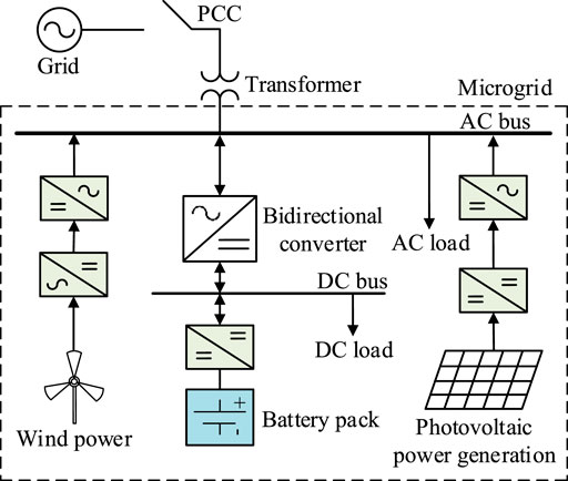
The structure diagram of the microgrid is shown in Figure 1. When the microgrid is disconnected from the grid, it operates in an island mode (Xin et al., 2015). In this mode of operation, power generation equipment and energy storage equipment are used to maintain the stable operation of the microgrid. Energy storage systems, wind power, photovoltaics, and fuel cells need to be connected to the microgrid through inverters. Therefore, improving the control performance of the inverter in the microgrid is an important way to ensure the power supply quality of the microgrid.
The Control Scheme of VSI
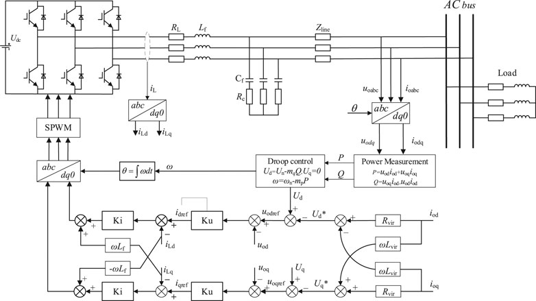
The VSI adopts a three-phase three-wire two-level full-bridge topology. The inverter structure is shown in Figure 2. The output filter of the inverter generally adopts the LC form.
VSI is the core converter in a microgrid, including an active power outer loop, a voltage loop, and a current loop. Reactive power Q and active power P are obtained by calculating the voltage and current (Liu et al., 2019). Then, according to the droop control equations of P-f and Q-U, the frequency reference and voltage reference are calculated. The droop control equation is written as follows:
where Ud and Uq are the reference voltage in the dq frame, ω is reference frequency, ωn is the rated frequency, Un is the rated voltage reference value, and mp and nq are the droop coefficients.
For the purpose of enhancing the power-sharing performance of VSI, a virtual resistance is added to the traditional parallel operation to increase the damping of the system and effectively suppress the oscillation in the system (H. Shi et al., 2016). At the same time, the introduction of virtual inductors improves the accuracy of decoupling control of active and reactive power (Geng et al., 2020; Dheer et al., 2020). The virtual impedance is realized in the dq rotating coordinate system as follows:
Among them, Rvir, Lvir, and ω0 are the virtual resistance, virtual inductance, and the angular frequency of the rotating coordinate, respectively, Ud* and Uq* are the reference output voltage adjustment values of d and q axes, respectively, and iod and ioq are the value of the load current in the dq coordinate system.
The Proposed Robust Voltage Controller for VSI
A General Description of the Robust Control Scheme
Architecture of the H∞ System
The basic framework of robust control is shown in Figure 3A (Bouzid et al., 2016),where, i(t), z(t), y(t), and u(t) are the input signal, the performance evaluation signal, the controller input signal, and the output signal of the controller, respectively; F(s) is the H∞ robust controller, and P(s) is the generalized controlled system.

FIGURE 3. A general description of the robust control scheme. (A) H∞ standard question structure diagram and (B) mixed sensitivity problem of the model.
The transfer function between i(t) and z(t) can be expressed as
To solve the H∞ robust controller is to solve the appropriate F(s) satisfaction,
Mixed Sensitivity Issues
The mixed sensitivity problem contains two issues: the uncertainty of the controller parameters and the restraint effect of the controller on external disturbances (Li et al., 2016). The general structure of the mixed sensitivity function is shown in Figure 3B, where F(s)and G(s) are the H∞ robust controller and the controlled plant, respectively; WS, WR, and WT are weighting functions; and r(t), u(t), y(t), and e(t) are the relative signals in the system and tracking error. Its closed-loop transfer function can be written as follows:
where I is the identity matrix, G is the transfer function of the controlled object, and F is the controller model. The sensitivity function S has an absolute effect on the tracking error of the system. When S is smaller, the tracking performance of the inverter controller is better. The control transport function R limits the size of the control quantity u. The compensation sensitivity function T plays a decisive role in the stability of the system and determines the size of the output quantity. In this case, the choice of features S and T is mutually constrained. A compromise should be considered when selecting. The mixed sensitivity problem is to find the appropriate weighting functions, WS, WR, and WT, and find the appropriate controller F(s) to make the closed-loop control system stable. Eq. 6 is as followed:
where γ is the system performance index.
Mathematical Model of VSI in the Island Microgrid
The structure of VSI in the microgrid is shown in Figure 4, where Udc, uabc, and ucabc are the DC voltage source, inverter voltage, and voltage drop on filter capacitance, respectively; Rf, Rc, Lf, and Cf are LC filter parameters; Lline and Z are wire inductance and the three-phase load, respectively; and iabc and igabc are current flowing through the filter inductor and load current, respectively. According to the above parameters, a mathematical model of the inverter output voltage is established (Liu et al., 2016; Wang et al., 2017). By using the KVL calculation method (Kirchhoff’s law of voltage), the voltage relationship through the inverter can be expressed as follows:
According to the KCL theory (Kirchhoff’s law of current), the relationship of the current flowing through the inverter can be described as follows:
The goal is to enhance the control performance of the VSI system. The parameters are converted from a three-phase AC to DC. The relationship between the output current and output voltage in the system is obtained as follows:
Therefore, the state space model can be obtained as
By replacing Eqs 9, 10 into Eq. 11, in the dq coordinate, the parameter perturbation can be shown as follows:
where X = [id iq ucd ucq]T is the state variables; U = [ud uq]T is the input carrier; Y = [ucd ucq] is the output variable; the disturbance current input vector is V = [igd igq]T; and ω is the rated angular frequency.
Design of the Proposed H∞ Robust Controller
Selection of the Mixed Sensitivity Weighting Function
WS, WR, and WT are the weighted functions of the sensitivity function in the H∞ robust controller design, which play a key role in the performance of the robust controller. The general selection principle needs to consider the anti-interference ability, bandwidth, and high-frequency characteristics of the controller. Since there are mutual constraints between S+T = I, two weights α and β are introduced in the design of the sensitivity function to balance the control performance of the controller in a low-frequency range and a high-frequency range, respectively, and the setting of the weights makes the design of the controller more flexible.
As a weighted function of S, WS has the low-pass characteristics of a Butterworth low-pass filter. In the low-frequency band, the gain should be selected with a larger value, which can effectively improve the tracking accuracy of the system and resist interference. In the high-frequency band, the gain is generally less than one (Bouzid et al., 2016). Weighting function WS is a low-pass filter with high gain,
where ωdB is the lowest expected bandwidth of the system, Ae is the expected steady-state error of the system, MS is the maximum allowable peak value, and α is the adjustable coefficient in low frequency.
The parameters and performance in the system are considered comprehensively. In this study, Ae = 0.001, ωdB = 750 rad/s, Ms = 0.2, and α = 0.6.
WR is a weighted function of the sensitivity function R, which can limit the size of the control quantity, u, to make it work within the allowable range allowed by the system. The choice of WR should not only consider the saturation of the system but also the bandwidth requirements of the system. The weighted function WR is written as
As a weighting function of T, WT has the high-pass characteristics of a Butterworth high-pass filter. At high frequencies, the gain should be selected to a larger value, which reflects the requirements of robust stability, that is, the requirement of high-frequency characteristics. The weighting function WT a high-pass filter with large static gain, which has no attenuation in high-frequency performance (Bouzid et al., 2016). WT is written as
where εu can ensure that the measurement error is well limited. ωh limits the pulsation bandwidth and β is the adjustable coefficient in high frequency.
Mu can ensure the control effect. For guaranteeing that the robust controller is stable, εu = 0.001; ωh = 10,000 rad/s, Mu = 2, and β = 0.4 are selected in this study.
H∞ Controller Solution
The VSI model in the study is taken as the controlled object, combined with the weighted function selected above. By using the MATLAB robust control toolbox to solve the Riccati equation, a robust controller with a seventh-order denominator is obtained. Due to the higher order of the controller, it is difficult to apply in actual engineering; therefore, the controller must be reduced in order. Using the ohklmr () function to reduce the order of the desired controller, the reduced-order controller can be obtained as a third-order model. Then, discretizing the controller, the calculation results of the controller are as follows:
where F stands for the H∞ controller and A and B are the controller parameters.
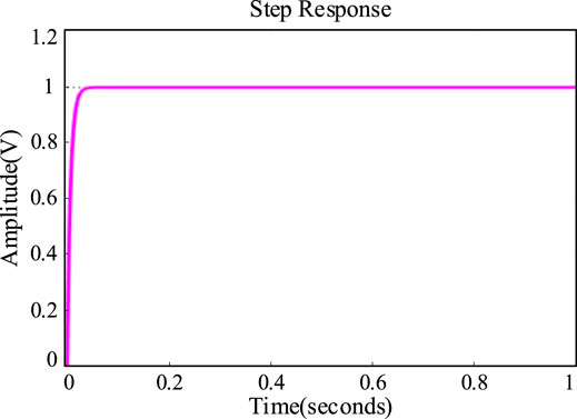
In the design process of the robust controller in this study, by suppressing the external disturbances of the system, the immunity of the system is improved, which enhances the robustness of the system and thus ensures the dynamic characteristics of the system. The stability of the closed-loop system is calculated; after iterative computation for ten times, the optimal ||Tzi||∞ = 0.3184, which ensures the stability of the closed-loop system. As shown in Figure 5, from the designed robust controller step response, the overshoot of the controller is very small and the time to reach the steady state is very short, which further reflects the good dynamic performance of the controller.
Adaptive Virtual Impedance Group
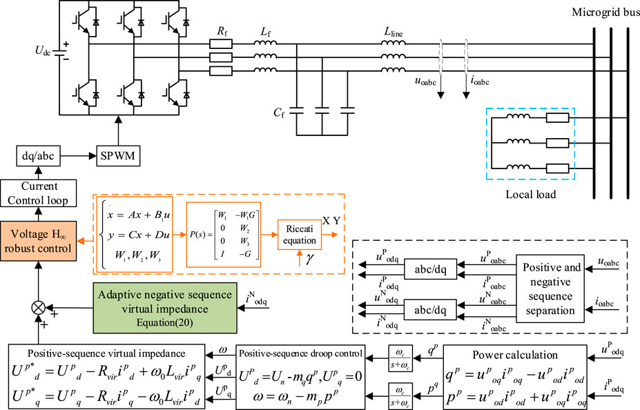
A set of adaptive virtual impedances is designed to further improve the robust stability of the inverter, as shown in Figure 6. It includes the positive sequence virtual impedance, negative sequence virtual impedance, and harmonic virtual impedance.
Adaptive Virtual Impedance Positive Part
The introduction of the adaptive positive sequence virtual impedance can compensate the voltage drop caused by the load switching, which can be realized in the rotating coordinate system as follows:
where Upd* and Upq* are the reference value of d and q axis reference output voltage adjustment, respectively; ω0 is the angular frequency of rotation in the dq coordinate system; and Rvir and Lvir are adaptive virtual resistance and virtual inductance, where Rvir is written as
where R0 is the constant resistance, Δu is the voltage error, and kd1 and kd2 are the proportional adjustment coefficient and integral link coefficient.
Negative Sequence Virtual Impedance
The precise decoupling and power sharing of the inverter may be affected by the unbalanced inverter voltage due to the unbalanced current under the unbalanced load conditions (Jiang et al., 2019). In this case, the proposed adaptive virtual impedance group–negative sequence part can suppress the negative sequence part in the output voltage, to ensure the inverter voltage control performance, the control principle of which is as follows:
where kg is the proportional factor and uNod is the negative sequence part separated from voltage.
The compensation voltage uP can be obtained by the above-mentioned negative impedance and current. Then, it will be used as one of the control signals.
Harmonic Impedance
In microgrid operation, non-linear loads generate a large number of harmonics that affect the power quality of the VSI output. In this case, an adaptive virtual harmonic impedance is proposed to improve the output voltage in the harmonic domain and thus the voltage control performance of the inverter, and its corresponding expression is given as follows:
where uHod is the harmonic part separated from voltage, kH is the virtual harmonic impedance proportional factor, and H is set as the value from 3 to n with general generality. Limited by the switching frequency, the adaptive harmonic impedance method proposed in this study only corrects for harmonics at low frequencies, and n is taken as 9 in the study.
Overall Scheme of the Proposed Robust Control Strategy for VSI
The control system block diagram of the robust control strategy of the VSI is shown in Figure 7.
Simulation Verification
A simulation model of VSI applied in the microgrid is built in MATLAB. The related experiments are designed to verify the effectiveness of the proposed control scheme. The main parameters of the microgrid inverter are given in Table 1.
The comparative experiments are carried out under the traditional control strategy and the proposed control strategy. The load parameters are given in Table 2.
Three-Phase Balanced Loads
Figure 8 shows the voltage waveforms of the inverter with the traditional control strategy. First, when the inverter is running at 0–0.2 s, the VSI voltage waveforms are three-phase sine waves, and the amplitude is rated. When the inverter runs to 0.2 s, the three-phase symmetrical resistance inductive load is incorporated, and the output voltage deviates. When the inverter runs to 0.28 s, a set of three-phase symmetrical resistive inductive loads is added, and the output voltage drops further. As can be seen from the figure, under the traditional control strategy, the inverter output power quality is affected by the load and changes accordingly.
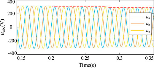
FIGURE 8. Output voltage of the inverter under the traditional control strategy (voltage deviation).
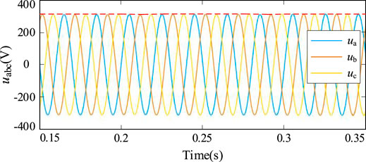
Figure 9 shows the voltage waveforms of the inverter for the control strategy proposed in this study. First, the inverter runs at no load from 0 to 0.2 s, and the inverter output is a three-phase sine wave with the rated amplitude. At 0.2 s of inverter operation, a three-phase symmetrical resistive load is incorporated and the output voltage undergoes a smaller deviation. At 0.28 s, another set of three-phase symmetrical resistive load is incorporated and the output voltage undergoes a smaller voltage deviation, which is subsequently compensated by the controller to the rated value. As can be seen from the figure, the power quality of the output voltage can be guaranteed under the proposed strategy in the study.
Table 3 shows the voltage deviation analysis of VSI under different control strategies. Under the conventional control strategy, the voltage deviation is −4.05% after incorporating the first group of loads and −8.01% after incorporating the second group of loads, and the power quality is further degraded; under the proposed robust control strategy, the voltage deviation is 0.03% after incorporating the first group of loads and 1.09% after incorporating the second group of loads.
Three-Phase Asymmetric Load
Figure 10 shows the voltage waveforms of the inverter with the traditional control strategy. When the three-phase asymmetrical load 1 is added at 0.3 s, the three-phase voltage of the inverter is three-phase asymmetrical, and the degree of three-phase asymmetry is 10.75%. When the three-phase asymmetrical load 2 is added at 0.6 s, the output voltage of the inverter drops further, and the three-phase asymmetry of the inverter is 11.74%. Under the traditional control, the voltage control performance of the inverter changes under different load conditions, which seriously affects the power quality of the inverter output power quality. The three-phase asymmetry is given in Table 3.
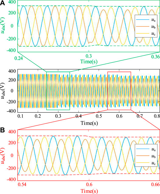
FIGURE 10. Output voltage of the inverter under the traditional control strategy (three-phase unbalance). (A) Three-phase asymmetric load 1. (B) Three-phase asymmetric load 2.
Figure 11 shows the voltage waveforms of the inverter with the proposed control strategy. When the three-phase asymmetrical load 1 is added at 0.3 s, the output voltage of the inverter has a small voltage deviation and then reverts back to the rated value, and the three-phase asymmetry is 1.11%. When the three-phase asymmetrical load 2 is added at 0.6 s, the output voltage of the inverter drops obviously, but it recovers after one cycle, and the three-phase asymmetry degree is 1.51%. The three-phase asymmetry of the output voltage is less than 2% when the asymmetric load is added, which ensures the power quality of the output voltage. The three-phase asymmetry is given in Table 3.
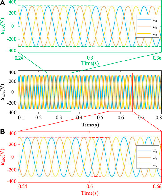
FIGURE 11. Output voltage of the inverter under the proposed control strategy (three-phase unbalance). (A) Three-phase asymmetric load 1. (B) Three-phase asymmetric load 2.
Non-linear Load
The feasibility of the proposed strategy is verified by comparing the power quality of the inverter output voltage when the conventional control strategy is compared with the proposed control strategy with the non-linear load.
Figure 12 shows the inverter voltage (A) and current (B) waveforms under the traditional strategy. At 0.25 s, non-linear loads including the uncontrollable rectifier loads, shunt capacitors, resistors, and inductors are merged into the system. The inverter output voltage deviated significantly, which landed to 280 V, and there was a significant voltage distortion. At this time, the voltage distortion rate was 2.75%. The inverter cannot guarantee the reliability of the voltage. After the non-linear load is incorporated, the inverter output current has a significant distortion, whose rate is 13.85% at this time.
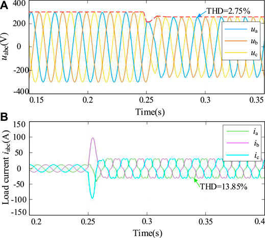
FIGURE 12. Output voltage (A) and current (B) of the inverter under the traditional control strategy (harmonic).
Figure 13 shows the inverter voltage (A) and current (B) waveforms under the control strategy of this study. At 0.25 s, non-linear loads merged into the system, and the inverter output voltage has a significant voltage deviation. The voltage returns to the rated value after one cycle. At this time, the voltage harmonic distortion rate THD is 1.47%, which verified that the proposed strategy can make sure the power quality of the inverter voltage. load Before 0.25 s, the inverter with three-phase resistive inductive load, the load current is three-phase symmetric, and after incorporating the non-linear load, the current distortion occurs obviously, and the harmonic current distortion rate is 10.32% at this time.
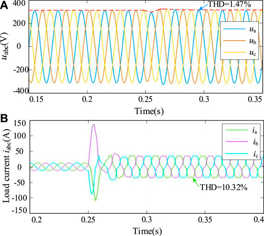
FIGURE 13. Output voltage (A) and current (B) of the inverter under the proposed control strategy (harmonic).
Dynamic Performance Comparison of Control Strategies
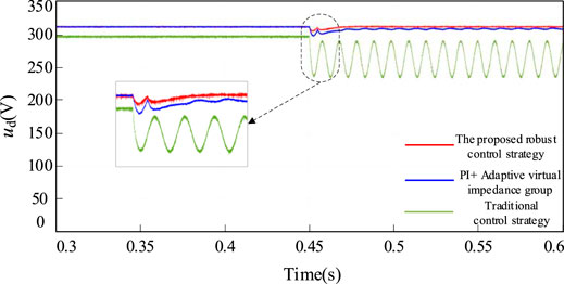
To verify the dynamic performance of the proposed strategy, the comparative experimental results are shown in Figure 14, incorporating a group of unbalanced loads. When the proposed robust control scheme is used, on the one hand, its voltage deviation is smaller than that of a separate PI controller and PI adaptive impedance control; on the other hand, its voltage dynamic recovery performance is also obviously optimal.
Parameter Perturbation Analysis
This experiment is used to verify the robustness and robust control performance of the proposed control strategy in the study while the system parameters are perturbed.
In this case, when the system parameters are perturbed by 30%, the total distortion rate of the three-phase output voltage of VSI is compared, and the results are given in Table 4.
The voltage distortion rate under the traditional control strategy and the control method proposed in this study is shown in Table 4. In the experiment, comparative experiments are carried out without adding system disturbance and adding 30% system disturbance. It can be seen from the results that when the system parameters are severely disturbed, the VSI robust control strategy proposed in this study can improve the robustness of the VSI and ultimately improve the power quality.
Power Sharing Analysis
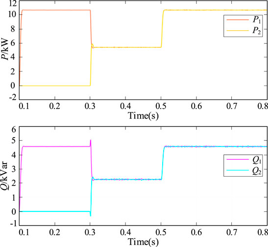
Figure 15 shows the active and reactive power output of the inverter with a three-phase resistive inductive load when the line impedance is the same (line impedance of 1 mH). At 0.3 s, the second inverter is connected to the bus and the power output from the inverter achieves equalization. At 0.5 s, a group of three-phase resistive inductive loads are connected in parallel, and their sizes are shown in Table 3. At this time, the power output of the inverters can still be well equalized.
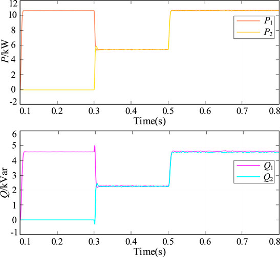
Figure 16 shows the active and reactive power output of the inverter with a three-phase resistive inductive load when the line impedance is different (line 1 impedance drops 10%). At 0.3 s, the second inverter is connected to the bus and the power output from the inverter achieves equalization. At 0.5 s, the three-phase resistive inductive load is pitched, and its magnitude is given in Table 3. At this time, the power output from the inverter can still almost get equalization.
Conclusion
A novel H∞ control scheme for VSI in the microgrid is proposed to improve the robustness of VSI under complicated microgrid conditions. The robust controller is designed to improve the tracking performance, so the main purpose of this article is to ensure the dynamic performance of the VSI. At the same time, the adaptive virtual impedance group is proposed to eliminate the voltage deviation caused by load variation. In the comparative verification, under various microgrid operating conditions, the inverter parameters are perturbed, and the voltage control performance of VSI with the proposed control scheme can be well maintained. In general, under the combination of the H∞ controller and the adaptive virtual impedance group, the dynamic performance and steady-state performance of the inverter output voltage are improved, which further guarantees the good power quality of the inverter output voltage. At the same time, the power output of the inverter can be well equalized. In future studies, the VSI robust control scheme for the microgrid operating under more operating conditions needs to be further optimized, including robust controllers with better robustness and more complete adaptive virtual impedance groups.
Data Availability Statement
The raw data supporting the conclusion of this article will be made available by the authors, further inquiries can be directed to the corresponding author.
Author Contributions
Conceptualization and formal analysis, ZJ and YL; investigation, JZ; validation and writing—original draft preparation, JZ; writing—review and revision, JZ and HS. All authors have read and agreed to the published version of the manuscript.
Funding
This work was supported by the Ningxia Nature Science Foundation (2021AAC03227) and the National Nature Science Foundation (51667002).
Conflict of Interest
The authors declare that the research was conducted in the absence of any commercial or financial relationships that could be construed as a potential conflict of interest.
Publisher’s Note
All claims expressed in this article are solely those of the authors and do not necessarily represent those of their affiliated organizations, or those of the publisher, the editors, and the reviewers. Any product that may be evaluated in this article, or claim that may be made by its manufacturer, is not guaranteed or endorsed by the publisher.
References
Anderson, A. A., and Suryanarayanan, S. (2019). A Comprehensive Review of Energy Management and Planning of Islanded Microgrids: Part 1 - Optimization Formulations. Csee Jpes 6 (2), 329–343. doi:10.17775/CSEEJPES.2019.01080
Beheshtaein, S., Cuzner, R., Savaghebi, M., and Guerrero, J. M. (2019). Review on Microgrids protection. IET Gener. Transm. Distrib. 13 (6), 743–759. doi:10.1049/iet-gtd.2018.5212
Bouzid, A. M., Guerrero, J. M., Cheriti, A., Bouhamida, M., Sicard, P., and Benghanem, M. (2015). A Survey on Control of Electric Power Distributed Generation Systems for Microgrid Applications. Renew. Sustain. Energ. Rev. 44, 751–766. doi:10.1016/j.rser.2015.01.016
Bouzid, A. M., Sicard, P., Cheriti, A., Bouhamida, M., and Benghanem, M. (2015). “Structured H∞ Design Method of PI Controller for Grid Feeding Connected Voltage Source Inverter,” in 3rd International Conference on Control Engineering & Information Technology CEIT, Tlemcen, Algeria, 1–6. doi:10.1109/CEIT.2015.7233086
Bouzid, A. M., Sicard, P., Paquin, J.-N., and Yamane, A. (2016). “A Robust Control Strategy for Parallel-Connected Distributed Generation Using Real-Time Simulation,” in IEEE 7th International Symposium on Power Electronics for Distributed Generation Systems (PEDG), Vancouver, BC, Canada, 1–8. doi:10.1109/PEDG.2016.7527055
Chen, J., Yue, D., Dou, C., Li, Y., Hancke, G. P., Weng, S., et al. (2021). Distributed Control of Multi-Functional Grid-Tied Inverters for Power Quality Improvement. IEEE Trans. Circuits Syst. 68 (2), 918–928. doi:10.1109/TCSI.2020.3040253
Das, S. R., K Ray, P., and K Sahoo, A. (2020). Improvement of Power Quality in a Three-phase System Using an Adaline-Based Multilevel Inverter. Front. Energ. Res. 8. doi:10.3389/fenrg.2020.00023
Dehkordi, N. M., and Nekoukar, V. (2020). Robust Reliable Fault Tolerant Control of Islanded Microgrids Using Augmented Backstepping Control. IET Gener., Transm. Distrib. 14 (3), 432–440. doi:10.1049/iet-gtd.2019.1264
Dezhou, L., Hang, Q., Chong, L., Zhe, J., and Siyang, F. (2019). A Converter Control Strategy Based on Droop Control in Distributed Generation Systems. in 2019 IEEE Innovative Smart Grid Technologies - Asia (ISGT Asia), Chengdu, China, 1762–1765. doi:10.1109/ISGT-Asia.2019.8880922
Dheer, D. K., Gupta, Y., and Doolla, S. (2020). A Self-Adjusting Droop Control Strategy to Improve Reactive Power Sharing in Islanded Microgrid. IEEE Trans. Sustain. Energ. 11 (3), 1624–1635. doi:10.1109/TSTE.2019.2933144
Geng, Y., Hou, M., Zhu, G., Liu, Y., Yu, H., and Hu, Y. (2020). Resistive Droop Control Strategy of Active Power Distribution Form Microgrid Based on Virtual Impedance. Electric Power Automation Equipment 40 (10), 132–138. doi:10.16081/j.epae.202008021
Jiang, Z., Shi, H., Zhu, L., and Gao, T. (2019). “A Negative Sequence Voltage Control Strategy Based on Adaptive Virtual Impedance Implementation for Microgrid Inverter under Three-phase Unbalanced Load,” in PEDG 2019-2019 IEEE 10th International Symposium on Power Electronics for Distributed Generation Systems, 978–980. doi:10.1109/PEDG.2019.8807755
Lai, N.-B., and Kim, K.-H. (2018). Robust Control Scheme for Three-phase Grid-Connected Inverters with LCL-Filter under Unbalanced and Distorted Grid Conditions. IEEE Trans. Energ. Convers. 33 (2), 506–515. doi:10.1109/TEC.2017.2757042
Li, P., Yu, X., and Zhao, B. (2016). H∞ Robust Voltage Control of AC-DC Interface Based on Mixed Sensitivity in AC-DC Hybrid Micro-grid. Proc. Chin. Soc. Electr. Eng. 36 (1), 68–75. doi:10.13334/j.0258-8013.pcsee.2016.01.007
Liu, X., Lin, C., Chen, T., Li, J., and Chen, Z. (2017). Reactive Power-Voltage Control Strategy of AC Microgrid Based on Adaptive Virtual Impedance. Automation Electric Power Syst. 41 (5), 16–21. doi:10.7500/AEPS20160428017
Liu, Z., Liu, J., Hou, X., Dou, Q., Xue, D., and Liu, T. (2015). Output Impedance Modeling and Stability Prediction of Three-phase Paralleled Inverters with Master-Slave Sharing Scheme Based on Terminal Characteristics of Individual Inverters. IEEE Trans. Power Electron. 31 (7), 1. doi:10.1109/TPEL.2015.2483741
Mazidi, M., Rezaei, N., Ardakani, F. J., Mohiti, M., and Guerrero, J. M. (2020). A Hierarchical Energy Management System for Islanded Multi-Microgrid Clusters Considering Frequency Security Constraints. Int. J. Electr. Power Energ. Syst. 121, 106134. doi:10.1016/j.ijepes.2020.106134
Nejabatkhah., F., Li, Y. W., and Sun, K. (2018). Parallel Three-phase Interfacing Converters Operation under Unbalanced Voltage in Hybrid AC/DC Microgrid. IEEE Trans. Smart Grid 9 (2), 1310–1322. doi:10.1109/TSG.2016.2585522
Pathan, E., Abu Bakar, A., Zulkifi, S. A., Khan, M. H., Arshad, H., and Asad, M. (2020). A Robust Frequency Controller Based on Linear Matrix Inequality for a Parallel Islanded Microgrid. Eng. Technol. Appl. Sci. Res. 10 (5), 6264–6269. doi:10.48084/etasr.3769
Pradhan, S. S., Pradhan, R., and Subudhi, B. (2019). “Design and Analysis of an $H_{\infty}$ Controller for a Single Phase Grid Connected Photovoltaic System with Parametric Uncertainties,” in IEEE Second International Conference on Advanced Computational and Communication Paradigms (ICACCP), 1–6. doi:10.1109/ICACCP.2019.8882898
Rasekh, N., and Hosseinpour, M. (2020). LCL Filter Design and Robust Converter Side Current Feedback Control for Grid-Connected Proton Exchange Membrane Fuel Cell System. Int. J. Hydrogen Energ. 45 (23), 13055–13067. doi:10.1016/j.ijhydene.2020.02.227
Rathore, B., Chakrabarti, S., and Srivastava, L. (2021). A Self-Regulated Virtual Impedance Control of VSG in a Microgrid. Electric Power Syst. Res. 197, 107289. doi:10.1016/j.epsr.2021.107289
Sadabadi, M. S., Shafiee, Q., and Karimi, A. (2017). Plug-and-Play Voltage Stabilization in Inverter-Interfaced Microgrids via a Robust Control Strategy. IEEE Trans. Contr. Syst. Technol. 25 (3), 781–791. doi:10.1109/TCST.2016.2583378
Sarmiento, J. E., Carreno, E. M., and Zambroni de Souza, A. C. (2018). Modeling Inverters with Volt-Var Functions in Grid-Connected Mode and Droop Control Method in Islanded Mode. Electric Power Syst. Res. 155, 265–273. doi:10.1016/j.epsr.2017.10.020
Sedhom, B. E., El-Saadawi, M. M., Elhosseini, M. A., Saeed, M. A., and Abd-Raboh, E. E. (2020). A harmony Search-Based H-Infinity Control Method for Islanded Microgrid. ISA Trans. 99, 252–269. doi:10.1016/j.isatra.2019.10.014
Shi, H., Zhuo, F., Yi, H., and Geng, Z. (2016). Control Strategy for Microgrid under Three-phase Unbalance Condition. J. Mod. Power Syst. Clean. Energ. 4 (1), 94–102. doi:10.1007/s40565-015-0182-3
Shokri, A., Shareef, H., Mohamed, A., Farhoodnea, M., and Zayandehroodi, H. (2015). A Novel Controller for a Voltage Controlled Voltage Source Inverter to Mitigation Voltage Fluctuations Measured at the point of Common Coupling. Measurement 59, 216–226. doi:10.1016/j.measurement.2014.09.042
Sun, X., Hao, Y., Wang, B., Sheng, H., and Guo, X. (2016). State-of-charge Balancing of Distributed Energy Storage Units and Voltage Restoration in Microgrid. Proc. Chin. Soc. Electr. Eng. 36 (15), 4047–4054. doi:10.13334/j.0258-8013.pcsee.150963
Taher, S. A., and Zolfaghari, M. (2014). Designing Robust Controller to Improve Current-Sharing for Parallel-Connected Inverter-Based DGs Considering Line Impedance Impact in Microgrid Networks. Int. J. Electr. Power Energ. Syst. 63, 625–644. doi:10.1016/j.ijepes.2014.06.035
Tian, M., Chen, M., Zhao, Y., and Wang, J. (2016). A Novel Method of Reactive Power Compensation Network Design for Three Phase Unbalanced Load System. Power Syst. Tech. 40 (3), 897–903. doi:10.13335/j.1000-3673.pst.2016.03.034
Vahab, N. (2020). Robust Reliable Fault Tolerant Control of Islanded Microgrids Using Augmented Backstepping Control. IET Generation, Transm. Distribution 14 (3), 432–440. doi:10.1049/iet-gtd.2019.1264
Wang, T., Nian, H., Zhu, Z. Q., Ding, L., and Zhou, B. (2018). Flexible Compensation Strategy for Voltage Source Converter under Unbalanced and Harmonic Condition Based on a Hybrid Virtual Impedance Method. IEEE Trans. Power Electron. 33 (9), 7656–7673. doi:10.1109/tpel.2017.2768381
Wang, Y., Wang, X., Blaabjerg, F., and Chen, Z. (2017). Harmonic Instability Assessment Using State-Space Modeling and Participation Analysis in Inverter-Fed Power Systems. IEEE Trans. Ind. Electron. 64 (1), 806–816. doi:10.1109/TIE.2016.2588458
Wang, Z., Zhuo, F., Yi, H., Wu, J., Wang, F., and Zeng, Z. (2019). Analysis of Dynamic Frequency Performance Among Voltage-Controlled Inverters Considering Virtual Inertia Interaction in Microgrid. IEEE Trans. Ind. Applicat. 55 (4), 4135–4144. doi:10.1109/TIA.2019.2910784
Xin, H., Zhang, L., Wang, Z., Gan, D., and Wong, K. P. (2015). Control of Island AC Microgrids Using a Fully Distributed Approach. IEEE Trans. Smart Grid 6 (2), 943–945. doi:10.1109/TSG.2014.2378694
Xiongfei Wang, X., Blaabjerg, F., and Zhe Chen, Z. (2014). Autonomous Control of Inverter-Interfaced Distributed Generation Units for Harmonic Current Filtering and Resonance Damping in an Islanded Microgrid. IEEE Trans. Ind. Applicat. 50 (1), 452–461. doi:10.1109/TIA.2013.2268734
Xu, Y., Sun, H., Gu, W., Xu, Y., and Li, Z. (2019). Optimal Distributed Control for Secondary Frequency and Voltage Regulation in an Islanded Microgrid. IEEE Trans. Ind. Inf. 15 (1), 225–235. doi:10.1109/TII.2018.2795584
Yang, X., Su, J., Lv, Z., Liu, H., and Li, R. (2014). Overview on Micro-grid Technology. Proceeding Chin. Soc. Electr. Eng. 34 (1), 57–70. doi:10.13334/j.0258-8013
Yi, H., Zhuo, F., Zhang, Y., Li, Y., Zhan, W., Chen, W., et al. (2014). A Source-Current-Detected Shunt Active Power Filter Control Scheme Based on Vector Resonant Controller. IEEE Trans. Ind. Applicat. 50 (3), 1953–1965. doi:10.1109/TIA.2013.2289956
Keywords: H∞ robust control, mixed sensitivity, parameter perturbation, voltage stability, adaptive virtual impedance group
Citation: Shi H, zhang J, Zhou J, Li Y and Jiang Z (2021) A Novel H∞ Robust Control Strategy for Voltage Source Inverter in Microgrid. Front. Energy Res. 9:731432. doi: 10.3389/fenrg.2021.731432
Received: 27 June 2021; Accepted: 06 September 2021;
Published: 14 October 2021.
Edited by:
Liansong Xiong, Nanjing Institute of Technology (NJIT), ChinaReviewed by:
Liu Baoquan, Shaanxi University of Science and Technology, ChinaFeng Wang, Xi’an University, China
Shamsul Zulkifli, Universiti Tun Hussein Onn Malaysia, Malaysia
Copyright © 2021 Shi, zhang, Zhou, Li and Jiang. This is an open-access article distributed under the terms of the Creative Commons Attribution License (CC BY). The use, distribution or reproduction in other forums is permitted, provided the original author(s) and the copyright owner(s) are credited and that the original publication in this journal is cited, in accordance with accepted academic practice. No use, distribution or reproduction is permitted which does not comply with these terms.
*Correspondence: Jie zhang, 13519288232@163.com
 Hongtao Shi