- 1Key Laboratory of Modern Power System Simulation and Control and Renewable Energy Technology Ministry of Education (Northeast Electric Power University), Jilin, China
- 2Key Laboratory of Control of Power Transmission and Conversion (Shanghai Jiao Tong University), Ministry of Education, Shanghai, China
- 3Department of Electrical Engineering, Nantong University, Nantong, China
The kinetic energy stored in the doubly-fed induction generators (DFIG)-based wind farm can be utilized to sustain the dynamic system frequency. However, difficulties arise in determining the control gain to effectively improve the frequency nadir and smoothly return to the maximum power point tracking (MPPT) operation. This paper addresses a two-phase short-term frequency response (STFR) scheme to boost the frequency nadir and minimize the second drop in the system frequency based on a piecewise control gain. To achieve the first goal, a constant control coefficient, which is determined according to the initial operating conditions of the DFIG-based wind farm, is employed until the frequency nadir produces. To achieve the second goal, the control coefficient, which changes with time, facilitates to smoothly return to the MPPT operation. The effectiveness of the proposed two-phase STFR scheme is verified under various wind power penetration levels, wind speeds, and disturbances. The results reveal that the frequency nadir is improved, and simultaneously, it smoothly returns to the MPPT operation and minimizes the second drop in the system frequency.
Introduction
During the past few years, the power grid with renewable power generations has been experiencing a reduction of the primary frequency response capability and system inertia response capability (Xiong et al., 2020)− (Xiong et al., 2021a; Xiong et al., 2021b). The reason is that conventional synchronous generators (SGs) are replaced by electronic converter-based renewable power generations, which cannot provide the system inertia response and primary response. This tendency continues to increase in renewable power generation-dominated power systems (Yang et al., 2018). Hence, renewable power generations are required to provide frequency response functions to boost the system frequency nadir (National Grid UK, 2010; EirGrid Grid Code Version 6.0, 2015).
Electronic converter interfaced variable-speed wind turbine generators (VSWTGs), e.g., doubly-fed induction generators (DFIGs), which are the most promising replacement for SGs, are able to provide frequency response functions for sustaining the dynamic system frequency by designing the control strategies (Dreidy and Mokhlis, 2017)− (Wu et al., 2019).
The frequency response functions include long-term frequency response (utilizing reserve power of the VSWTGs implemented by over-speed control, pitch angle control, or both of them) (Ye et al., 2019; Cai et al., 2020), and short-term frequency response (utilizing kinetic energy of the VSWTGs).
When performing long-term frequency response, the VSWTGs are forced to operate in deloading mode. Although it ensures a secure reserve power for supporting the system frequency, significant annual wind energy loss is inevitable. Furthermore, the slow response of the pitch angle control and increasing mechanical stress caused by frequent activations of pitch angle are not beneficial to participate in frequency support (Li et al., 2017; Yang et al., 2021a).
Short-term frequency response (STFR) sustains the dynamic system frequency based on two additional control loops: df/dt control loop and droop control loop. Vyver (2016) shows that even though the df/dt loop can emulate the inertia response of SG to boost the system frequency nadir, it creates a power system instability due to the noise in the system frequency. The droop control can emulate governor response of SGs and is taken into account as an alternative inertial control of VSWTGs (Li et al., 2017). The contribution of droop control is analyzed and with various constant control gains, it illustrates that the droop control with fixed gain is not suitable for various wind speed conditions and may cause stalling of the DFIG (Margaris et al., 2012; Hu and Wu, 2019). The variable control gain is, thus, suggested for boosting the frequency stability while preventing stalling of DFIGs (Lee et al., 2016; Hu and Wu, 2019). However, the control gain of Ref. (Lee et al., 2016) is a quadratic function of the rotor speed, and it is not feasible to be implemented in the DFIG. To avoid this, the linear control gain is suggested to provide approximated performance of the quadratic droop control gain (Hu and Wu, 2019).
After the frequency support phase, returning to the maximum power point tracking (MPPT) operation and rotor speed recovery may potentially create a second drop in the frequency (Garmroodi et al., 2018). To mitigate it, the authors reset the setting of the governor response to provide more output power from SGs (Xu et al., 2018). Another strategy employs energy storage systems to prevent the second drop in the frequency when returning to the MPPT operation (Wu et al., 2017). However, both strategies require additional investments for additional reserve power of SGs and energy storage systems (Bao et al., 2020). Furthermore, (Zhong et al., 2021; Kheshti et al., 2019) mention that the strategy for regaining the rotor speed and mitigating the second frequency drop should be considered during the MPPT operation recovery phase. However, it should be pointed out that the strategy to return to the MPPT operation or quit the frequency support phase has not been paid enough attention (Peng et al., 2020).
This paper presents a two-phase STFR scheme of a DFIG-based wind farm that effectively sustains the system frequency and smoothly returns to the MPPT operation while minimizing the second drop in the system frequency. For these objectives, this paper determines the control gain as a piecewise function, which remains fixed prior to the frequency nadir to boost the frequency nadir; the control gain then linearly decreases with time to smoothly regain the rotor speed after the frequency nadir. The performance of the two-phase STFR is investigated under three scenarios with different wind speed conditions, wind power penetration levels, and sizes of disturbance.
Model of the Doubly-Fed Induction Generator
The extracted mechanical power (Pm) by the wind turbine from wind can be defined as a nonlinear function of air density (ρ), power coefficient (cp), wind speed (vw), and rotor radius (R), as in:
where β and λ, respectively, represent pitch angle and tip-speed ratio.
As in Boukhezzar and Siguerdidjane (2011), cp(λ, β) used in this study is a function related to λ and β, which can be represented as:
where
To illustrate the dynamics between the induction machine and wind turbine, one two-mass model is implemented, as shown in Eqs 5−7. Among them, Ht, ωt, Tt, and Dt are, respectively, the inertia time constant, angular speed, torque, and damping constant of the turbine of the DFIG; Hg, ωr, Tg, and Dg are, respectively, the inertia time constant, angular speed, torque, and damping constant of the induction generator; and Ds, Ks, ω, and θs are, respectively, the damping constant, shaft stiffness, base value of angular speed, and torsional twist (Ajjarapu et al., 2010).
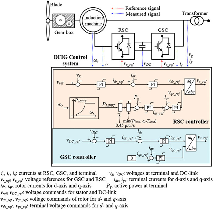
As shown in Figure 1, the DFIG control system receives the measurements and determines the commands for a rotor-side converter (RSC) and grid-side converter (GSC) controllers. The top loop of the RSC controller focuses on maintaining the voltage of stator. Its bottom loop focuses on controlling the output fed to the power grid (see Figure 1). The top loop of the GSC controller controls the DC-link voltage (Figure 1). Its bottom loop regulates the requested reactive power (Fernandez et al., 2008).
Fundamental Features of Short-Term Frequency Response Strategies of a Doubly Fed Induction Generator
When performing inertia control of the DFIG, the additional power, ∆Pin, can be expressed as:
where fsys means the system frequency. HDFIG is the inertia constant of the DFIG and includes the inertia constants of induction generator and turbine.
Integrating Eqs 8, 9 can be derived as:
where fsys(t) and fsys(t+∆t), respectively, are the system frequencies at t and t + ∆t. ∆t is the time interval.
Rearranging Eq. 9:
In Eq. 10, it is shown that with the larger additional injected power, the system frequency deviation becomes less.
As in Lee et al. (2016), the available kinetic energy from DFIGs is represented as:
where ω0 and ωmin, respectively, are the rotor speed before disturbance and minimum rotor speed limit.
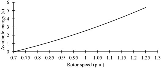
In addition, Eq. 11 can be utilized to calculate the released energy by substituting the minimum rotor speed during STFR for ωmin. STFR of DFIGs mainly relies on ω0, as shown in Figure 2. Furthermore, if the rotor speed decreases to ωmin during droop control, stalling of the wind turbine is caused by excessive release of the kinetic energy.
Conventional Short-Term Frequency Response of a Doubly Fed Induction Generator
The characteristics of the STFR with droop control are similar to that of the primary response of SGs. Unlike in the governor response, the droop control from DFIGs releases the kinetic energy from the rotating masses without reserve power.
When performing droop control, the power reference is expressed as follows:
where ΔPdroop indicates the output of droop control loop, Kdr represents the control gain of the droop control, and fnom denotes the nominal system frequency.
According to Eq. 13, the short power injected to the power grid from the droop control loop strongly depends on Kdr, which becomes large so as to improve the frequency nadir.
As illustrated in Figure 2, the retained kinetic energy of a DFIG for various wind conditions is different, therefore, increasing the difficulties of setting the control gain for various rotor speeds. To mitigate this problem, Ref. (Hu and Wu, 2019) addresses a linear variable droop gain, which is expressed as:
where C indicates a constant and determines the contribution of the STFR of the DFIG.
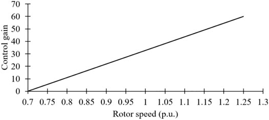
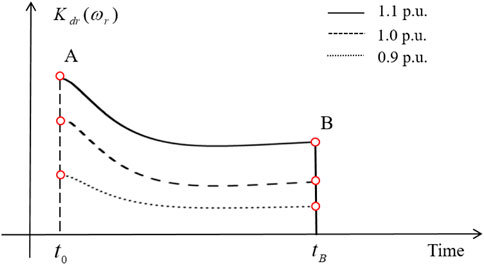
As in Eq. 14 and Figure 3, there are two key features of the linear variable control gain. The first is that the linear variable droop gain is a monotonously linear function related to the rotor speed. This implies that the STFR becomes better with the increasing ωr. The second is that Kdr(ωr) is zero when ωr = ωmin, so that it effectively avoids the stalling of DFIGs. Nevertheless, in the initial stage of a disturbance, Kdr(ωr) becomes small with the decreasing ωr until the system frequency passes into the steady state (Figures 4A,B) so that the injected power from the DFIG decreases; therefore, the DFIG could not effectively improve the frequency nadir.
Another point to be considered is that after the frequency support phase, the DFIG should return back to MPPT operation in order to regain the kinetic energy. For the conventional STFR scheme, to quit the frequency support phase and return to the MPPT operation, ΔPdroop in Eq. 12 and Kdr(ωr) in Eq. 13 instantly decrease to zero. This indicates that the power reference of the DFIG stepwise switches back to the MPPT operation. According to the swing equation, if ΔPdroop decreases to zero, the right hand side of Eq. 15 becomes negative; as a result, the system frequency decreases and produces a second frequency drop. The decreased shape of ΔPdroop judges the size of the second frequency deviation. Furthermore, a large drift in the rotor speed from its initial value consequently causes a significantly deep second frequency drop (Garmroodi et al., 2018). In some cases, the second drop in the system frequency may be lower than the first frequency nadir. This conclusion can be confirmed in the simulation results of this study.
where Jsys is the moment inertia of the power system. Pload and PSG, respectively, mean the system load and total output power SGs.
Two-phase Short-Term Frequency Response of a Doubly Fed Induction Generator
This paper aims to 1) improve the frequency nadir during the frequency support phase, and 2) minimize the size of a second drop in the system frequency during the MPPT operation recovery phase. For these objectives, this paper determines the control gain as a piecewise function, which remains fixed prior to the frequency nadir and linearly decreases with time after the frequency nadir.
Frequency Support Phase of a Doubly Fed Induction Generator
Compared with the conventional STFR, to inject more output before the frequency nadir appears, the control gain in this study is defined as a constant prior to the frequency nadir, as in:
where C is a constant the same as in Eq. 14; t0 and tFN, respectively, represent the moment when starting up STFR and moment of the frequency nadir occurrence after a disturbance.
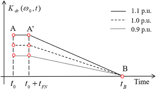
As illustrated in Figure 5 and Eq. 16, the initial value of the proposed control gain is proportional to the initial conditions of DFIGs and maintained fixed until the frequency nadir appearance (from A to A′ in Figure 5). For the conventional STFR, at the instant of detecting disturbance, the control gain is the same as in the two-phase STFR; after that, the control gain decreases with reducing rotor speed. Therefore, the proposed two-phase STFR is able to inject more power from DFIGs to support the system frequency compared with the conventional STFR.
Maximum Power Point Tracking Operation Recovery Phase of a Doubly Fed Induction Generator
During the MPPT operation recovery phase, to compromise the second drop in the system frequency and the time of the rotor speed recovery, the ΔPdroop in Eq. 12 should gradually decrease to zero instead of stepwise decreasing to zero. To this end, a weighting factor of time shown in Eq. 17 is considered based on Eq. 16 to determine the control gain during the MPPT operation recovery. Thus, the control gain can be represented as in Eq. 18.
After the frequency nadir appears, the control gain gradually decreases to zero so that the output power of the DFIG smoothly decreases to the MPPT curve (from A′ to B in Figure 5). This is the reason why the proposed two-phase STFR can minimize the secondary frequency drop while smoothly returning to the MPPT operation. Furthermore, the proposed two-phase STFR initiates the MPPT operation recovery significantly earlier compared with the conventional strategy so that it can ensure a similar duration of the restoration of ωr while minimizing the second drop in the system frequency.
In this paper, the frequency nadir detector is used to switch the control gain from Eq. 14–16 once the measured df/dt meets the following condition:
For the robust df/dt measurement, two low-pass filters are used in this study. When calculating the system frequency, a second-order low-pass filter is used for a phase-locked loop (PLL) in a VSWTG controller and its cutoff frequency is 1 Hz. In addition, when calculating df/dt, a first-order low-pass filter is used. If the calculated meets Eq. 19, the waiting counter increases by one; otherwise, it decreases by one. Once the counter equals five, the frequency nadir is detected. This way of detecting the frequency nadir may detect the frequency nadir earlier or later than the actual value. Therefore, special attention should be paid on selecting countermeasures against noise components to avoid the adverse impact on the performance of the proposed scheme caused by earlier or later detection of the frequency nadir.
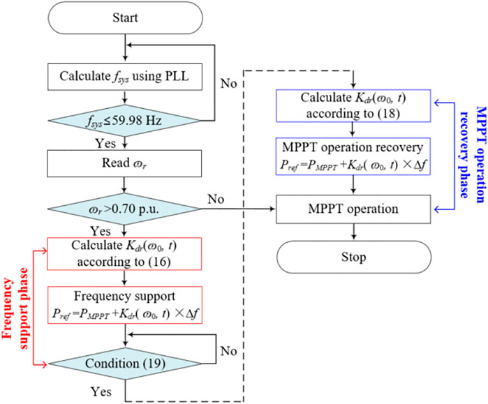
Figure 6 shows the flowchart of the proposed two-phase STFR strategy, which includes four parts: disturbance detecting part, frequency support part, frequency nadir detecting part, and MPPT operation recovery part.
Limitations of the Active Power Reference of a Doubly Fed Induction Generator
To obtain the realistic results while protecting VSWTGs, the power reference is limited by the limiter of maximum power (Plimit) and the limiter of the rate of change in power (ωrTlimit). The former limiter is set to 10% or 20% more than that of the nominal power of a VSWTG (Margaris et al., 2012; Bao et al., 2020). In addition, the setting of the latter limiter is 0.45 p.u./s (Hu and Wu, 2019; Zhong et al., 2021). The upper limit is the minimum value between Plimit and ωrTlimit.
Model System
Figure 7 illustrates the model system to indicate the efficacy of the two-stage STFR scheme in EMTP-RV. It comprises two DFIG-based wind farms, static load, six SGs, and motor load. Total load consumption is 529 MW.
Synchronous Generators
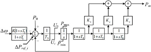
The model system includes two 200-MVA SGs, two 150-MVA SGs, and two 100-MVA SGs, as shown in Figure 7. The inertia constants of 100-MVA SG, 150-MVA SG, and 200-MVA SG are, respectively, set to 4, 4.3, and 5 s (Hu and Wu, 2019). In addition, six SGs are assumed as steam turbine generators with the tandem-compound, single-reheat IEEEG1 governor model (Byerly et al., 1973). The configuration of the governor model and its coefficients are, respectively, illustrated in Figure 8 and Table 1. IEEE X1 is used for voltage control.
Doubly Fed Induction Generator
Two aggregated DFIG-based wind farms are modeled in this paper. To deliver the power to the main grid, two 72-MVA transformers and one 22 km 154-kV submarine cable are used (see Figure 7).
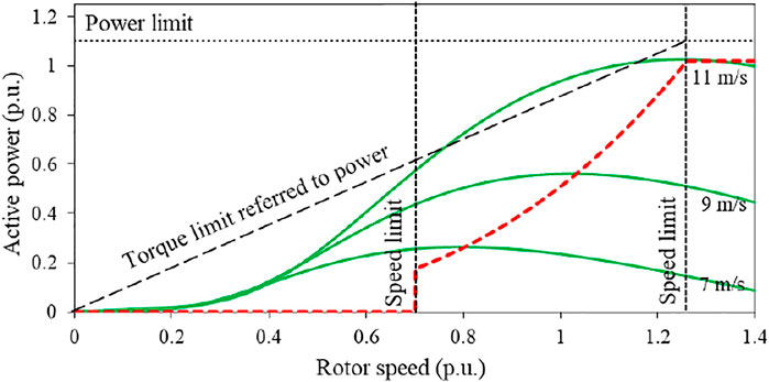
As illustrated in Figure 9, the defined stable ωr operating range of the DFIG ranges from 0.7 to 1.25 p.u. (Yang et al., 2021b); therefore, once ωr reaches 0.7 p.u., the STFR schemes are disabled to prevent the DFIG from stalling. The power limit of the DFIG is 1.1 p.u.
Case Studies
The performance of the two-phase STFR strategy is investigated by comparing it with the conventional STFR strategy and MPPT operation under three scenarios with different wind conditions, wind penetration levels, and sizes of disturbance. The input wind speeds of first DFIG-based wind farm and second DFIG-based wind farm, which are denoted as DFIG1 and DFIG2, are, respectively, 7.5 and 9.5 m/s. At 40 s, SG4 supplying 90 MW for Case 1 and Case 2, and 120 MW for Case 3, is tripped as frequency disturbances. For the proposed and conventional STFR scheme, C in Eqs 14, 16, 18 is set to 60. Once the system frequency passes into the steady state, the conventional STFR scheme decreases the output power for returning to the MPPT operation. For the proposed two-phase frequency support scheme, MPPT operation recovery starts up when Eq. 19 is satisfied. Δt in Eq. 18 is set to 20 s so as to ensure a similar duration of the rotor speed recovery while minimizing the second drop in the system frequency.
Case 1: Wind Penetration of 19% and 90-MW Generator Trip
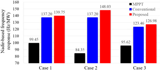
Figure 10 illustrates the results for Case 1. The frequency nadir for the proposed two-phase STFR, conventional STFR, and MPPT operation are 59.356, 59.344, and 59.095 Hz, respectively. The two-phase STFR has the highest frequency nadir because of the most power injection, as shown in Figure 10B. For the conventional STFR, the severe second drop in the system frequency occurs at 64 s because the MPPT operation recovery begins and the output power instantly decreases to the MPPT curve, as illustrated in Figures 10A,B. However, in the proposed two-phase STFR, even if it has a similar rotor speed recovery, no second drop in the system frequency is produced since the output power smoothly decreases to the MPPT operation curve. The nadir-based frequency response of the proposed two-phase STFR is better compared with the conventional STFR because of the less system frequency deviation.
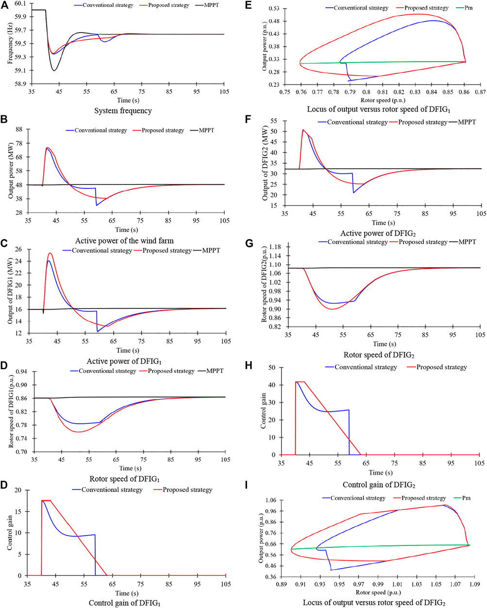
FIGURE 10. Results for case 1. (A) System frequency. (B) Active power of the wind farm. (C) Active power of DFIG1. (D) Rotor speed of DFIG1, Control gain of DFIG1. (E) Locus of output versus rotor speed of DFIG1. (F) Active power of DFIG2. (G) Rotor speed of DFIG2. (H) Control gain of DFIG2. (I) Locus of output versus rotor speed of DFIG2
As illustrated in Figures 10C,F, in the conventional STFR, the output peak value for the DFIG1 is 24.4 MW, which is less than that of the proposed two-phase STFR by 0.7 MW due to the large control gain of the two-phase STFR. The peak value of the output power for the DFIG2 is the same as in the proposed two-phase STFR since the output power is limited by the torque limit.
During the frequency support phase, the released kinetic energies in the conventional STFR for the DFIG1 and DFIG2 are 0.633 and 1.577 s, respectively; the released kinetic energies in the proposed two-phase STFR for the DFIG1 and DFIG2 are 0.818 and 1.814 s, respectively, which are more than those in the conventional STFR, as illustrated in Figures 10D,G.
Figures 10E,I illustrate the locus of output power versus rotor speed for DFIG1 and DFIG2. It can be observed that the output power of the proposed two-phase STFR gradually decreases to the MPPT operation curve, whereas the output power of the conventional STFR instantly decreases to the MPPT operation curve; as a result, the proposed STFR can minimize the second dip in the frequency, but the conventional STFR results in a severe second drop in the system frequency.
Case 2: Wind Penetration of 28% and 90-MW Generator Trip
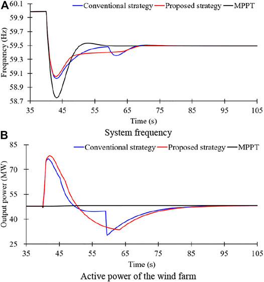
Figure 11 illustrates the results for Case 2 with a higher wind power penetration level of 28% compared with Case 1. To realize this, SG6 is out of service, while the capacities of both the DFIG1 and DFIG2 increase from 50 to 75 MW, respectively. Thus, the system inertia constant becomes less, and the primary frequency response capability becomes worse.
The frequency nadir for the MPPT operation is 58.933 Hz, which is less than that of low wind power penetration (Case 1); this is because of the reduced inertia constant and primary frequency response capability. In the conventional STFR, the first frequency nadir is 59.357 Hz caused by the disturbance. However, during the MPPT operation recovery phase, a severe second drop in the system frequency is caused, which leads the system frequency nadir decrease to 59.344 Hz. In the proposed two-phase STFR, the frequency nadir is 59.392 Hz, which is much more compared with that of the conventional STFR, as in Case 1. Furthermore, no second frequency drop is created. The reasons are that more active power is injected to the power grid, and the output power smoothly decreases to the MPPT curve. Moreover, as in Case 1, due to the higher-frequency nadir, the nadir-based frequency response for the two-phase STFR is more than the other schemes.
Case 3: Wind Penetration of 19% and 120-MW Generator Trip
Figure 12 shows the results for Case 3 with a severe disturbance compared with Case 1. Thus, the system frequency deviation becomes large, and more additional power should be compensated for the larger disturbance.
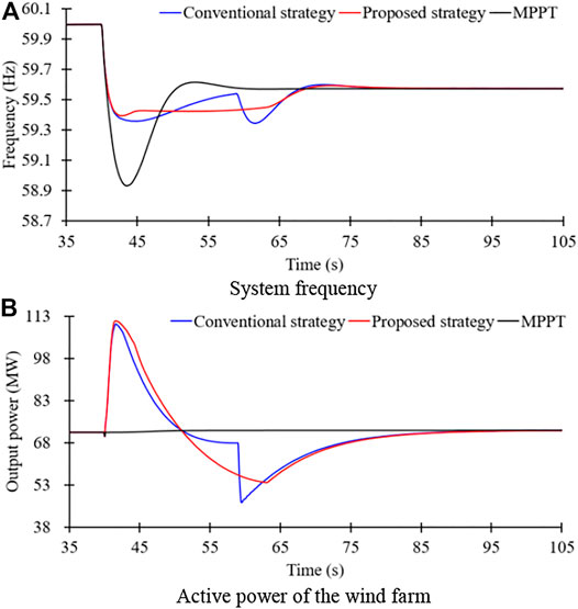
The frequency nadir for the MPPT operation is 58.745 Hz, which is less than that of small disturbance; this is because of the large power deficiency. In the conventional STFR, the frequency nadir is 59.028 Hz, which is less than that of the proposed two-phase STFR by 0.027 Hz. Furthermore, as in previous two cases, the nadir-based frequency response in the proposed two-phase STFR is large compared with that of the conventional STFR. A significant second frequency drop produces around 64 s; however, the proposed two-phase STFR can minimize the second frequency drop while ensuring the similar rotor speed recovery to the conventional STFR, as in Case 1 and Case 2.
Figures 13, 14 show the comparison results of the proposed two-phase STFR to the conventional STFR for the three cases. Since the control gain is fixed prior to the frequency nadir, the frequency nadir and nadir-based frequency response of the two-phase STFR scheme are higher than those of the conventional scheme under various wind power penetration levels and sizes of disturbance. Furthermore, since the control gain linearly decreases with time, the two-phase STFR scheme minimizes the second drop in the system frequency and smoothly recovers the DFIG to the MPPT operation.
Conclusion
This paper proposes a two-phase STFR scheme based on a piecewise droop control gain for the DFIG-based wind farm. During the frequency support phase (prior to the frequency nadir), the droop control gain remains fixed to improve the frequency nadir determined by the initial DFIG operating conditions. During the MPPT operation recovery phase, the droop control gain linearly decreases with time to minimize the second drop in the system frequency and smoothly return to the MPPT operation.
Although the concept is applicable to VSWTGs (DFIG and full-scale VSWTGs), in this paper, we only use the DFIG to illustrate the concept. Results clearly indicate that the two-phase STFR scheme is beneficial in improving the frequency nadir and minimizing the second drop in the system frequency under three scenarios with different wind conditions, wind power penetration levels, and sizes of disturbance. Thus, the proposed two-phase STFR provides benefits to the system frequency stability.
A distributed model of the DFIG-based wind farm would have been more realistic compared with using an aggregated model. In the future, the coordinated control strategy between DFIGs in a wind farm would be designed based on a distributed model.
Data Availability Statement
The original contributions presented in the study are included in the article/Supplementary Materials, further inquiries can be directed to the corresponding author.
Author Contributions
DY and SS contributed to the conception and design of the proposed strategy. All authors wrote and edited the manuscript.
Funding
This work was supported, in part, by the National Natural Science Foundation of China (51877112), the Natural Science Foundation of the Jiangsu Higher Education Institutions of China (20KJB470026), the Key Project of the Natural Science Foundation of the Jiangsu Higher Education Institutions of China (18KJA470003), and, in part, by the Key Laboratory of Control of Power Transmission and Conversion (SJTU), Ministry of Education (2021AC03).
Conflict of Interest
The authors declare that the research was conducted in the absence of any commercial or financial relationships that could be construed as a potential conflict of interest.
Publisher’s Note
All claims expressed in this article are solely those of the authors and do not necessarily represent those of their affiliated organizations, or those of the publisher, the editors and the reviewers. Any product that may be evaluated in this article, or claim that may be made by its manufacturer, is not guaranteed or endorsed by the publisher.
References
Ajjarapu, V., McCalley, J. D., Rover, D., Wang, Z., and Wu, Z. (2010). Novel Sensorless Generator Control and Grid Fault Ride-Through Strategies for Variable-Speed Wind Turbines and Implementation on a New Real-Time Simulation Platform. Ames, Iowa: Ph.D. dissertation, Dept. Elect. Eng., Iowa State Univ.
Bao, W., Ding, L., and Liu, Z. (2020). Analytically Derived Fixed Termination Time for Stepwise Inertial Control of Wind Turbines—Part I: Analytical Derivation. Inter. J. Elect. Power Energ. Sys. 121, 1–10. doi:10.1016/j.ijepes.2020.106120
Boukhezzar, B., and Siguerdidjane, H. (2011). Nonlinear Control of a Variable Speed Wind Turbine Using a Two Mass Model. IEEE Trans. Energ. Convers. 26 (1), 149–161. doi:10.1109/TEC.2010.2090155
Byerly, R. T., Aanstad, O., and Berry, D. H. (1973). Dynamic Models for Steam and Hydro Turbines in Power System Studies. IEEE Trans. Power App. Syst. PAS-92 (6), 1904–1915. doi:10.1109/TPAS.1973.293570
Cai, Y., Li, Z., and cai, X. (2020). Optimal Inertia Reserve and Inertia Control Strategy for Wind Farms. Energies. 13, 1067–1079. doi:10.3390/en13051067
Dreidy, M., and Mokhlis, H. (2017). Inertia Response and Frequency Control Techniques for Renewable Energy Sources: A Review. Rene. Sustain. Energ. Rev. 69, 144–155. doi:10.1016/j.rser.2016.11.170
EirGrid Grid Code Version 6.0 (2015). Available at: http://www.eirgridgroup.com/site.
Fernandez, L. M., Garcia, C. A., and Jurado, F. (2008). Comparative Study on the Performance of Control Systems for Doubly Fed Induction Generator (DFIG) Wind Turbines Operating With Power Regulation. Energy. 33 (9), 1438–1452. doi:10.1016/j.energy.2008.05.006
Garmroodi, M., Verbic, G., and Hill, D. J. (2018). Frequency Support From Wind Turbine Generators With a Time-Variable Droop Characteristic. IEEE Trans. Sustain. Energ. 9 (2), 676–684. doi:10.1109/tste.2017.2754522
Hu, Y.-L., and Wu, Y.-K. (2019). Approximation to Frequency Control Capability of a DFIG-Based Wind Farm Using a Simple Linear Gain Droop Control. IEEE Trans. Ind. Applicat. 55 (3), 2300–2309. doi:10.1109/tia.2018.2886993
Kheshti, M., Ding, L., Nayeripour, M., Wang, X., and Terzijia, V. (2019). Active Power Support of Wind Turbines for Grid Frequency Events Using a Reliable Power Reference Scheme. Renew. Energ. 139, 1421–1454. doi:10.1016/j.renene.2019.03.016
Lee, J., Jang, G., Muljadi, E., Blaabjerg, F., Chen, Z., and Cheol Kang, Y. (2016). Stable Short-Term Frequency Support Using Adaptive Gains for a DFIG-Based Wind Power Plant. IEEE Trans. Energ. Convers. 31 (3), 1068–1079. doi:10.1109/tec.2016.2532366
Li, Y., Xu, Z., and Wong, K. P. (2017). Advanced Control Strategies of PMSG-Based Wind Turbines for System Inertia Support. IEEE Trans. Power Syst. 32 (4), 3027–3037. doi:10.1109/tpwrs.2016.2616171
Margaris, I. D., Papathanassiou, S. A., Hatziargyriou, N. D., Hansen, A. D., and Sorensen, P. (2012). Frequency Control in Autonomous Power Systems With High Wind Power Penetration. IEEE Trans. Sustain. Energ. 3 (2), 189–199. doi:10.1109/tste.2011.2174660
Peng, X., Yao, W., Yan, C., Wen, J., and Cheng, S. (2020). Two-Stage Variable Proportion Coefficient Based Frequency Support of Grid-Connected DFIG-WTs. IEEE Trans. Power Syst. 35 (2), 962–974. doi:10.1109/tpwrs.2019.2943520
Vyver, J. V. d. (2016). Droop Control as an Alternative Inertial Response Strategy for the Synthetic Inertia on Wind Turbines. IEEE Trans. Power Syst. 31 (2), 1129–1138. doi:10.1109/TPWRS.2015.2417758
Wu, Y.-K., Yang, W. H., and Hu, Y. L. (2019). Frequency Regulation at a Wind Farm Using a Timing–Varying Inertia and Droop Controls. IEEE Trans. Ind. Appl. 55 (1), 213–2224. doi:10.1109/ICPS.2018.8369978
Wu, Z., Gao, D. W., Zhang, H., Yan, S., and Wang, X. (2017). Coordinated Control Strategy of Battery Energy Storage System and PMSG-WTG to Enhance System Frequency Regulation Capability. IEEE Trans. Sustain. Energ. 8 (3), 1330–1343. doi:10.1109/tste.2017.2679716
Xiong, L., Liu, L., Liu, X., and Liu, Y. (2021a). Frequency Trajectory Planning Based Strategy for Improving Frequency Stability of Droop-Controlled Inverter Based Standalone Power Systems. IEEE J. Emerg. Sel. Top. Circuits Syst. 11 (1), 176–187. doi:10.1109/jetcas.2021.3052006
Xiong, L., Liu, X., Zhang, D., and Liu, Y. (2021b). Rapid Power Compensation-Based Frequency Response Strategy for Low-Inertia Power Systems. IEEE J. Emerg. Sel. Top. Power Electron. 9 (4), 4500–4513. doi:10.1109/jestpe.2020.3032063
Xiong, L., Liu, X., Liu, Y., and Zhuo, F. (2020). Modeling and Stability Issues of Voltage-Source Converter Dominated Power Systems: a Review. In CSEE Journal of Power and Energy Systems. Early Access, 1–18.
Xu, G., Liu, F., Hu, J., and Bi, T. (2018). Coordination of Wind Turbines and Synchronous Generators for System Frequency Control. Renew. Energ. 129, 225–236. doi:10.1016/j.renene.2018.05.104
Yang, D., Jin, Z., and Zheng, T. (2021a). An Adaptive Droop Control Strategy With Smooth Rotor Speed Recovery Capability for Type III Wind Turbine Generators. Int. J. Electr. Power Energ. Syst. 135, 107532. doi:10.1016/j.ijepes.2021.107532
Yang, D., Jin, Z., Zheng, T., Jin, E., Zhang, X., and Hua, L. (2021b). Frequency Control Scheme with Dynamic Droop Characteristics of a DFIG for Mitigating the Frequency Fluctuations. Int. Trans. Electr. Energ Syst. 33 (11), 1–11.
Yang, D., Kim, J., Kang, Y. C., Muljadi, E., Zhang, N., Hong, J., et al. (2018). Temporary Frequency Support of a DFIG for High Wind Power Penetration. IEEE Trans. Power Syst. 33 (3), 3428–3437. doi:10.1109/tpwrs.2018.2810841
Ye, Y., Qiao, Y., and Lu, Z. (2019). Revolution of Frequency Regulation in the Converter-Dominated Power System. Renew. Sustainable Energ. Rev. 111, 145–156. doi:10.1016/j.rser.2019.04.066
Keywords: generation, power system control, short-term frequency response, two phase, second frequency drop
Citation: Yang D, Sang S and Zhang X (2021) Two-Phase Short-Term Frequency Response Scheme of a DFIG-Based Wind Farm. Front. Energy Res. 9:781989. doi: 10.3389/fenrg.2021.781989
Received: 23 September 2021; Accepted: 14 October 2021;
Published: 22 November 2021.
Edited by:
Liansong Xiong, Nanjing Institute of Technology (NJIT), ChinaReviewed by:
Taiying Zheng, Zhejiang University, ChinaHongchao Gao, Tsinghua University, China
Arghya Mitra, Visvesvaraya National Institute of Technology, India
Copyright © 2021 Yang, Sang and Zhang. This is an open-access article distributed under the terms of the Creative Commons Attribution License (CC BY). The use, distribution or reproduction in other forums is permitted, provided the original author(s) and the copyright owner(s) are credited and that the original publication in this journal is cited, in accordance with accepted academic practice. No use, distribution or reproduction is permitted which does not comply with these terms.
*Correspondence: Xinsong Zhang, emhhbmcueHNAbnR1LmVkdS5jbg==
 Dejian Yang
 Shun Sang2,3