 Qiaoming Shi1*
 Lei Liu
 Hongqing Liu
- 1NR Electric Co., Ltd., Nanjing, China
- 2School of Electrical Engineering, Xi’an Jiaotong University, Xi’an, China
- 3School of Electrical and Power Engineering, China University of Mining and Technology, Xuzhou, China
To fully utilize the frequency regulation (FR) capability of wind turbines (WTs) and to avoid a secondary frequency drop caused by the rotor speed recovery, this paper firstly proposes an FR capability evaluation method for wind farms based on the principle of equal rotational kinetic energy of WTs, and analyses the essence of cooperative rotor speed recovery for WTs. Based on these, a cooperative synthetic inertia control (CSIC) for wind farms considering FR capability is proposed. By introducing the cooperative coefficient, the CSIC can fully utilize the FR capability of WTs, maintain the fast response of WTs with synthetic inertia control, and reduce communication requirements for the wind farm control center. By directly compensating the auxiliary FR power of WTs, the CSIC realizes the cooperative rotor speed recovery for WTs between different wind farms, avoiding a secondary frequency drop and a complex schedule of rotor speed recovery for multiple WTs. Finally, the simulation results verify the effectiveness and feasibility of the proposed control.
Introduction
As a clean and efficient renewable energy, wind power has been widely used around the world and its penetration rate also has been increasing (Lugovoy et al., 2021; Li et al., 2019; Zhang et al., 2021; Xiong et al., 2020). Wind power generation systems mainly use the maximum power point tracking (MPPT) control Chang-Chien et al. (2011), Liu et al. (2021) decoupling the output power of the inverter from the system frequency, which cannot provide inertia and frequency support for the power systems (Hafiz and Abdennour, 2015; Bonfiglio et al., 2019; Ratnam et al., 2020). Therefore, the frequency deviation and the rate of change of frequency (RoCoF) indicators of the power system are easily exceed, causing a series of adverse consequences (Xiong and Zhuo, 2013; Dreidy et al., 2017; Xiong et al., 2021). To guarantee the frequency safety, the frequency indicators related relays will be triggered when these indicators exceed the pertinent thresholds regulated by the grid code in many countries (Attya et al., 2018; Entso-Eaisbl, Brussels, Belgium, Tech, 2019). Typical RoCoF relay sets range from 0.1 Hz/s to 1.0 Hz/s in 50 Hz power systems, and from 0.12 Hz/s to 1.2 Hz/s in 60 Hz power systems (Freitas et al., 2005).
To ensure frequency stability of power system, many countries and regions issue guidelines or regulations for wind power auxiliary service, requiring wind farms to participate in frequency regulation (FR) as conventional power plants during transient events (Francisco et al., 2014; Xue and Tai, 2011; Kheshti et al., 2019). Therefore, an FR controller is attached to the wind turbine (WT) to provide auxiliary service Bevrani et al. (2010), Ravanji et al. (2020), mainly including power standby control deAlmeida et al. (2006), Dreidy et al. (2017), Wang et al. (2020) and synthetic inertia control (SIC) (Van de Vyver et al., 2016; Liu et al., 2018). Notably, the SIC researched widely, mainly exerts the rotor kinetic energy of the WT to participate in FR, thus less effect on its power generation efficiency.
Due to the small capacity of single WT, wind power FR often is researched from the wind farm. Normally, the WT’s FR capability is determined by the wind condition and operating state. If the WT excessively participates in FR process and exceeds its FR capability, its rotor speed protection will be triggered, thus inducing a secondary frequency drop (Liu et al., 2018; Xiong et al., 2018).
To fully utilize WT’s FR capability and to avoid a secondary frequency drop, the research on frequency control for wind farms is mainly carried out in cooperative FR power distribution and cooperative speed rotor recovery of WT. In terms of cooperative power distribution Chang-Chien and Yin (2009), defines a weight coefficient of FR power based on pitch angle standby control, which is proportional to the wind speed and characterizes the WT’s FR capability, and the FR power is distributed according to the weight coefficient (KV and Senroy, 2013). proposes a method with a variable droop coefficient based on speed standby control to automatically distribute FR power to WTs operating at different wind speeds. However, the FR capability evaluation method depending on wind speed is susceptible to the volatility and uncertainty of wind speed Shi et al. (2016) proposes a quantitative FR capability assessment method for single WT, and proposes a self-coordinated frequency control based on the evaluated FR capability. However, the method only considers the WT operating state, and the collaborative frequency control of wind farms containing WTs with different parameters need further research. Besides, considering secondary frequency drop induced by simultaneous rotor speed recovery of all WTs, the speed recovery delay is directly set for the cooperative speed recovery in (Conroy and Watson, 2008; Ping-Kwan Keung et al., 2009). However, it could be extremely complicated for the wind farm with multiple WTs to schedule the rotor speed recovery.
In view of the above deficiencies of the cooperative power distribution and cooperative rotor speed recovery control, this paper proposes a cooperative frequency control strategy with the directly-driven wind turbine with permanent-magnet synchronous generator (D-PMSG) as the research object. This paper researches the FR capability evaluation method for single and multiple wind farms based on that for single WT, and designs rotor speed recovery control. Firstly, this paper analyzes the essential factors affecting synthetic inertia control and the rotor speed recovery for WT, and then propose a cooperative synthetic inertia control (CSIC) for wind farms considering FR capability. By introducing the FR capability coefficient and cooperative coefficient, the CSIC can distribute WT’s FR power according to its FR capability to avoid excessive response. Besides, the compensation function for FR power can smoothly recover the rotor speed to its optimal operation point, avoiding a secondary frequency drop and a complex schedule of rotor speed recovery for multiple WTs.
The reminder of this manuscript is outlined as follows. The principle of traditional SIC and parameter design method are introduced in Principle of Synthetic Inertia Control. Cooperative Synthetic Inertia Control for Wind Farms Considering FR Capability proposes the FR capability evaluation method, the CSIC for wind farms, and the rotor speed recovery control for WT. Realization of CSIC for Wind Farms analyses the essence of CSIC and cooperative rotor speed recovery control and proposes a new realization method of CSIC for wind farms considering FR capability. Finally, the effectiveness and feasibility of the proposed control are verified in Simulation Verification.
Principle of Synthetic Inertia Control
Principle of Conventional PD Synthetic Inertia Control
With an inertia constant of nearly 6s for a megawatt D-PMSG (Morren et al., 2006), the kinetic energy stored in its rotor during normal operation is considerable. Therefore, based on the MPPT control, the auxiliary FR power related to the frequency deviation and RoCoF indicators is introduced to simulate the primary frequency regulation characteristic and inertia response characteristic of the conventional synchronous generator, such as the classical proportional differential synthetic inertia control (PDSIC) shown in Figure 1.

FIGURE 1. Schematic diagram of PDSIC.
Therefore, when PDSIC is adopted, the auxiliary FR power PSIC is
where p is the differential operator, kp and kd are the proportional and differential control coefficients respectively, Δω* is the per unit of the system frequency deviation which satisfies Δω*= ω*−1 and ω* = ω/ωn, ω is the system angular frequency, and ωn is the rated system angular frequency.
The D-PMSG reference power Pw_ref consists of the MPPT control power PMPPT and the auxiliary FR power PSIC, i.e.
where the PMPPT can be expressed as (Chinchilla et al., 2006)
where ωw is the rotor speed, kmax is the control coefficient maximizing captured wind energy with the value of 0.5ρπr5Cpmax/λopt3, and Cpmax and λopt are the power coefficient and tip speed ratio corresponding to the optimal power respectively.
To prevent D-PMSG controlled by PDSIC mode from shutdown due to excessively participating in system FR, the PDSIC enable signal PROen is set as 0 by the speed protection module when its rotor speed falls below the lower limit of rotor speed protection ωw1 (is usually set as 0.6 p.u.), thus taking the WT directly out of the system FR.
Parameter Design for Synthetic Inertia Control
Considering the D-PMSG as a virtual equivalent synchronous generator, the PDSIC parameters kp and kd can be written as (Shi et al., 2016)
where Rvir is the virtual droop coefficient of the equivalent synchronous generator, γ is the synthetic inertia coefficient, Pwn is the rated power of D-PMSG, and Hw is the inertia constant of D-PMSG.
Due to the fast response characteristic of power regulation of wind power converter, the synthetic inertia Hvir of the D-PMSG controlled by PDSIC mode is adjustable, i.e.
where the range of γ is roughly (0, 10) limited by rotor speed regulation. Specially, the D-PMSG can show a greater synthetic inertia towards the grid than its own inherent inertia during γ > 1.
Cooperative Synthetic Inertia Control for Wind Farms Considering FR Capability
Structure of Cooperative Synthetic Inertia Control for Wind Farms
The structure of the cooperative synthetic inertia control between different wind farms is shown in Figure 2. Assuming ignoring communication delays, the FR capability coefficient of WT ka (i,j), single wind farm ka_farm,i, and multiple wind farms ka_farms are evaluated sequentially. Then auxiliary FR power of multiple wind farms PSIC_farms can be calculated by ka_farms in the grid dispatching center; the auxiliary FR power of each wind farm PSIC_farm,i can be calculated by PSIC_farms and ka_farm,i. Finally, in the wind farm control center, the auxiliary FR power of each WT PSIC (i,j) can be calculated by PSIC_farm,i and ka (i,j). It can be seen from the above process that the WT’s FR power distribution according to its FR capability can be realized.
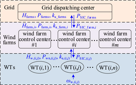
FIGURE 2. Structure of cooperative synthetic inertia control for wind farms.
FR Capability Evaluation Method
FR Capability Evaluation Method for Single D-PMSG
Generally, the D-PMSG’s FR capability is related to the wind condition and operating state. Under PDSIC mode, D-PMSG’s FR capability is related to the rotor kinetic energy and the adjustable capacity of converter.
Limited by the rotor kinetic energy of the D-PMSG and the capacity margin of the converter during the system frequency falling or rising, the D-PMSG’s FR capability can be quantitatively evaluated by
where ka is the FR capability coefficient defined in (Shi et al., 2016), varying from [0, 1], and a is the per unit of the rotor speed, i.e. a =
The relationship between the FR capability coefficient ka and the rotor speed
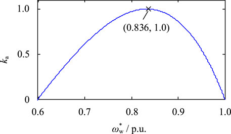
FIGURE 3. D-PMSG’s FR capability coefficient versus rotor speed.
FR Capability Evaluation Method for Single Wind Farm
The FR capability coefficient ka reflects the operating state. However, the FR capability of single wind farm is not only related to the operating state of D-PMSGs, but also their parameters, such as the rated capacity Pwn and the inertia constant Hw.
To evaluate the FR capability for single wind farm, a wind farm containing n D-PMSGs can be equal to a synchronous generator with a rated power Pfarmn, i.e.
where Pwn, i is the rated power of the i-th D-PMSG.
Considering that 1) the rotor kinetic energy Ekn of D-PMSG operating at rated speed is equal to the product of Pwn and Hw and 2) rotational kinetic energy is identical before and after equivalence, the FR capability coefficient ka_farm for the equivalent wind farm can be expressed as
where ka, i and Hw, i are the FR capability coefficient [see (6)] and the inertia constant of the i-th D-PMSG respectively, and Hfarm is inertia constant of the equivalent wind farm, i.e.
Obviously, the range of ka_farm also is (0, 1) because of ka, i∈(0, 1). Specially, if the rated power and inertia constants of all D-PMSGs are equal respectively in a wind farm, (8) can be written as
From (8) and (10), when the parameters of all D-PMSGs keep constant, the FR capability of the wind farm is enhanced with the increase of the proportion of D-PMSGs operating at medium wind speed. Besides, when all D-PMSGs keep their operating states invariant, the larger rated power Pwn and the inertia time constant Hw are, the greater FR contribution of the D-PMSG in this wind farm.
FR Capability Evaluation Method for Multiple Wind Farms
Similarly, based on the principle of rotational kinetic energy keeping identical before and after equivalence, m wind farms participating in the system FR process can be equal to a synchronous generator. Thus, the FR capability coefficient of multiple wind farms ka_farms can be defined as
where ka_farm, i, Pfarmn, i, and Hfarm, i are FR capability coefficient, total rated power, and equivalent inertia constant of the i-th wind farm respectively; Pfarmsn and Hfarms are the total rated power and equivalent inertia constant of the m wind farms, and their expressions are
Obviously, the ka_farms also is in (0, 1) because of ka_farm, i ∈ (0, 1).
Principle of Cooperative Synthetic Inertia Control for Wind Farms
By regarding m wind farms involved in system FR process as an equivalent WT and considering the FR capability of wind power, the auxiliary FR power of multiple wind farms based on the traditional PDSIC can be expressed as
where kp_farms and kd_farms are SIC coefficients, which can be calculated by
In power system, the auxiliary FR power of the i-th wind farm PSIC_farm, i is determined by its FR capability coefficient ka_farm, i and rotor kinetic energy of equivalent WT operating at rated speed, namely
In the i-th wind farm, the j-th D-PMSG’s auxiliary FR power PSIC (i,j) is determined by its FR capability coefficient and the rotor kinetic energy at rated speed, namely
Substituting (15) into (16) gives PSIC (i, j) as
From the above distribution process of auxiliary FR power, the cooperative control achieves auxiliary FR power distribution according to the FR capability of D-PMSG and wind farm.
Cooperative Rotor Speed Recovery Control of D-PMSG Between Different Wind Farms
After the system FR process of D-PMSG controlled by SIC mode, the change of rotor kinetic energy causes rotor speed to deviate from its optimal rotor speed calculated by MPPT control and reduces its power generation efficiency. Therefore, an effective rotor speed recovery control is required to make the D-PMSG operate at optimal speed in time.
The essence of the rotor speed recovery control is to gradually reduce the auxiliary FR power PSIC to 0, thus providing an acceleration torque towards the optimal rotor speed. This paper proposes a rotor speed recovery control implemented by directly compensating the auxiliary FR power PSIC calculated by the SIC module, and the principle of proposed control is shown in Figure 4. Obviously, the compensated power ΔPREC can be obtained by
where fREC(t) is the compensation function and determines rotor speed recovery process.
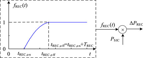
FIGURE 4. Rotor speed recovery control based on direct compensation of auxiliary FR power.
To reduce the secondary impact of D-PMSG rotor speed recovery process on the system frequency, the response characteristics of the conventional synchronous generator governor are considered in this paper. The optimized quadratic function is used for power compensation control. By introducing the start time of the rotor speed tREC, on and duration of the rotor recovery process TREC, the flexible control of the rotor speed recovery process is realized. The compensation function fREC(t) is
where tREC, on is the start time of the rotor speed recovery control and TREC is the duration of the rotor recovery process.
Obviously, during the system FR process, the different start time and duration of rotor speed recovery have different effects on the system frequency. Since the system inertia response process is usually around 5–10 s, the rotor speed recovery control should be enabled within 5–10 s after the start of SIC. A larger TREC can reduce the secondary impact of the rotor speed recovery on the system frequency; however, it also can reduce the speed of rotor speed recovery, resulting in a long recovery time. Therefore, the determination of TREC is required a compromise between the time of rotor speed recovery and the secondary impact on system frequency. Considering the primary frequency regulation usually within 10–30 s, the duration TREC can be set as around 30 s.
For multiple wind farms participating in system FR process, they can be equated to an equivalent WT whose compensation power ΔPREC_farms during the rotor speed recovery process is
Similar to (17), for the j-th D-PMSG in the i-th wind farm, the speed recovery compensation power ΔPREC (i,j) can be obtained by
According to (17) and (21), during rotor speed recovery process, the auxiliary FR power command eventually received by the D-PMSG is
Considering the rotor speed recovery process, the structure is shown in Figure 5.
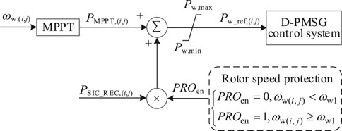
FIGURE 5. Structure of CSIC considering the rotor speed recovery process.
Although the start time and duration of the rotor speed recovery process are the same for all D-PMSGs in a wind farms, the output power of the wind farms can change smoothly due to the compensation function, thus effectively avoiding a secondary frequency drop.
Realization of CSIC for Wind Farms
In actual engineering, if the cooperative synthetic inertia control for wind farms shown in Figure 2 is strictly implemented, on the one hand, the real-time communication burden is increased by a large amount of data between the D-PMSG, the wind farm control center and the grid dispatching center; on the other hand, limited by the communication delay, the response speed of the D-PMSG controlled by PDSIC mode is weakened. To meet the requirements for rapidity of D-PMSG participating in inertia regulation and transient primary frequency control, ignoring the delay (the ideal situation) in the process from D-PMSG operating states summary to FR power distribution, this paper analyzes the essence of CSIC and proposes a new realization method of CSIC for wind farms considering FR capability based on the cooperative control shown in Figure 2.
Firstly, the cooperative coefficient ζfarms is defined by D-PMSG inertia constant and equivalent inertia constant of the wind farms involved in the system FR process, namely
By substituting (13) (14), and (23) into (17), the auxiliary FR power of the j-th D-PMSG in the i-th wind farm controlled by CSIC mode can be expressed as
where kp and kd can be calculated by (4).
Similarly, substituting (13) (14), and (23) into (22) gives the above FR power considering the rotor speed recovery as
From (24), the cooperative control for multiple D-PMSGs is achieved by the FR capability coefficient ka and cooperative coefficient ζfarms. Specially, ka reflects the real-time state of D-PMSG, which D-PMSG can adjust the degree of participating in FR according to its operating state; ζfarms characterizes the relative size of the inertia of single D-PMSG and the equivalent inertia of the wind farms, which D-PMSG can further adjust the degree of participation according to its relative FR capability, thus achieve cooperative control for multiple D-PMSGs. Besides, ζfarms increases with increase the D-PMSG inertia constant of [see (23)], and FR power and contribution of D-PMSG are larger in the wind farm [see (24) or (25)].
Based on (4) and (25), Figure 6 shows realization of CSIC considering FR capability.
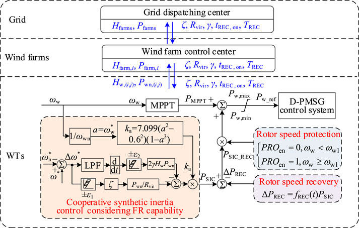
FIGURE 6. Realization of CSIC considering FR capability.
If only one wind farm participates in system FR process, the D-PMSG cooperative coefficient ζfarm is
For the realization of CIVC considering FR capability in Figure 6, except the D-PMSG’s inherent parameters Pwn and Hw, the superior dispatching center only sends the droop control coefficient Rvir, the equivalent inertia constant Hfarm or Hfarms, the synthetic inertia coefficient γ, and the start time tREC, on and the duration TREC of the rotor speed recovery control. Besides, the cooperative coefficient ζfarm can be adjusted by updating Hfarm or Hfarms, the control performance can be adjusted by updating Rvir and γ, and the rotor speed recovery process can be adjusted by updating tREC, on and TREC.
Because the superior dispatching center only sends control parameters, a high communication rate between the control center and D-PMSG is not required and the interval of issuing commands can be set to the second level. Even in extremely severe case, such as communication interruption, the D-PMSG can still automatically participate in the system FR process according to the control parameters previously provided by the control center.
Compared with the cooperative control in Figure 2, based on the frequency control parameters sent by the superior dispatching center, the proposed CSIC in Figure 6 directly responds to the system frequency variation and avoids the impact of the communication delay, thus achieving the best control performance (i.e. the ideal situation) for the method in Figure 2. Besides, due to without the process from D-PMSG operating state summary to FR power distribution, the implement of CSIC is simplified and its efficiency is increased. The comparison of CSIC characteristics shown in Figure 2 and Figure 6 is shown in Table 1.

As a matter of fact, small frequency fluctuations often caused by the changes of load and power supply, can be confronted by the utility grid independently. Therefore, for serious frequency problems caused by large or abnormal load disturbances, the D-PMSG participates in system FR process; otherwise for small frequency fluctuations, the D-PMSG should keep the original operating state determined by MPPT control to ensure the power generation efficiency. To this end, the action dead zone is set in Figure 6, which D-PMSG participates in system FR process only when the frequency exceeds the range [fn-ε1, fn+ε1] and the RoCoF (|df/dt|) exceeds its threshold ε2.
Simulation Verification
Simulation System
To verify the effectiveness and correctness of the CSIC for wind farms considering FR capability, the 2-area grid connected wind farms simulation model based on Matlab/Simulink is established in Figure 7. This system shortens the length of the transmission lines between two areas on the standard 4-machine 2-area system, thus enhancing the coupling relationship between the two areas.
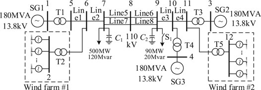
FIGURE 7. Simulation system model.
The simulation system consists of 1) three synchronous generators equipped with governor and exciter (34) and 2) two wind farms, each of which includes 90 D-PMSGs with the parameters of rated capacity 2 MW, rated wind speed 11.36 m s−1, and the rated rotor speed 1.98 rad s−1. However, the wind conditions and the D-PMSG inertia constants are different for the two wind farms, as shown in Table 2.
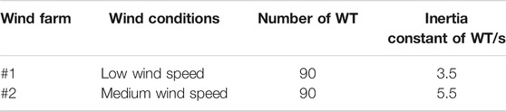
TABLE 2. Wind farm parameters and wind conditions.
For two wind farms, according to the size of MPPT control power, the wind speed is divided into low, medium and high wind speed, corresponding to 3 m s−1 ≤ v ≤ 8 m s−1, 8 m s−1 < v ≤ 10 m s−1 and 10 m s−1 < v ≤ 25 m s−1, where the cut-in wind speed is 3 m s−1 and the cut-out wind speed is 25 m s−1. For comparison, the D-PMSGs are divided into six groups, corresponding to wind speed: 7, 8, 9, 10, 11, and 12 m s−1, which the wind speeds of D-PMSGs in a group are same. The distribution of D-PMSGs in two wind farms is shown in Figure 8.
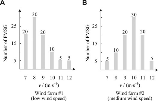
FIGURE 8. Distribution of D-PMSGs operating in different wind speeds.
During the stable operation, the system frequency is 50 Hz and the operation state of D-PMSG is determined by MPPT control. At t = 5 s, with switch S1 closed at node 9, the active load suddenly increases from 500 to 590 MW.
Simulation Case
To comparatively analyze, the simulation system is operated in four cases.
Case I: wind farm #1 and wind farm #2 are respectively replaced by a synchronous generator with the same capacity as wind farm (SG4, rated capacity 180 MW, inertia constant H = 3.5 s; SG5, rated capacity 180 MW, inertia constant H = 5.5 s), and the other parameters of G4 and SG5 is same with other SGs, namely the droop coefficient is 0.05.
Case II: the wind farm only uses MPPT control without SIC, i.e. D-PMSG is not involved in the system frequency response.
Case III: the wind farm is controlled by conventional PDSIC mode with Rvir= 0.05 and γ = 1.
Case IV: the wind farm is controlled by CSIC mode shown in Figure 6 with Rvir= 0.025, γ = 2, and Hfarms= 4.0 s.
The lower limit of rotor speed protection ωw1 is 0.6 p. u. in Case III and Case IV. For the rotor speed recovery control in Case IV, it is enabled after 5 s of the load disturbance (i.e. at t = 10 s), and the duration of rotor speed recovery process TREC is 35 s. Besides, the dead zone of CIVC is set as 49.9–50.1 Hz and ε2= 0.2%.
Analysis of Simulation Results
Response Characteristics
In this section, under the wind conditions shown in Figure 8, the performance of proposed control is analyzed from three aspects: system frequency response characteristics, wind farm response characteristics and D-PMSG response characteristics.
(1) System frequency response characteristics.
The system frequency response characteristics in four cases are shown in Figure 9, and the minimum fmin and relative improvement value ∆f of the system frequency are shown in Table 3.
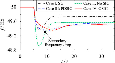
FIGURE 9. System frequency response characteristics in four cases.
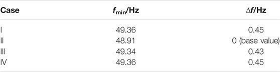
TABLE 3. Minimum and relative improvement value of the system frequency in four cases.
In Figure 9, the RoCoF indicator in Case I and Case IV are similar. In Table 3, the relative improvement value is of system frequency 0.43 Hz in Case III, while that is 0.45 Hz in Case I and Case IV. Therefore, in terms of suppressing the RoCoF and maximum frequency deviation, the CSIC can make the wind farm exhibit a transient FR capability which is comparable to that of a synchronous generator with same capacity and inertia. Besides, the conventional PDSIC results in a secondary frequency drop, while the CSIC not only effectively avoids that drop but also further improves the minimum value of system frequency (by 0.02 Hz).
2) Wind farms response characteristics.
During the transient response process, the FR capability coefficient and output power of each wind farm are shown in Figure 10 where PB represents the system base power.
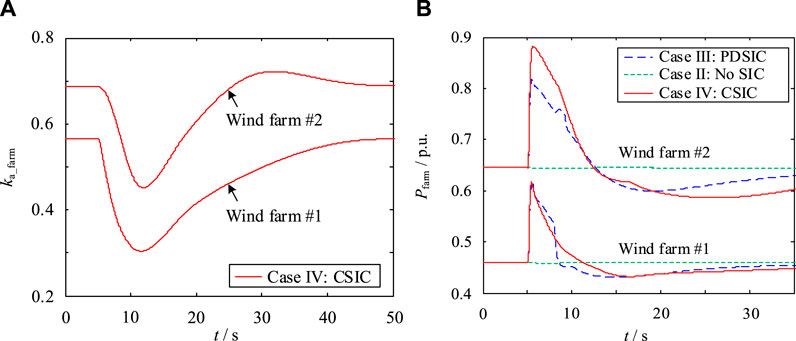
FIGURE 10. Response characteristics of two wind farms: (A) FR capability coefficient; (B) output power (PB = 180 MW).
In Figure 10A, the FR capability of wind farm #2 is stronger than that of wind farm #1, which it indicates that the FR capability is related to wind speed. In Figure 10B, under conventional PDSIC (Case III), due to ignoring the difference of FR capability between D-PMSGs, the maximum auxiliary FR power of each wind farm is almost identical. However, due to the poor wind conditions and the low inertia, rotor speed protections of some D-PMSGs are triggered and output power of wind farm rapidly decreases, causing FR power falling of wind farm #1, thus inducing the secondary frequency drop in Figure 9.
Under the CSIC for wind farms (Case IV), although the FR capability coefficient of wind farm ka_farm is not used in the actual control, due to the introduction of the FR capability coefficient ka of D-PMSG and the cooperative coefficient ζ [see (25)], the wind farms can participate in system FR process according to their FR capabilities, thus realizing the cooperative control between different wind farms.
3) D-PMSGs response characteristics.
For the D-PMSG controlled by two SIC modes (PDSIC and CSIC), the output power and rotor speed characteristics of D-PMSGs operating at different wind speeds in wind farm #1 are shown in Figure 11 and Figure 12 respectively.
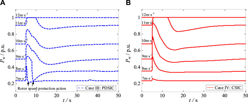
FIGURE 11. Output power of D-PMSGs operating at different wind speeds in (A) Case III and (B) Case IV (wind farm #1).
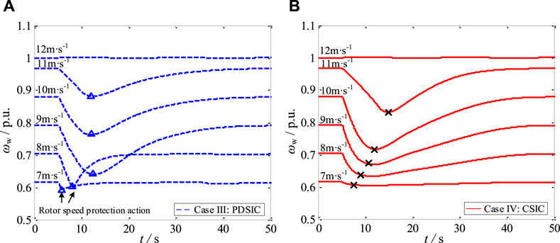
FIGURE 12. Rotor speed of D-PMSGs operating at different wind speeds in (A) Case III and (B ) Case IV (wind farm #1).
According to Figure 11 and Figure 12, because the traditional PDSIC mode ignores D-PMSG’s operating state, the low wind speed D-PMSGs excessively participate in system FR process and trigger their rotor speed protections, while the medium and high wind speed D-PMSGs cannot exert their abundant rotor kinetic energy and only cause small rotor speed fluctuations. However, under the CSIC mode, the D-PMSGs operating at different wind speeds provide different auxiliary FR power. In this way, the CSIC realizes the cooperative FR power distribution and cooperative rotor speed recovery between different D-PMSGs, effectively avoiding rotor speed protection action.
For the D-PMSG controlled by CSIC mode, Figure 13 shows the response characteristics of D-PMSGs operating at different wind speeds in two wind farms. For one thing, in the same wind farm, although the D-PMSGs’ parameters are same, each D-PMSG auxiliary FR power is different due to the different wind speed. For another thing, in different wind farms, although the initial operating state and rated capacity both are identical for D-PMSG operating at the same wind speed, the FR process of each D-PMSG is different due to different inertia constant. Besides, the larger D-PMSG inertia constant is, the more FR power and FR contribution are.
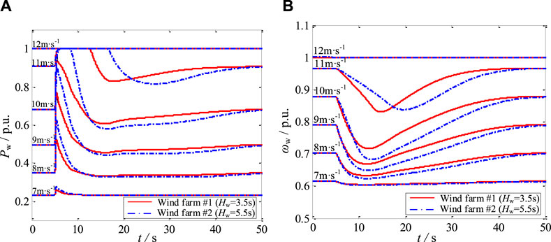
FIGURE 13. Response characteristics of D-PMSGs operating at different wind speeds in two wind farms in Case IV: (A) output power and (B) rotor speed.
Therefore, by introducing the FR capability coefficient and the cooperative coefficient, the power system can achieve the cooperative synthetic inertia control between different wind farms and different D-PMSGs from system and unit level.
Effect of Wind Conditions on the Frequency Response Characteristics
To further analyze the effect of wind conditions on the frequency response characteristics, the wind conditions for both wind farms are adjusted and shown in Figure 14.
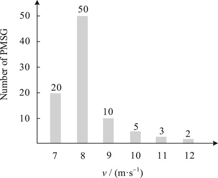
FIGURE 14. Same distribution of D-PMSGs operating at different wind speeds in two wind farms.
During system load disturbance in different cases, the system frequency response characteristics and the wind farm output power characteristics are shown in Figure 15. Compared to the conventional PDSIC, the proposed CSIC mode improves the frequency nadir from 49.15 to 49.27 Hz (See Figure 15). Besides, by comparing Figure 9 and Figure 15A, when the proportion of low wind speed D-PMSG in the wind farm increases, the more serious secondary frequency drop is caused under the conventional PDSIC mode, while that drop is avoided efficiently under the CSIC mode again.
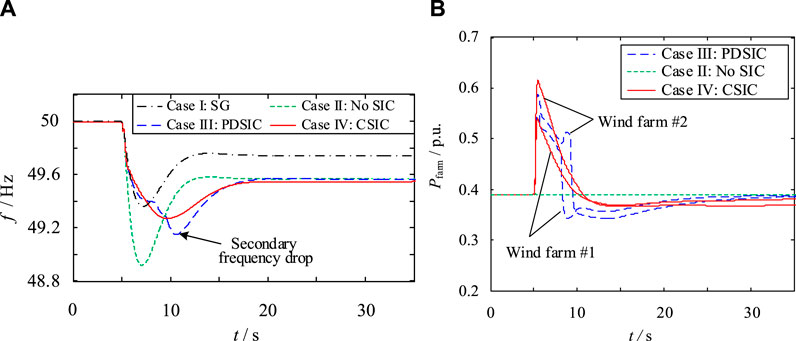
FIGURE 15. Response characteristics of power grid and wind farms in four cases: (A) system frequency response characteristics; (B) output power of two wind farms.
Conclusion
This paper firstly studies the FR capability evaluation method for single and multiple wind farms, analyzes the essence of CSIC and the rotor speed recovery. Based on these, the CSIC for wind farms considering FR capability is proposed, and simulation results verify the effectiveness and feasibility of the proposed method.
The FR capability of wind farm is related to the operating state and the parameter of WT. Based on the principle of equal rotational kinetic energy, this paper proposes the FR capability evaluation method for single and multiple wind farms, which can reasonably reflect the effect of operating state and the parameter of WTs on system FR process.
For the proposed CSIC for wind farms, by introducing FR capability coefficient and cooperative coefficient, the WT can participate in the system frequency response cooperatively according to its operating state and FR capability; by cooperative control between different WTs, the fast response performance of SIC is ensured and the communication requirement for wind farm control center is also reduced. Besides, by introducing compensation function, the rotor speed recovery control can avoid the secondary frequency drop and a complex schedule of rotor speed recovery for multiple WTs.
Data Availability Statement
The original contributions presented in the study are included in the article/Supplementary Material, further inquiries can be directed to the corresponding author.
Author Contributions
Conceptualization, QS and YW; Data curation, QS and QZ; Formal analysis, QS and LL; Funding acquisition, QS; Investigation, QS, LL and YW; Methodology, QS and LL; Project administration, QS, Y. Wang and QZ; Resources, QS, HL and QZ; Software, QS, HL and YL; Supervision, QS and YL; Validation, QS and QZ; Visualization, QS; Writing - original draft, QS and LL; Writing - review andamp; editing, QS and LL.
Funding
This work was supported by the National Key R&D Program of China (2016YFB0900600) and Science and Technology Projects of State Grid Corporation of China (52094017000W; SGNC0000TJJS2000470).
Conflict of Interest
The authors QR, YW, YL, QZ, QZ, were employed by NR Electric Co., Ltd.
The remaining authors declare that the research was conducted in the absence of any commercial or financial relationships that could be construed as a potential conflict of interest.
Publisher’s Note
All claims expressed in this article are solely those of the authors and do not necessarily represent those of their affiliated organizations, or those of the publisher, the editors and the reviewers. Any product that may be evaluated in this article, or claim that may be made by its manufacturer, is not guaranteed or endorsed by the publisher.
Acknowledgments
The authors wish to thank the project funding from National Key R&D Program of China (2016YFB0900600) and Science and Technology Projects of State Grid Corporation of China (52094017000W; SGNC0000TJJS2000470).
Supplementary Material
The Supplementary Material for this article can be found online at: https://www.frontiersin.org/articles/10.3389/fenrg.2021.738857/full#supplementary-material
References
Attya, A. B., Dominguez-Garcia, J. L., and Anaya-Lara, O. (2018). A Review on Frequency Support Provision by Wind Power Plants: Current and Future Challenges. Renew. Sustainable Energ. Rev. 81, 2071–2087. doi:10.1016/j.rser.2017.06.016
Bevrani, H., Ghosh, A., and Ledwich, G. (2010). Renewable Energy Sources and Frequency Regulation: Survey and New Perspectives. IET Renew. Power Gener. 4 (5), 438–457. doi:10.1049/iet-rpg.2009.0049
Bonfiglio, A., Invernizzi, M., Labella, A., and Procopio, R. (2019). Design and Implementation of a Variable Synthetic Inertia Controller for Wind Turbine Generators. IEEE Trans. Power Syst. 34, 754–764. doi:10.1109/tpwrs.2018.2865958
Chang-Chien, L.-R., Lin, W.-T., and Yin, Y.-C. (2011). Enhancing Frequency Response Control by DFIGs in the High Wind Penetrated Power Systems. IEEE Trans. Power Syst. 26 (2), 710–718. doi:10.1109/tpwrs.2010.2052402
Chang-Chien, L. R., and Yin, Y. C. (2009). Strategies for Operating Wind Power in a Similar Manner of Conventional Power Plant. IEEE Trans. Energ. Convers. 24 (4), 926–934. doi:10.1109/tec.2009.2026609
Chinchilla, M., Arnaltes, S., and Burgos, J. C. (2006). Control of Permanent-Magnet Generators Applied to Variable-Speed Wind-Energy Systems Connected to the Grid. IEEE Trans. Energ. Convers. 21 (1), 130–135. doi:10.1109/tec.2005.853735
Conroy, J. F., and Watson, R. (2008). Frequency Response Capability of Full Converter Wind Turbine Generators in Comparison to Conventional Generation. IEEE Trans. Power Syst. 23 (2), 649–656. doi:10.1109/tpwrs.2008.920197
deAlmeida, R. G., Castronuovo, E. D., and PecasLopes, J. A. (2006). Optimum Generation Control in Wind Parks when Carrying Out System Operator Requests. IEEE Trans. Power Syst. 21 (2), 718–725. doi:10.1109/tpwrs.2005.861996
Dreidy, M., Mokhlis, H., and Mekhilef, S. (2017). Inertia Response and Frequency Control Techniques for Renewable Energy Sources: A Review:a Review. Renew. Sustainable Energ. Rev. 69 (69), 144–155. doi:10.1016/j.rser.2016.11.170
Entso-Eaisbl, Brussels, Belgium, Tech (2019). Rep. "European Network of Transmission System Operators for Electricity (ENTSO-E) and Operators for Electricity. Continental Europe Significant Frequency Deviations. Available at https://eepublicdownloads.entsoe.eu/clean-documents/news/2019/190522_SOC_TOP_11.6_Task%20Force%20Significant%20Frequency%20Deviations_External%20Report.pdf
Francisco, D., Melanie, H., and Andreas, S. (2014). Participation of Wind Power Plants in System Frequency Control: Review of Grid Code Requirements and Control Methods. Renew. Sustainable Energ. Rev. 34, 551–564. doi:10.1016/j.rser.2014.03.040
Freitas, W., Xu, W., Affonso, C. M., and Huang, Z. (2005). Comparative Analysis Between RoCoF and Vector Surge Relays for Distributed Generation Applications. IEEE Trans. Power Deliv. 20 (2), 1315–1324. doi:10.1109/tpwrd.2004.834869
Hafiz, F., and Abdennour, A. (2015). Optimal Use of Kinetic Energy for the Inertial Support From Variable Speed Wind Turbines. Renew. Energ. 80, 629–643. doi:10.1016/j.renene.2015.02.051
Kheshti, M., Ding, L., Nayeripour, M., Wang, X., and Terzija, V. (2019). Active Power Support of Wind Turbines for Grid Frequency Events Using a Reliable Power Reference Scheme. Renew. Energ. 139, 1241–1254. doi:10.1016/j.renene.2019.03.016
Kv, V., and Senroy, N. (2013). Primary Frequency Regulation by Deloaded Wind Turbines Using Variable Droop. IEEE Trans. Power Syst. 28 (2), 837–846. doi:10.1109/TPWRS.2012.2208233
Li, Y., Xu, Z., Xiong, L., Song, G., Zhang, J., Qi, D., et al. (2019). A Cascading Power Sharing Control for Microgrid Embedded With Wind and Solar Generation. Renew. Energ. 132, 846–860. doi:10.1016/j.renene.2018.07.150
Liu, J., Golpîra, H., Bevrani, H., and Ise, T. (2021). Grid Integration Evaluation of Virtual Synchronous Generators Using a Disturbance-Oriented Unified Modeling Approach. IEEE Trans. Power Syst. 36 (5), 4660–4671. doi:10.1109/TPWRS.2021.3061615
Liu, K., Qu, Y., Kim, H.-M., and Song, H. (2018). Avoiding Frequency Second Dip in Power Unreserved Control During Wind Power Rotational Speed Recovery. IEEE Trans. Power Syst. 33, 3097–3106. doi:10.1109/tpwrs.2017.2761897
Lugovoy, O., Gao, S., Gao, J., and Jiang, K. (2021). Feasibility Study of China's Electric Power Sector Transition to Zero Emissions by 2050. Energ. Econ. 96, 105176. doi:10.1016/j.eneco.2021.105176
Morren, J., Pierik, J., and De-Haan, S. W. H. (2006). Inertial Response of Variable Speed Wind Turbines. Electric Power Syst. Res. 76 (2), 980–987. doi:10.1016/j.epsr.2005.12.002
Ping-Kwan Keung, P. K., Pei Li, P., and Banakar, H. (2009). Kinetic Energy of Wind-Turbine Generators for System Frequency Support. IEEE Trans. Power Syst. 24 (1), 279–287. doi:10.1109/tpwrs.2008.2004827
Ratnam, K. S., Palanisamy, K., and Yang, G. (2020). Future Low-Inertia Power Systems: Requirements, Issues, and Solutions - a Review. Renew. Sustainable Energ. Rev. 124, 109773. doi:10.1016/j.rser.2020.109773
Ravanji, M. H., Cañizares, C. A., and Parniani, M. (2020). Modeling and Control of Variable Speed Wind Turbine Generators for Frequency Regulation. IEEE Trans. Sustain. Energ. 11 (2), 916–927. doi:10.1109/tste.2019.2912830
Shi, Q., Wang, G., and Ma, W. (2016). Coordinated Virtual Inertia Control Strategy for D-PMSG Considering Frequency Regulation Ability. J. Electr. Eng. Technology. 11 (3), 1921–1935. doi:10.5370/jeet.2016.11.6.1556
Van de Vyver, J., De Kooning, J. D. M., Meersman, B., Vandevelde, L., and Vandoorn, T. L. (2016). Droop Control as an Alternative Inertial Response Strategy for the Synthetic Inertia on Wind Turbines. IEEE Trans. Power Syst. 31, 1129–1138. doi:10.1109/tpwrs.2015.2417758
Wang, H., Liu, Y., Zhou, B., Voropai, N., Cao, G., Jia, Y., et al. (2020). Advanced Adaptive Frequency Support Scheme for DFIG under Cyber Uncertainty. Renew. Energ. 161, 98–109. doi:10.1016/j.renene.2020.06.085
Xiong, L., Liu, X., Liu, Y., and Zhuo, F. (2020). Modeling and Stability Issues of Voltage-Source Converter Dominated Power Systems: a review. In CSEE Journal of Power and Energy Systems. (Early Access), 1-18. doi:10.17775/CSEEJPES.2020.03590
Xiong, L., Li, Y., Zhu, Y., Yang, P., and Xu, Z. (2018). Coordinated Control Schemes of Super-Capacitor and Kinetic Energy of DFIG for System Frequency Support. Energies. 11 (1), 103. doi:10.3390/en11010103
Xiong, L., Liu, X., Zhang, D., and Liu, Y. (2021). Rapid Power Compensation-Based Frequency Response Strategy for Low-Inertia Power Systems. IEEE J. Emerg. Sel. Top. Power Electron. 9 (4), 4500–4513. doi:10.1109/jestpe.2020.3032063
Xiong, L., and Zhuo, F. (2013). A Novel DC Voltage Balancing Method for Cascaded STATCOM. Twenty-Eighth Annu. IEEE Appl. Power Electronics Conf. Exposition. 2013, 924–929. doi:10.1109/apec.2013.6520321
Xue, Y., and Tai, N. (2011). Review of Contribution to Frequency Control Through Variable Speed Wind Turbine. Renew. Energ. (25), 1671–1677. doi:10.1016/j.renene.2010.11.009
Zhang, K., Zhou, B., Or, S. W., Li, C., Chung, C. Y., and Voropai, N. I. (2021). Optimal Coordinated Control of Multi-Renewable-To-Hydrogen Production System for Hydrogen Fueling Stations. IEEE Trans. Ind. Applicat., 1. doi:10.1109/TIA.2021.3093841
Nomenclature
Cpmax power coefficient to the optimal power of wind turbine
fn rated frequency (Hz)
fREC(t) compensation function of the rotor speed recovery process
fmin minimum value of the system frequency (Hz)
Ek D-PMSG rotor kinetic energy (J)
Ekn D-PMSG rotor kinetic energy at rated rotor speed (J)
Ek1 D-PMSG rotor kinetic energy at the lower limit of rotor speed protection (J)
Jw rotational inertia of D-PMSG (kg·m2)
Hw inertia constant of D-PMSG (s)
Hfarm equivalent inertia constant of wind farm (s)
Hvir synthetic inertia constant of D-PMSG (s)
ka FR capability coefficient of D-PMSG
kC available capacity factor
kd differential control coefficients of synthetic inertia control for D-PMSG
kJ available rotor kinetic energy factor
kmax control coefficient of MPPT control
kp proportional control coefficients of synthetic inertia control for D-PMSG
Pw D-PMSG output power (Watt)
Pw_ref reference power of D-PMSG (Watt)
Pwn rated power of D-PMSG (Watt)
Pw1 D-PMSG output power at the lower limit of rotor speed protection (Watt)
Pfarmn rated power of the wind farm (Watt)
PMPPT output power of maximum power point tracking (MPPT) control (Watt)
PROen PDSIC enable signal
PSIC auxiliary FR power of wind D-PMSG (Watt)
PSIC_REC auxiliary FR power of consider the rotor speed recovery control (Watt)
r blade radius (m)
v wind speed (m/s)
Rvir virtual droop coefficient of the equivalent synchronous generator
tREC, on the start time of the rotor speed recovery control (s)
TREC r duration of the rotor recovery process (s)
ω angular frequency (rad/s)
ωw rotor speed of wind turbine (rad/s)
ωw1 minimum Angular velocity of D-PMSG during SIC (rad/s)
ωn rated angular frequency (rad/s)
∆f improvement value of the system frequency (Hz)
Δω* per unit value of system frequency deviation (p.u.)
ΔPREC compensated power of D-PMSG for the rotor speed recovery control (Watt)
λopt Tip speed ratio corresponding to the optimal power of wind turbine
ζfarm cooperative coefficient of the wind farm
γ synthetic inertia coefficient
ρ air density (kg/m3)
p differential operator
ε1, ε2 dead zone value
Subscripts and Superscripts
ref Reference value
farm wind farm
farms wind farms
n Rated value
* Per unit value
∆ Deviation value
Keywords: synthetic inertia control, frequency regulation capability evaluation, wind farm, cooperative control, frequency control
Citation: Shi Q, Liu L, Wang Y, Lu Y, Zou Q, Zhang Q and Liu H (2021) Cooperative Synthetic Inertia Control for Wind Farms Considering Frequency Regulation Capability. Front. Energy Res. 9:738857. doi: 10.3389/fenrg.2021.738857
Received: 09 July 2021; Accepted: 17 August 2021;
Published: 30 August 2021.
Edited by:
Liansong Xiong, Nanjing Institute of Technology (NJIT), ChinaReviewed by:
Liancheng Xiu, Wuhan University, ChinaZhang Donghui, Nanjing University of Aeronautics and Astronautics, China
Xiaokang Liu, Politecnico di Milano, Italy
Copyright © 2021 Shi, Liu, Wang, Lu, Zou, Zhang and Liu. This is an open-access article distributed under the terms of the Creative Commons Attribution License (CC BY). The use, distribution or reproduction in other forums is permitted, provided the original author(s) and the copyright owner(s) are credited and that the original publication in this journal is cited, in accordance with accepted academic practice. No use, distribution or reproduction is permitted which does not comply with these terms.
*Correspondence: Qiaoming Shi, c2hpcWlhb21pbmdAbnJlYy5jb20=