- Institute for Aerospace Studies, University of Toronto, Toronto, ON, Canada
This paper provides an extension to previous work on end-effector control of flexible space manipulators. Those works considered the use of a special output called the
1 Introduction
The control of structurally flexible robot manipulators represents a significant challenge when compared with that of their rigid counterparts. In the latter case, the desired motions of the end-effector position and orientation are easily translated into a prescription for the joint motions. The latter are typically collocated with torque actuation provided by motors. This leads to the desirable property of passivity for the input-output mapping relating joint torques to joint rates. The passivity theorem (Desoer and Vidyasagar, 1975) then guarantees the stability provided by the negative feedback of strictly passive controllers such as proportional-integral control applied to joint rates [i.e., proportional-derivative (PD) control applied to the joint angle motions].
For structurally flexible manipulators, the passivity property of the joint torque to joint rate mapping continues to hold given the collocation (Benhabib et al., 1981) but this is less useful because control of the joint motions does not necessarily produce the correct motion for the end-effector coordinates. However, it is fair to say that many researchers (Benosman and Le Vey, 2004) have opted to control flexible manipulators by tracking desired joint trajectories (obtained from rigid inverse kinematics) coupled with vibration suppression of the flexible coordinates. This is often misguided because the inverse kinematical solution for a prescribed end-effector motion does typically require some deformations of the links as shown by Bayo et al. (1989).
Robust control is necessitated when there is a need for stability despite model uncertainties and environmental disturbances. For flexible manipulators, a specific issue arises in terms of the model uncertainty created by uncertain vibration frequencies and mode shapes as well as different numbers of modes in the plant model used for design compared to those in the actual structure. The vast majority of models consider each link in the manipulator as a beam with a truncated set of modes. In most cases, this truncation is not an issue and is seen to agree well with experimental results, given an appropriate number of modes have been included in the model. In a few exceptional circumstances, however, cases of spillover instability have been seen to arise as seen in Sayahkarajy and Mohamed (2014). With the passivity theorem, simple controllers can be used to robustly control systems when model uncertainty does not destroy the passivity of the plant. Hence, if passivity is achievable, then the manipulator could be robustly stabilized by a simple PD controller despite having truncated numbers of modes in the dynamics modelling.
In task-space control, actuator and sensor collocation is not possible, and it has been shown in Pota and Vidyasagar (1991) that the input-output mapping relating joint torque to tip-rate is not passive for a single flexible link. This can be explained by the fact that the transfer matrix for this mapping is nonminimum phase (hence not positive real) as shown in Cannon Jr. and Schmitz (1984). With the actual tip-rate output not being viable for task-space control of flexible manipulators, past research has focused on finding alternative task-space outputs that could perhaps achieve passivity. Given the relative ease with which passive input-output pairs can be stabilized, there has been some work done on establishing passivity for systems whose output contains the end-effector motion.
Wang and Vidyasagar (1992) were able to effectively realize the passivity property for a single flexible link system by using a reflected tip-rate output and with the assumption that the moments of inertia produced by the link and payload are much greater than the moment of inertia of the hub. These results were extended in Damaren (1995) for a multi-degree-of-freedom space manipulator attached to a rigid spacecraft and with an end-effector payload. Damaren posed an modified tip-rate output,
where
where
With large payloads,
Obtaining the elastic coordinates through sensors has proven difficult, historically. In some experimental papers the elastic deflection of a flexible link is measured using optical sensors such as cameras as seen in Wang and Vidyasagar (1992) or laser diodes as seen in Tso et al. (2003). Notably, this was done for the single-link manipulator in both Wang and Vidyasagar (1992) and Tso et al. (2003). With multi-degree-of-freedom manipulators, these optical systems would be more expensive and complicated to implement and are less feasible. Another major problem with these optical sensing systems is that they become unusable if an object comes in between the camera and the manipulator. Another strategy is to use resistive strain gauges, which was done in Stanway et al. (1998) to obtain values for elastic coordinates experimentally. Christoforou and Damaren (2000) used strain gauges to estimate three flexible coordinates for each of two flexible links on a three-link planar manipulator. This required calibration of the strain gauges before each use of the manipulator system and was more labour-intensive overall. Additionally, strain gauges have reliability issues in the space environment due to thermal effects.
With the difficulty in measuring elastic coordinates directly, the next best solution would be to find a way to reliably estimate these coordinates. Then,
More recently, virtual sensor theory has been used to estimate the generalized elastic coordinates and find the end-effector position of flexible manipulators. This was done in Bengoa et al. (2017) very successfully though with a note on the computational load required for real-time implementation. In Adel et al. (2022) virtual sensor theory was combined with function approximation schemes found in machine learning literature. Results were also promising with this method although the computational load was still high, albeit lower than in Bengoa et al. (2017).
Overall, sensor solutions to measure elastic coordinates are lacking with current technology. Furthermore, most observer schemes to estimate these coordinates are either highly complex, so requiring a large computation load, or are not feasible for nonlinear systems in a space setting. In contrast, Damaren (1995) offers a closed-form estimation formula, valid for flexible manipulators with large payloads. It is given by
where
The present paper looks at the simulated behaviour of flexible robots in response to a task-space controller that uses the above estimate of the flexible coordinates to determine
2 Methods
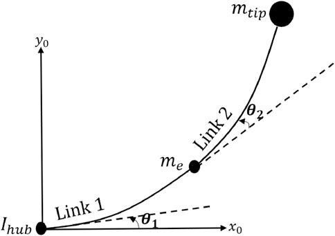
In this paper, a space robot comprised of a topological chain of
2.1 Equations of motion
The modelling techniques from Damaren (1995), Wong (2006), and Fraser and Daniel (1991) were used to develop the equations of motion. For a general flexible manipulator, these equations are as follows:
where
for the above matrices, the matrix structure is consistent with
where
2.2 Control scheme
With the equations of motion defined, a task-space control scheme can be implemented. This control scheme utilized the approximated elastic coordinates to determine the modified task-space output,
where
The modified tip-rate output is as follows:
the above equation assumes the true end-effector rate
If the Jacobian is approximated by
hence, for
additionally, it is to be noted that to use Equation 7, the rigid Jacobian is needed. In multi-degree-of-freedom manipulators, this Jacobian is a function of elastic coordinates and so the approximation must be used for computation of the term. Then Equation 7 can be rewritten as the following:
where
where
3 Results and discussion
3.1 One-link
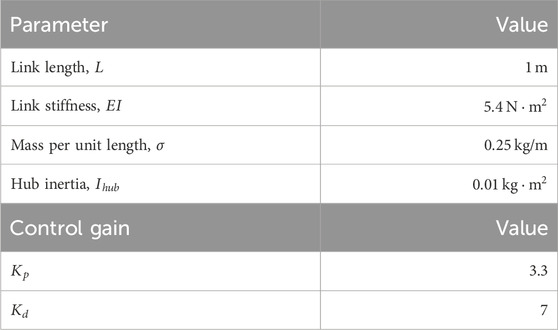
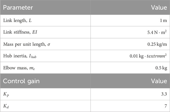
Multiple simulations were done in MATLAB implementing the control scheme given by Equation 6. Table 1 below lists the sizing parameters and control gains used in all one-link simulations.
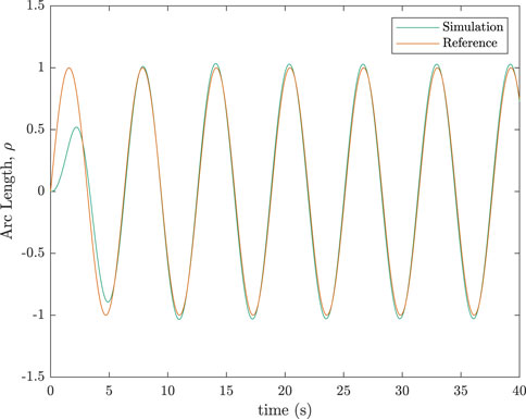
A sinusoidal trajectory was simulated for the one-link manipulator. Results are shown in Figure 3. The worst tracking occurred in the initial few seconds of the simulation. This follows from the fact that the approximation given by Equation 11 is derived assuming a quasi-static state, whilst the period when the manipulator is first moved from rest is highly dynamic. Figure 3 includes results from an appropriate joint-space control scheme as well, for easier comparison. The following joint-space control scheme was used:
Note that the desired joint angle, rate, and acceleration used in the joint-space scheme were obtained from the rigid inverse kinematic solution of the desired end-effector trajectory. The task-space scheme using the elastic coordinate approximation fared much better than the joint-space scheme as seen in the simulation results in Figure 3. The proportional and derivative gains,
Figure 4 shows the tracking error for this same simulation. The two graphs of
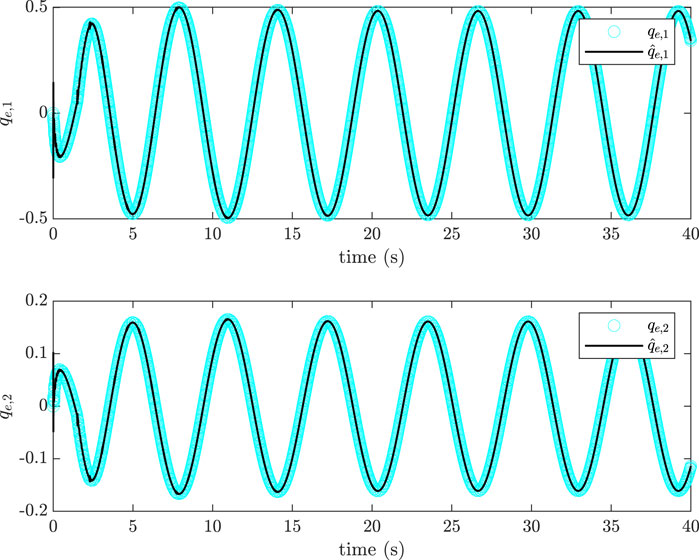
Figure 5. Comparison of approximated generalized elastic coordinates with actual, simulated values,
The following equation was used to calculate the error between the actual elastic coordinates and the estimated ones:
This error was calculated for multiple simulations, across which, the trajectory followed and the
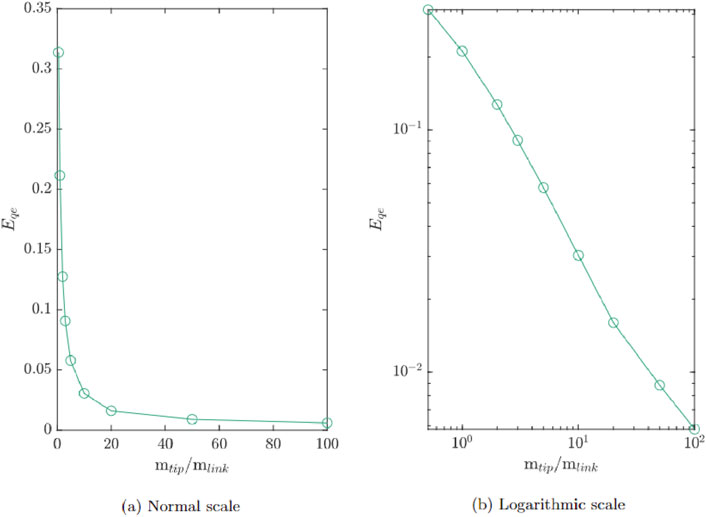
Figure 6. Generalized elastic coordinate estimation error on (A) normal scale and (B) logarithmic scale for varying ratios of
Notably, the elastic component of the link’s displacement was modelled using only two basic functions in all results thus far, hence the two elastic coordinates generated in Figure 5. As one issue with controlling flexible structures is their infinite elastic degrees of freedom, it is important to investigate if truncating these degrees of freedom to elastic modes caused a loss of stability.
To check this, a simulation was done where the number of degrees of freedom in the controller was set to be different from the number in the plant. All terms in Equation 6 were calculated using a truncated model of two flexible degrees of freedom,
3.2 Two-link
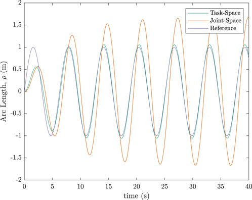
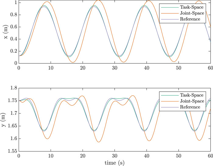
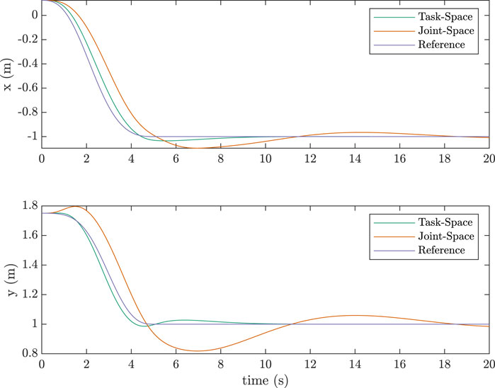
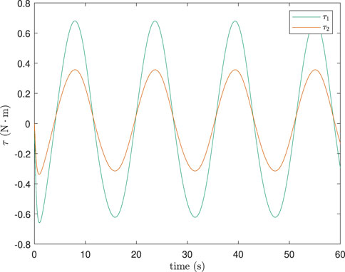
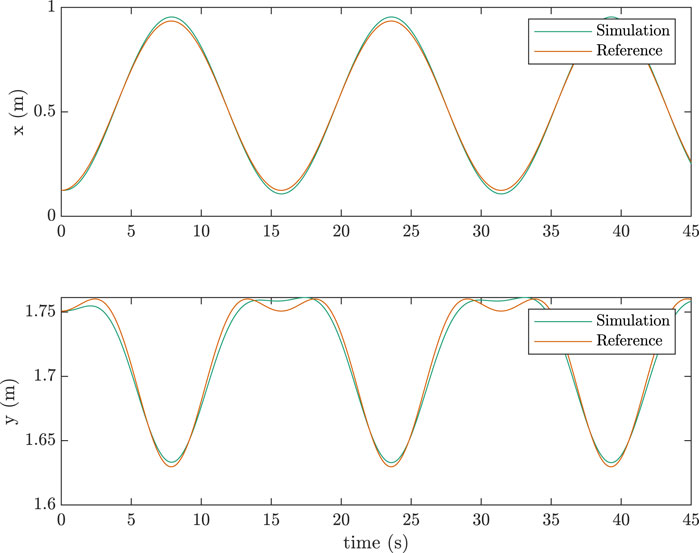
Simulations for the two-link case were also done similarily. Table 2 lists the parameters used in the simulations along with the control gains.Figure 8 shows the task-space tracking as compared to a joint-space scheme for a sinusoidal trajectory. Figure 9 shows the equivalent for a pick-and-place trajectory generated using a quintic polynomial. The performance with the task-space scheme proved to be considerably better than its joint-space counterpart for both trajectory types. The joint-space scheme used in Figures 8, 9 is as follows:
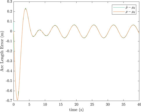
As tracking performance for the two-link case was slightly worse than the one-link case, especially for the sinusoidal trajectory, an investigation was done to see how much of this performance loss was due to the elastic coordinates being estimated rather than measured. Figures 10, 11 show the tracking error for both the sinusoidal and pick-and-place trajectories, respectively. As one can see, the graphs of
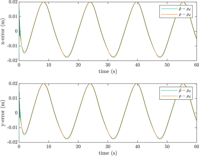
Figure 10. Error between true tip-position and desired position for a two-link manipulator, sinusoidal trajectory,
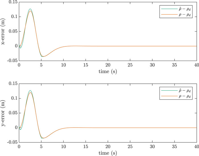
Figure 11. Error between true tip-position and desired position for a two-link manipulator, quintic trajectory,
The slight oscillations visible in Figure 10 at the beginning of the simulation can be explained by the assumptions behind the approximation equation, namely that it was derived in Damaren (1995) assuming a quasi-static state of the manipulator. When the manipulator is first moved from rest, it is highly dynamic and the approximation equation is not able to estimate the elastic coordinates as accurately in this initial highly dynamic period. This explains the deviations present at the beginning of Figure 10.
As the Jaocbians in the two-link case are a function of
To bypass the need to use the approximated elastic coordinates of the previous time-step in the calculation of the current
Equations 1, 2, 4, 5, 9, 12-15 summarize the kinematics, dynamics, and control. In Figures 12, 13, corresponding to the sinusoidal and pick-and-place trajectories, respectively, the approximate elastic coordinates,
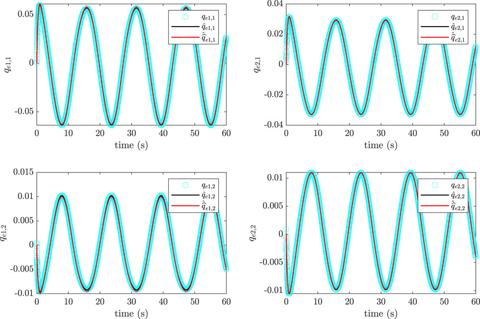
Figure 12. Comparison of approximated generalized elastic coordinates with actual, simulated values for two-link manipulator, sinusoidal trajectory,
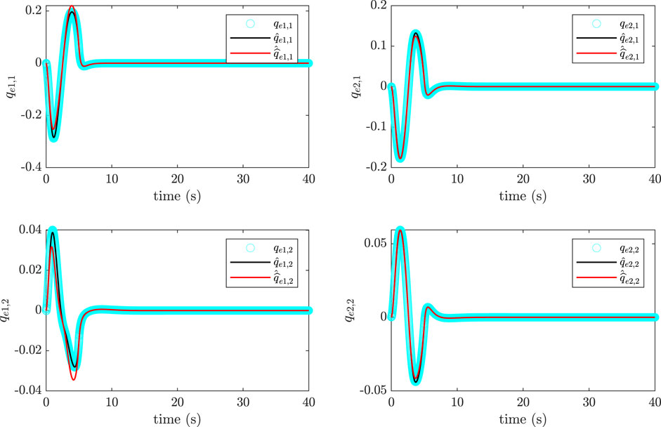
Figure 13. Comparison of approximated generalized elastic coordinates with actual, simulated values for two-link manipulator, quintic trajectory,
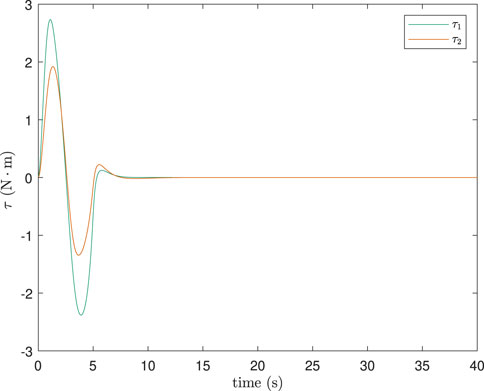
Lastly, simulations were done with a different number of modes for the plant and controller to check if truncating the dynamics to a finite dimension caused instability. Results showed no spillover effects as shown in Figure 16 below. The total number of elastic modes used were
4 Conclusion
In this work, one-link and two-link flexible manipulators were modelled and a task-space control scheme that utilized the passivity theorem was implemented for end-effector trajectory tracking. This tracking was accomplished using the elastic coordinate approximation given by Equation 11. In all cases, the
In the one-link results, it was seen that the elastic coordinate approximation given by Equation 11 was more accurate as the ratio of
Data availability statement
The raw data supporting the conclusions of this article will be made available by the authors, without undue reservation.
Author contributions
DP: Visualization, Writing–original draft, Writing–review and editing. CD: Supervision, Writing–original draft, Writing–review and editing.
Funding
The author(s) declare that financial support was received for the research, authorship, and/or publication of this article. This work was funded by a Discovery Grant provided by the Natural Sciences and Engineering Research Council (Canada).
Conflict of interest
The authors declare that the research was conducted in the absence of any commercial or financial relationships that could be construed as a potential conflict of interest.
The author(s) declared that they were an editorial board member of Frontiers, at the time of submission. This had no impact on the peer review process and the final decision.
Publisher’s note
All claims expressed in this article are solely those of the authors and do not necessarily represent those of their affiliated organizations, or those of the publisher, the editors and the reviewers. Any product that may be evaluated in this article, or claim that may be made by its manufacturer, is not guaranteed or endorsed by the publisher.
References
Adel, M., Ahmed, S. M., and Fanni, M. (2022). End-effector position estimation and control of a flexible interconnected industrial manipulator using machine learning. IEEE Access 10, 30465–30483. doi:10.1109/ACCESS.2022.3157817
Bayo, E., Papadopoulos, P., Stubbe, J., and Serna, M. A. (1989). Inverse dynamics and kinematics of multilink elastic robots: an iterative frequency domain approach. Int. J. Robotics Res. 8, 49–62. doi:10.1177/027836498900800604
Bengoa, P., Zubizarreta, A., Cabanes, I., Mancisidor, A., Pinto, C., and Mata, S. (2017). Virtual sensor for kinematic estimation of flexible links in parallel robots. Sensors 17 (9), 1934. doi:10.3390/s17091934
Benhabib, R. J., Iwens, R. P., and Jackson, R. L. (1981). Stability of large space structure control systems using positivity concepts. J. Guid. Control, Dyn. 4, 487–494. doi:10.2514/3.56100
Benosman, M., and Le Vey, G. (2004). Control of flexible manipulators: a survey. Robotica 22, 533–545. doi:10.1017/s0263574703005642
Bernard, P. (2017). Observer design for nonlinear systems, automatic control engineering. Paris, France: Université Paris sciences et lettres. Ph.D. thesis.
Cannon, Jr. R. H., and Schmitz, E. (1984). Initial experiments on the end-point control of a flexible one-link robot. Int. J. Robotics Res. 3, 62–75. doi:10.1177/027836498400300303
Chen, T., Wang, Y., Wen, H., and Kang, J. (2023). Autonomous assembly of multiple flexible spacecraft using RRT* algorithm and input shaping technique. Nonlinear Dyn. 111, 11223–11241. doi:10.1007/s11071-023-08445-3
Christoforou, E. G., and Damaren, C. J. (2000). The control of flexible-link robots manipulating large payloads: theory and experiments. J. Robotic Syst. 17, 255–271. doi:10.1002/(sici)1097-4563(200005)17:5<255::aid-rob3>3.0.co;2-k
Damaren, C. J. (1995). Passivity analysis for flexible multilink space manipulators. J. Guid. Control, Dyn. 18, 272–279. doi:10.2514/3.21380
Damaren, C. J. (2000). Passivity and noncollocation in the control of flexible multibody systems. J. Dyn. Syst. Meas. Control 122, 11–17. doi:10.1115/1.482423
Desoer, C. A., and Vidyasagar, M. (1975). Feedback systems: input-output properties. New York: Academic Press.
Fenili, A. (2013). The rigid-flexible robotic manipulator: nonlinear control and state estimation considering a different mathematical model for estimation. Shock Vib. 20, 1049–1063. doi:10.1155/2013/681846
Fraser, A. R., and Daniel, R. W. (1991). Perturbation techniques for flexible manipulators. Massachusetts: Kluwer Academic Publishers.
Moallem, M. (1996). Control and design of flexible-link manipulators. Montreal, Canada: Concordia University. Ph.D. thesis.
Pota, H., and Vidyasagar, M. (1991). Passivity of flexible beam transfer functions with modified outputs. Proc. 1991 IEEE Int. Conf. Robotics Automation 3, 2826–2831. doi:10.1109/robot.1991.132061
Sayahkarajy, M., and Mohamed, Z. (2014). Mixed sensitivity H2/Hinfinity control of a flexible-link robotic arm. Int. J. Mechani. Mechatron. Enginee. 14, 21–27. doi:10.1007/bf00932903
Stanway, J., Sharf, I., and Damaren, C. (1998). Comparison and validation of dynamics simulation models for a structurally flexible manipulator. ASME J. Dyn. Syst. Meas. Control 120, 404–409. doi:10.1115/1.2805417
Tso, S., Yan, T., Xu, W., and Sun, Z. (2003). Vibration control for a flexible-link robot arm with deflection feedback. Int. J. Non-Linear Mech. 38, 51–62. doi:10.1016/s0020-7462(01)00040-3
Wang, D., and Vidyasagar, M. (1992). Passive control of a stiff flexible link. Int. J. Robotics Res. 11, 572–578. doi:10.1177/027836499201100606
Keywords: flexible space manipulators, flexible coordinate estimation, tip control, vibration suppression, task-space control
Citation: Patel D and Damaren CJ (2024) Tip and vibration control of space robots using estimated flexible coordinates. Front. Space Technol. 5:1447545. doi: 10.3389/frspt.2024.1447545
Received: 11 June 2024; Accepted: 03 September 2024;
Published: 18 September 2024.
Edited by:
Ti Chen, Nanjing University of Aeronautics and Astronautics, ChinaReviewed by:
Zhengtao Wei, Nanjing University of Aeronautics and Astronautics, ChinaHuarong Zhao, Jiangnan University, China
Copyright © 2024 Patel and Damaren. This is an open-access article distributed under the terms of the Creative Commons Attribution License (CC BY). The use, distribution or reproduction in other forums is permitted, provided the original author(s) and the copyright owner(s) are credited and that the original publication in this journal is cited, in accordance with accepted academic practice. No use, distribution or reproduction is permitted which does not comply with these terms.
*Correspondence: Christopher J. Damaren, Y2hyaXMuZGFtYXJlbkB1dG9yb250by5jYQ==
 Dhruvi Patel
 Christopher J. Damaren
