
95% of researchers rate our articles as excellent or good
Learn more about the work of our research integrity team to safeguard the quality of each article we publish.
Find out more
ORIGINAL RESEARCH article
Front. Signal Process. , 27 March 2025
Sec. Audio and Acoustic Signal Processing
Volume 5 - 2025 | https://doi.org/10.3389/frsip.2025.1519450
This article is part of the Research Topic Sound Synthesis through Physical Modeling View all 4 articles
 Champ C. Darabundit*
 Gary Scavone
Time-domain simulation of woodwind instruments typically involves the development of separate discrete-time sub-models for the excitation mechanism and the resonator. These components have largely been modeled via digital waveguide or finite-difference time-domain (FDTD) methods. We present a separate approach based on the modular and energy-based port-Hamiltonian system (PHS) framework. We recast the three main components of a woodwind instrument—the single-reed, the bore, and the tonehole—as PHS models and incorporate novel elements in each derivation. In the beating reed model, we make use of recent work on energy quadratization to formulate a linearly implicit scheme of the nonlinear Hunt-Crossley contact force coupled to a nonlinear Bernoulli flow. In the horn model, we discretize a distributed PHS representing the horn equation with a generalized symplectic Störmer-Verlet scheme, verifying previously proposed FDTD schemes. In the tonehole model, we propose a new low-frequency model of the tonehole and model note transitions with a switching PHS. The benefit of describing each element as a PHS is demonstrated by the ability to interconnect all sub-models in a modular and energy-conserving manner to simulate a complete instrument. Simulations are performed on a test instrument and the numerical stability of the overall scheme is demonstrated.
Research into time-domain woodwind physical modeling synthesis began to coalesce with the publication of McIntyre, Schumacher, and Woodhouse’s seminal 1983 article (McIntyre et al., 1983). In their article, the authors demonstrate an efficient time-domain approach for modeling different musical instruments including the clarinet. The article also presents concepts that are found in physical modeling synthesis research to this day, namely, the subdivision of an instrument into modular components, including a nonlinear excitation model and a passive resonator model. In a woodwind instrument, these components correspond to the reed and the instrument bore, respectively. The methods proposed in McIntyre et al. (1983) were further developed in the field of computer music by digital waveguide (DWG) synthesis (Smith, 1986; Smith, 1992).
DWG synthesis is one of the most prevalent methods for modeling woodwind and brass instruments (Välimäki, 1995; Scavone, 1997; van Walstijn and Campbell, 2003; Mignot et al., 2010). DWG synthesis is based on a discretization of the traveling wave solution of the one-dimensional wave equation. The result is a digital system composed of delay lines—for propagating the traveling waves—and filters, for reflecting waves, modeling losses, and approximating fractional delay lengths. Reed dynamics are incorporated by modeling the reed-tip as a mass-spring-damper system (Scavone and Cook, 1998). The popularity of the DWG method can be attributed to its efficiency and the fact that the DWG models consist of delay lines and filters that fit naturally into the framework of digital signal processing (DSP). Another benefit of the DWG method is its modularity. A DWG model can be viewed as an interconnection of simpler component sub-models.
More recently, energy-based numerical simulation techniques using finite-difference time-domain (FDTD) methods have become a popular avenue for physical modeling synthesis (Bilbao, 2009). FDTD methods directly discretize the partial differential equations (PDEs) governing the physical model. In contrast, DWG methods rely on a discretization of analytical solutions to a system—as in the case of modeling wave propagation. This, however, typically limits the DWG method to modeling cylindrical or conical bore profiles with further limitations on the stability of the method for convex bore shapes (Berners, 1999). An approach to modeling bores with profiles that are
An alternative general energy-based modeling approach—and the focus of this article—is the port-Hamiltonian system (PHS) framework introduced in Maschke and van der Schaft (1993). PHSs combine energy-based analysis techniques within the Lagrangian and Hamiltonian framework from classical mechanics with the network modeling framework from electrical engineering (van der Schaft, 2006). The PHS framework provides a helpful procedure for the design and analysis of a continuous-time physical model as energy conservation is baked into the system formulation and models can be composed in a modular fashion (Duindam et al., 2009). PHSs have been primarily used to model nonlinear audio circuits in the related field of virtual analog (Falaize and Hélie, 2016a). Regarding physical modeling synthesis, PHSs have been used to model nonlinear strings (Hélie and Roze, 2016), electric pianos (Falaize and Hélie, 2017b), the lip-reed mechanism in brass instruments (Lopes and Hélie, 2016; Lopes, 2016), and a mobile vocal tract (Wetzel et al., 2019). While the PHS framework seems ideal for sound synthesis—the method is modular, energy-based, and formulated to be energy conserving—it is not without its drawbacks. To guarantee energy conservation in discrete PHSs, the primary discretization method is the discrete gradient method (Yalçin et al., 2015; Falaize and Hélie, 2016a). Higher-order methods for discretizing a PHS are discussed in Müller (2021). The discrete gradient method results in numerical dispersion, i.e., frequency warping, akin to the bilinear transform (Harrison-Harsley, 2018). For musical applications, this is undesirable as frequency warping can affect the tuning of simulated instruments. It is possible to minimize numerical dispersion through the careful design of explicit numerical schemes which are instead conditionally stable. Additionally, discrete PHSs in physical modelling synthesis are often relegated to lumped system modeling. Discrete distributed systems for modeling wave propagation have been handled using DWG (Lopes and Hélie, 2016) or modal decomposition techniques (Hélie and Roze, 2016; Falaize and Hélie, 2017b). However, modal decomposition is only valid for certain boundary conditions and if a decomposition exists.
The primary goal of this article is to present a PHS description of the three main components of a woodwind instrument: a lumped single-reed excitation mechanism, a one-dimensional bore model with variable cross-section based on the horn equation, and a lumped model of a tonehole. The secondary goal of this article is to draw similarities between the PHS and FDTD literature, presenting PHSs in a way that will be familiar to practitioners in the field of physical modeling synthesis and discretizing them with FDTD methods. Similar models of the reed, bore, and tonehole have been proposed based on FDTD methods in Chatziioannou et al. (2019); Bilbao and Harrison (2016) and DWG methods in van Walstijn and Scavone (2000), respectively and this article contributes refinements to these models. We include recent research on energy quadratization methods (Ducceschi et al., 2021; van Walstijn et al., 2024b) to design a linearly implicit scheme for the Hunt-Crossley contact in the reed system and propose a new low-frequency model of the tonehole that better approximates frequency-domain models in the literature. Energy conservation during note transistions is handled by modeling the tonehole as a switching PHS. We describe the lossy horn equation model proposed by Bilbao and Harrison (2016) as a distributed PHS and discretize the lossless wave propagation using the structure-preserving symplectic Störmer-Verlet method (Hairer et al., 2000), affirming the scheme used in their article. Furthermore, by characterizing each individual sub-model as a PHS we are able to interconnect each element in an energy-conserving and modular fashion and develop a system for modeling bores with arbitrary geometries and tonehole placements.
This paper is organized as follows: Section 2 will introduce port-Hamiltonian systems. Section 3 will discuss FDTD discretization methods and introduce the discrete gradient and Störmer-Verlet methods as FDTD methods. Section 4 provides an example of modeling and discretizing an RLC system model in the PHS framework. Section 5 will discuss the single-reed excitation including contact dynamics with the mouthpiece. Section 6 will present a distributed PHS model of the woodwind bore and Section 7 considers a model of the woodwind tonehole based on a switching PHS formulation. Section 8 will display simulation results with Section 9 concluding the article.
Port-Hamiltonian systems (PHSs), introduced in Maschke and van der Schaft (1993), approach physical modeling through the Hamiltonian equations of motion and combine these equations with network theory. The formalism provides a framework for a geometric description of models based on the interconnection of sub-systems through power-conserving interconnections (van der Schaft, 2006). As a consequence, energy conservation is baked into the PHS formulation through preservation of a power balance. Energy-conserving numerical methods—if discretized properly—will preserve passivity and avoid numerical instability. The PHS approach uses energy as a lingua franca between domains, making the framework well-suited for multi-physical simulations. Musical instruments are inherently multi-physical as the mechanical actions of the player are transformed into acoustic energy. Musical instruments are also inherently nonlinear. Nonlinearities such as the reed contact with the mouthpiece or the slip-stick action of a bowed string directly affect the perceived timbre of an instrument during performance (Chaigne and Kergomard, 2016). These reasons naturally motivate the use of PHSs for modelling musical systems. In the context of physical modeling, the PHS formalism is attractive because it provides a general form that can be used to characterize a variety of physical systems. This continuous-time formulation can then be discretized in a structured manner to produce a discrete-time numerical scheme.
In this section, we will review Hamiltonian dynamics and then the form of finite-dimensional PHSs. Theoretical specifics such as the definition of a Dirac structure are left out of this review. Instead, we circularly define Dirac structures as structures that preserve the power balance and are a consequence of Kirchhoff’s current and voltage laws. Interested readers are referred to the texts (van der Schaft, 2006; Duindam et al., 2009) and the tutorial (Hélie, 2022).
The Hamiltonian equations of motion for a system with
where
where
Port-Hamiltonian systems describe the interconnection of energy storage elements, energy dissipating elements, and power conserving elements using general power-conjugate variables of effort,
A useful representation of a dynamical PHS with state
Defining the total effort
where we have the block skew-symmetric matrix
Equation 5 states that the variation in the total stored energy is equal to the energy flowing in and out of the system,
We will also define a conjugate PHS where the variables
An important class of Hamiltonian functions are quadratic Hamiltonians. Quadratic Hamiltonian functions appear frequently in the systems we are interested in and have the following form and gradient,
where
Discretization methods are at the heart of any physical modeling synthesis algorithm and their design is of great importance. We will begin this section by first reviewing finite-difference time-domain (FDTD) methods, adopting the notation used in Bilbao (2009) for the rest of this article. We will first present the elementary discretization operators used in the design of numerical schemes and some useful identities given by Bilbao (2009). Then, we will present the two discretization methods used in this article. The first is the discrete gradient method, commonly used in PHS modeling, and the second is the symplectic Störmer-Verlet method. These methods are examples of mechanical integrators that preserve either the discrete energy or the symplectic form of the continuous-time system (Wendlandt and Marsden, 1997). The symplectic form is equivalent to the orientated area in state space. Symplecticity is a characteristic property of Hamiltonian systems and symplectic integrators are used to maintain this property in a numerical scheme (Hairer et al., 2000; Sanz-Serna and Calvo, 1994). It has been observed from numerical experiments (Chatziioannou, 2019) and backward error analysis (Hairer et al., 2003) that symplectic schemes provide a good discretization of a system’s dynamics at the expense of the discrete energy not being an exact sampling of the continuous-time energy function. Instead, a modified discrete energy function is conserved. In the physical models proposed in this article, we will utilize the discrete gradient method in scenarios where there is nonlinear behavior, for easier control over the scheme’s stability, (Section 5), or when the behavior of the system results in minimal numerical dispersion (Sections 6.2, 7). We will utilize the Störmer-Verlet method where the system is passive, and numerical dispersion is a concern (Section 6).
We define the following general shift operators applied to a function of time,
Because FDTD methods represent variables at regular discrete time,
Elemental finite difference operators, represented by the operator
Of use are the forward
These operators are useful for collocating variables in discrete time. Higher-order derivatives can be approximated by combining these elementary operators.
Working with a general function
This product identity is the core of the discrete gradient method described in Section 3.2. We have the identities relating different operators
and the following product identities
and,
The last identity produces the inequality:
The discrete gradient method is an energy-conserving discretization method for Hamiltonian systems. It involves the approximation of the gradient operator by a forward difference with respect to the state
where
Defining the inner product as
and the discrete gradient method observes a discrete chain rule. The presented definition of the discrete gradient is only one particular definition and other definitions exist (Yalçin et al., 2015).
For a quadratic Hamiltonian, the discrete gradient approximates the continuous-time gradient in Equation 7 via the midpoint rule. This corresponds to the forward average operator
Based on Equation 11, the discrete energy is conserved as
Any PHS discretized with the discrete gradient method produces an implicit and unconditionally stable scheme. However, if the Hamiltonian is quadratic and the resulting scheme is linearly implicit, an explicit update form can be derived via a linear system solution. To derive the scheme approximating Equations 3a, 3b, we approximate
with
defined based on the matrices in Equations 3a, 3b. Unless the system parameters are time-varying, the discrete state-space matrices (with subscript
and the explicit update matrices are then
Symplectic methods such as the Störmer-Verlet method are specifically used to discretize partitioned systems such as those describing Hamiltonian dynamics. Consider a general non-autonomous system defined by two variables (
Normally
For linearly damped autonomous systems, the method in Equations 29a, 29b results in a contraction of symplectic area. In Chatziioannou (2019) it was found for a mass-spring-damper system that the contraction of the Störmer-Verlet scheme is a Padé approximation to the continuous-time contraction. Determining if this property holds for the class of all linear non-autonomous PHSs discretized with the proposed method and if the proposed method is symplectic in the non-autonomous case is outside the scope of this article.
The Störmer-Verlet method involves placing one variable, here
Equation 29a can be understood to be centered on the normal grid. As such, the right-hand-side of Equation 29a averages
The expression in Equations 29a, 29b can be retrieved by shifting Equation 31c back by
When using the Störmer-Verlet method to discretize a PHS with a quadratic gradient, we no longer approximate the gradient. The output equation is untouched save for the addition of temporal indexes and averaging operators. Consider the quadratic PHS defined by a generally partitioned version of Equation 4
where
Any system discretized with the Störmer-Verlet method will be conditionally stable. We will not prove the general case and leave proofs for specific systems.
Energy analysis is an informative tool that can aid the understanding of any FDTD scheme. In particular, it can help one determine if a scheme is conditionally or unconditionally stable, and—if a scheme is conditionally stable—what are the necessary criteria for stability. We evaluate the energy balance using the accumulated energy error,
where
Frequency domain analysis is also a helpful tool and is equivalent to a
An illustrative example of discrete-time PHS modeling is given by applying the framework towards modeling a series RLC circuit, shown in Figure 1. The RLC circuit appears throughout musical acoustics and is an equivalent model to a mechanical mass-spring-damper system which will be seen in the reed model (Section 5). Based on Kirchhoff’s voltage and current laws we have
and the system is governed by the following differential equation
with
To form the PHS description, we first identify the power conjugate variables within the system. The variables corresponding to the storage elements are the voltage across and current through the inductor (
The internal state variables are
and the Hamiltonian is quadratic. Notice that the elements describing a PHS from Equations 3a, 3b,
We now apply the numerical methods discussed in Section 3 to the RLC PHS in Equation 4. Two criteria that are compared here are numerical stability and numerical dispersion. The accuracy of the two discretization methods is shown in Figure 2 in comparison to the analytical admittance given in Equation 37. Additionally, the accumulated energy error Equation 34 and a comparison of numerical dispersion in the two schemes is shown.
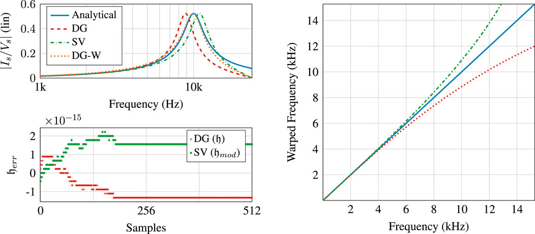
Figure 2. Top: admittance response of RLC PHS discretized with the discrete gradient (DG), discrete gradient with prewarping (DG-W), and Störmer-Verlet (SV) methods with a sampling rate of 48 kHz. The simulations are compared to the analytical response. Bottom: accumulated energy error for the DG scheme and SV scheme over the first 512 samples. Both display errors within machine precision, however, only the DG scheme conserves energy exactly. Right: Comparison of frequency warping of
The discrete gradient method is applied as described in Section 3. The discrete gradient RLC scheme is given by the following equations
The scheme is unconditionally stable by definition of the discrete gradient method. We have the variation in discrete energy,
with the discrete energies being an exact discretization of the continuous-time quantities,
For analyzing numerical dispersion, it is sufficient to analyze the unforced state-update equation, which leads to the characteristic equation
This can be compared to the analytical characteristic equation with
to evaluate the numerical dispersion of the scheme. For the RLC system, it is possible to adapt the parameters
Figure 2 displays the response with and without prewarping. The discrete system response will deviate from the analytical response as
The Störmer-Verlet method produces the following RLC scheme
The scheme is conditionally stable, but not explicit. The exact discrete energy is not preserved and instead a modified energy is preserved:
Here,
and
The energetic quantities have been derived by taking the product of
For the discrete energy to remain positive
The RLC PHS was discretized with the discrete gradient method, with and without prewarping, and the Störmer-Verlet method. Results are shown in Figure 2. The system parameters are
The reed excitation mechanism acts as a blown closed pressure-controlled valve at the inlet of the woodwind bore (Fletcher, 1993). The reed model is nonlinear, an essential trait that produces steady oscillations from a continuous excitation (Chaigne and Kergomard, 2016). We will present a simple single-degree-of-freedom lumped model of the reed, a classical approach found in Backus (1963); Scavone (1997); van Walstijn and Avanzini (2007), among many others. The single reed has been modeled as a cantilever bar by Avanzini and van Walstijn (2004) and as a two-dimensional thin plate in Chatziioannou (2010). However, with a mind towards limiting computational complexity, only a lumped model is considered here.
A model of the single-reed consists of two nonlinear interactions: the reed contact with the lay called “beating”, a characteristic of single-reed instruments, and the nonlinear Bernoulli flow through the reed channel (Chaigne and Kergomard, 2016). We model the beating effect using the Hunt-Crossley impact model, previously utilized in Chatziioannou and van Walstijn (2012), and extend recent work on energy quadratization methods in musical acoustics (Bilbao et al., 2015b; Ducceschi et al., 2021; van Walstijn et al., 2024b) to develop a linearly implicit scheme. The system is modeled using the PHS framework. The PHS approach—not including contact dynamics, but including a turbulence model and 2D flow–was applied to modeling the lip-reed in brass instruments (Lopes and Hélie, 2016). In this section, we will first discuss the governing equations in the lumped reed model and then present a complete PHS description of the system. We will then derive discrete nonlinear and linear implicit schemes based on the discrete gradient method. Coupling the reed model to the bore model will be discussed later on in Section 8.
A lumped reed model aims to capture the behavior at the tip of the reed. We model the reed as a mass-spring-damper system which is a mechanical analogy of the RLC circuit presented in Section 4. The system is based on the position
with

Figure 3. Left: Diagram of the single reed and mouthpiece. Right: A lumped model of the reed including the Hunt-Crossley contact force.
The Hunt-Crossley model can be interpreted as a parallel combination of a nonlinear spring and damper that resists the incursion of one object into another.
A second nonlinearity within the reed model is the flow through the reed channel. We assume a steady, simple, and quasi-stationary Bernoulli flow model (Chaigne and Kergomard, 2016; Sec. 10.3.1.1)
that considers the contribution of reed motion to the flow. It was observed in Lopes and Hélie (2016) that the inclusion of a pumping flow is necessary for the model to be physically realistic and energy conserving. We now present a complete PHS description of the reed system based on Equations 52, 53, 56, 57, and denote momentum
It is worth noting that the flow out of the reed model
and identifying
The dissipation due to the Bernoulli flow is guaranteed to be non-negative by
the system in Equations 58a, 58b maintains an energy balance as all the dissipative terms and
We discretize the system in Equations 58a, 58b using the discrete gradient method and obtain Equation 64 by approximation of the time derivative and gradients. This results in a pair of implicit nonlinear equations in both the state-update equation (due to the Hunt-Crossley force) and the output equation (due to the Bernoulli flow). We will focus on the state-update equation and the discretization of the output equation will be left to Section 8. We are particularly concerned with the discrete-time transcendental equation:
which corresponds to the discretized form of the first line in Equation 58a. It is helpful here to introduce an intermediary variable:
We apply the property in Equation 13 to replace
and Equation 65 to rewrite the transcendental equation as a function whose root is equal to
with
This equation can be solved using a Newton-Raphson iteration with a guaranteed solution due to the convexity of
The discrete Hamiltonian and dissipated energy terms associated with this scheme are
Explicit and linearly implicit schemes representing Hertzian contact dynamics have been derived using energy quadratization strategies in Ducceschi et al. (2021) and van Walstijn et al. (2024b). Explicit Hunt-Crossley contact dynamics were recently presented in van Walstijn et al. (2024a). Energy quadratization has also been used in the discretization of nonlinear port-Hamiltonian systems (Lopes et al., 2015). Invariant energy quadratization (IEQ) (Zhao et al., 2016) and scalar auxiliary variable (SAV) methods (Shen et al., 2018) apply a change of basis to the energy function by representing the energy with a quadratic variable. For single-variable problems, as treated here, the methods are equivalent. We will only quadratize the contact potential, leaving the other energies untouched. The contact potential is now defined based on an auxiliary state
and
where
Applying Equation 73 to the PHS in Equations 58a, 58b we derive a new PHS with elements
and efforts and flows,
The total stored energy in the system is now
Following Ducceschi et al. (2021), we discretize the system by placing
where
and
As discussed by Ducceschi et al. (2021) and van Walstijn et al. (2024b) the value of
Following van Walstijn et al. (2024b), a third branch would be given by determining under what conditions, in Equation 78,
The discrete variation in energy associated with the linearly implicit scheme is derived using the properties of Equations 12, 15
with
In Figure 4, we compare the hysteretic compressive behavior associated with the Hunt-Crossley contact force for the nonlinear and linearly implicit schemes with different initial velocities. As can be seen, the linearly implicit scheme follows the behavior of the nonlinear implicit scheme but does not match it exactly due to how the energy quadratized PHS is discretized. The accuracy decreases with increasing velocity.
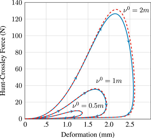
Figure 4. Hunt-Crossley force versus deformation simulated for different initial velocities 0.5, 1, and 2 m/s using the nonlinear implicit scheme (blue) and the linearly implicit scheme (red, dashed). Parameters used for the plot are
The woodwind bore can be modeled in one-dimension as a pipe with a varying cross-sectional area. Viscothermal losses are incorporated according to the model of Zwikker and Kosten (1949). We represent these losses in our model using the network synthesis method proposed in Bilbao et al. (2015a). A PHS formulation of the Webster-Lokshin model which approximates viscothermal losses with various simplifications was proposed in Gorrec and Matignon (2013). We will summarize the frequency domain description of the lossy horn equation, then present a PHS representation of a network synthesis approximation of the viscothermal losses and the overall system. To reduce frequency warping, we will discretize the system with the Störmer-Verlet method. In the absence of losses, the resulting scheme is exactly the scheme presented in Bilbao and Harrison (2016) though derived from a different perspective.
We consider a tube of varying circular cross-sectional area of length
Here,
producing the equivalent system
with
where
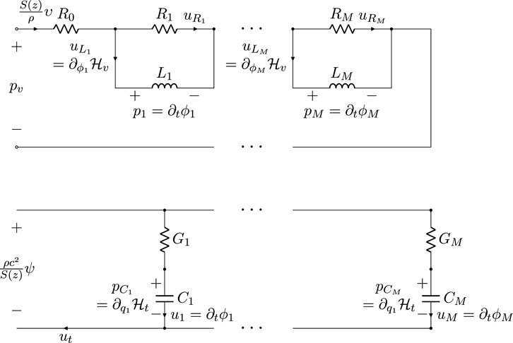
Figure 5.
with fluxes
The losses due to thermal effects,
with charges
Both systems are defined as conjugate PHS systems as the output of both systems are the sum of the flows of their respective storage components. As described in Section 3.2, discretization with the discrete gradient method results in a linearly implicit scheme.
Following Bilbao and Harrison (2016), a power balance of the horn model, including the loss approximations, is derived by taking the product
We can identify the quantities
with
The total system can be written as an infinite dimensional PHS based on the variational derivatives:
The variational derivatives are equivalent to the derivatives of the energy density when the energy density does not depend on the derivatives of the state (Duindam et al., 2009). Here, we use Leibniz’s notation in conjunction with the operator
The distributed PHS formulation of the horn equation with viscothermal losses is then:
The upper left quadrant in
In light of the frequency warping associated with the discrete gradient method we now discretize the system in Equation 96 in time and space with the Störmer-Verlet method. This produces a scheme that, excluding viscothermal losses, is equivalent to the scheme proposed in Bilbao and Harrison (2016). Spatial discretization with the Störmer-Verlet scheme maintains the skew-symmetry property of the upper left block matrix in Equation 96. However, this property combined with the reduced time discretization error does completely characterize the accuracy of the scheme. Analysis of the scheme accuracy in relation to the symplectic property of the discretization method merits further investigation.
The fully discretized horn equation scheme is
Importantly, we define
This equivalence can also be derived by substituting the property
with
We write the scheme in Equations 97a, 97b in vector form by defining two
Viscous and thermal losses are included by means of the explicit update matricies of Equations 99a, 99b, Equations 100a, 100b. The concatenated
where the matrices at each spatial location correspond to the matrices
with
After computing Equations 103a, 103b, the internal viscothermal loss states
where—similar to
The scheme in Equation 103b is driven by an external volume velocity at the input end,
The pressure at the output end depends on the boundary condition at the end of the bore. This is discussed in Section 6.5 where we couple the bore to an unflanged radiation condition and in Section 7 where we couple segments of bores together through two-port elements.
Assuming that the matrix inverses are computed and applied beforehand, the lossy horn equation in Equations 103a, 103b, 103c, 103d has a computational cost of four
Aside from the characterization of losses as a PHS, the scheme described here is exactly the same as the scheme in Bilbao and Harrison (2016). The PHS loss subsystems can be rewritten in a manner that is symbolically equivalent to the losses in Bilbao and Harrison (2016) even though, numerically, the scheme proposed here and the scheme in Bilbao and Harrison (2016) are not equivalent. The discrete energetic quantities follow from the proof given in that article. As such, we do not repeat the proof here. The horn equation scheme is conditionally stable and is determined by the Courant-Friedrichs-Lewy (CFL) condition
with
where
with
and the discrete power transferred through the boundaries is,
Due to discretization with the Störmer-Verlet method, the discrete stored energy and dissipated energy is not an exact sampling of the continuous energy function. Quantities denoted with the subscript
We use the second-order circuit model, shown in Figure 6, presented by Bilbao and Chick (2013) to model the radiation from an unflanged end of the bore. The model is described by the following PHS
with parameters
where
and the dissipated energy and boundary power are
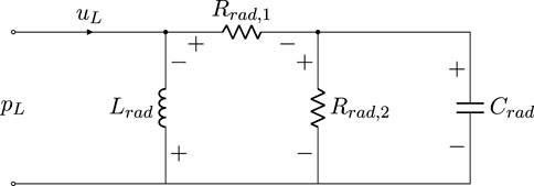
Figure 6. Circuit approximation of the radiation from an unflanged end of a circular bore after Bilbao and Chick (2013)
We discretize this system with the discrete gradient method on the
The discrete energy balance is maintained by the exact discretized forms of the quantities in Equations 111, 112. We will discuss coupling the radiation to the bore in Section 8.
The woodwind tonehole is normally represented by a frequency-domain equivalent circuit model involving four elements: two series inertances equal to
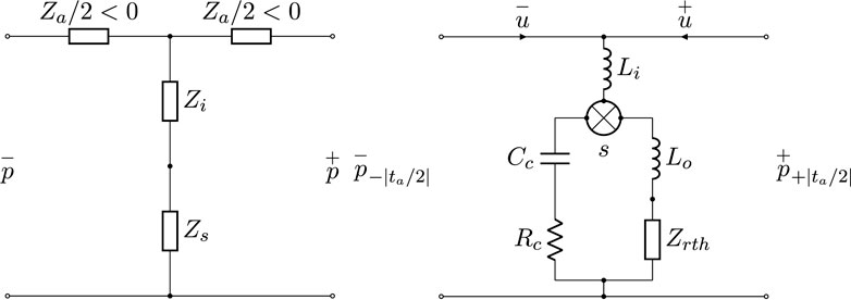
Figure 7. Left: Equivalent circuit model of the tonehole with negative series inertances
For a tonehole with tonehole radius
which has different values when the tonehole is open and closed corresponding to the length correction values
with
and the inner length correction is
The closed tonehole impedance includes the same matching volume and inner length correction terms as appear in the open tonehole impedance. The form of the closed tonehole impedance is different due to the closed end condition and, correspondingly, the radiation length correction is omitted,
In both models, viscothermal losses can be incorporated by replacing the imaginary wavenumber
where the related loss immitances are evaluated with the tonehole radius
A known hindrance in developing a time-domain model based on the lumped tonehole approximation is that the series length correction,
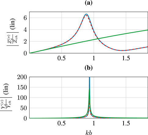
Figure 8. Comparison of the normalized open tonehole shunt impedance (A) and closed tonehole shunt admittance (B) for the lossless (red, dashed), lossy (blue, solid) tonehole models in Lefebvre and Scavone (2012), and the circuit approximation (green, solid) proposed in this article. Parameters used for the plots are
Following the approach in van Walstijn and Scavone (2000), we develop a discrete-time model of the closed and open shunt impedances via a low-frequency approximation. To model the open shunt impedance, we use the frequency independent
For the closed tonehole, the small angle approximation of
In the absence of these components, the closed tonehole model in Equation 118 behaves akin to a Helmholtz resonator and will produce a strong resonance at a frequency proportional to the volume of the closed tonehole (Chaigne and Kergomard, 2016, 1.5). One effect of the viscothermal losses (Equation 119) and the frequency dependent inner length correction (Equations 117a, 117b, 117c) is to dramatically dampen the tonehole resonance. A secondary effect is a shifting down—in frequency—of the same resonance. In both cases, the frequency dependent length correction is the more dominant effect. The additional resistance,
Both parameters can also be used to compensate for the effects of frequency warping. When the tonehole model is eventually discretized, the theoretical closed tonehole resonance can potentially be at a frequency near or above the Nyquist limit. To minimize the effects of frequency warping,
To transition between the closed and open tonehole models, van Walstijn and Scavone (2000) proposed placing the shunt compliance and inertance, corresponding to the closed and open tonehole models, in parallel. The compliance and inertances values are then modified as a function of a variable between zero and one. The overall effect is to open the circuit on the opposing parallel branch by setting the compliance to zero when the tonehole is open or the inertance to infinity when the tonehole is closed. An immediate issue with this approach, outside of simulating a system with infinite inertance at times, is that the energy stored in the tonehole system becomes infinite when the tonehole is opened.
In light of these issues, we instead model the tonehole transition using a switching PHS which is used to represent systems with variable topology (Duindam et al., 2009, 2.2.5). As a result, the energy stored in the tonehole is independent of the tonehole state. The switch does not have to be instantaneous and half-holing is still possible using the switching model. We combine the open and closed tonehole systems using the switching variable
with
The overset symbols
The energy dissipated in the system is now also a function of
and the power transmitted through the two-port boundary is
The model is a PHS for the tonehole state value
The system in Equations 121a, 121b has a hybrid PHS definition that is not easily discretized using the methods outlined in Section 3.2. However, using the definition in Equation 13 we can rewrite Equation 121a as
where
The explicit update for the tonehole system is
and defined by the matrices
where
In Figure 9, we examine the input impedance of a cylindrical pipe with a single tonehole at its center for different values of
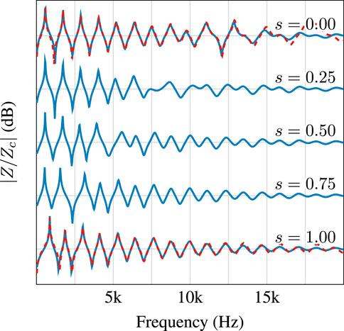
Figure 9. Input impedances of a cylindrical tube and single tonehole derived from a discrete PHS simulation (blue) for various tonehole conditions
To build a complete model we must connect the bore, tonehole, radiation, and reed sub-models discussed thus far. The pressure and volume velocities at the external ports in these elements have been defined such that they are linked by the
We first consider a general two-port system coupling two bores discretized with the scheme in Equations 97a, 97b. We seek to solve the equation,
for
Using Equations 98a, 98b, 13, we rewrite
This equation can be solved for the vector
and
The overset symbols have again been used to distinguish elements
To couple the bore to the one-port lumped radiation model described Section 6.5 we only need to solve the top line of Equation 131 and the matrix
The final remaining step is to couple the reed model from Section 5 to the lossy horn equation at
corresponding to the bottom line of Equation 130. The discrete-time definitions for the jet-area
The associated discrete energy loss due to the Bernoulli flow and power transfer through the boundary are
Using the definition of
where
Replacing
As in Bilbao et al. (2015b), we have a pair of coupled nonlinear equations,
For the linearly implicit quadratized scheme discussed in Section 5.3, we can derive a direct solution for
with coefficients dependent on the branching conditions of
with
and taking the positive solution to the quadratic equation:
The value of
For our simulation experiment, we designed a simplified bore profile with two toneholes. Through an optimization procedure similar to Lefebvre (2010), the bore length and tonehole position were tuned such that the first impedance peak corresponds to the note C4 when all the holes are closed, and D4 and E4 when one tonehole is open and the other is closed. The resulting bore profile and tonehole positions are shown in Figure 10, and the dots indicate the tonehole positions. The bore radius is defined by the piecewise function
and is composed of a cylinder, truncated cone, and Bessel horn (Chaigne and Kergomard, 2016). The parameters
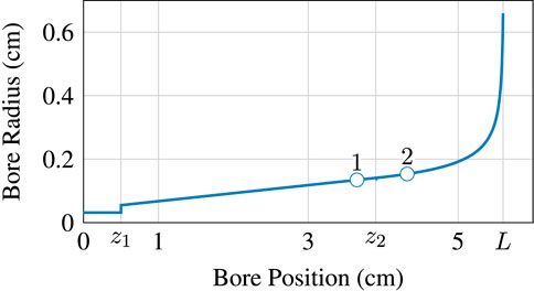
Figure 10. Simplified bore profile used in final simulation consisting of a cylinder, truncated cone, and a Bessel horn with two toneholes. Tonehole positions are indicated by white markers. Parameter values are provided in Table 1.
The discrete Hamiltonian of the system is the sum of the discrete Hamiltonian from each sub-model
Likewise, the dissipated energy is,
The only boundary term is
as the boundary terms for each sub-model cancel with each other due to the use of energy-conserving interconnections.
The simplified geometry was used to synthesize the first two measures of “Mary Had a Little Lamb,” corresponding to a 4.8 s long audio sample1. We evaluate the pressure at
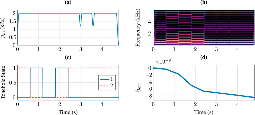
Figure 11. Simulation synthesizing the first two measures of “Mary Had a Little Lamb” using the simplified bore described in this section. (A) and (C) display the provided mouth pressure and tonehole states used in the synthesis. (B) and (D) Demonstrate a spectrogram of the resulting synthesized audio and the accumulated energy error.
Simulations were run in Python on an Apple M3 CPU at a 48 kHz sample rate and are not intended for real-time computations. Defining the real-time factor (RTF) as the ratio of the simulated elapsed time and the real processing elapsed time, the simulation performed in this section had an RTF approximately equal to 1/16. An RTF much greater than unity is necessary for real-time computations. A significant bottleneck in the simulation is computation of the viscothermal losses. Running the same simulation without viscothermal losses resulted in an RTF of approximately 1/5.
In this article, we have presented a port-Hamiltonian system model of a single-reed woodwind instrument comprised of a lumped reed model, a one-dimensional horn model, and a lumped tonehole model. We then discretized each model using FDTD methods. The PHS framework has aided us in systematically deriving sub-models that can be composed in a modular and energy-conserving fashion, allowing us to construct bores with arbitrary geometries and tonehole placements.
A final simulation based on a simplified bore geometry demonstrates bitwise machine precision variations in the accumulated energy error resulting in a slow long term drift. The drift is not systematic, but random and is based on the propagation of random finite-precision rounding errors. However, further statistical analysis of the scheme should be conducted from hundreds of runs to characterize the behavior of the error as in Hairer et al. (2008). Real-time computation was not a concern in our implementation and proper benchmarking in a compiled programming language, such as C++, would allow for the evaluation of the computational load of the scheme.
Refinements to the lumped reed model and tonehole model were presented. A linearly implicit scheme based on energy quadratization of the Hunt-Crossley contact force was proposed and the behavior of the scheme was compared to a nonlinear implicit scheme solved via a Newton-Raphson iteration. We demonstrated that the linearly implicit scheme maintains the overall characteristic of the interaction. A new low-frequency lumped model of the tonehole was proposed that provides better agreement to existing literature by including damping in the closed tonehole model. The stored energy in the discrete tonehole model is now bounded through use of a switching PHS structure.
The lossy horn equation was discretized using a general Störmer-Verlet scheme, motivating the scheme proposed by Bilbao and Harrison (2016). This initial investigation merits further research into the efficacy of symplectic schemes for discretizing musical systems where numerical dispersion is of a primary concern. A major computational bottleneck in the overall model is due to the complexity of the viscothermal losses as two 16th-order filters are necessary at every spatial index to accurately model the losses (Bilbao et al., 2015a). Development of a more efficient representation remains for future work. Due again to the modular nature of the PHS framework, any future improvements to the sub-models described here or new models of radiation conditions or losses—provided these sub-models are described as a PHS—can be incorporated into the existing model with ease.
The original contributions presented in the study are included in the article/Supplementary Material, further inquiries can be directed to the corresponding author.
CD: Conceptualization, Data curation, Formal Analysis, Funding acquisition, Investigation, Methodology, Writing–original draft, Writing–review and editing. GS: Funding acquisition, Writing–review and editing.
The author(s) declare that financial support was received for the research, authorship, and/or publication of this article. This research was supported by the Vanier Canada Graduate Scholarships program.
The authors would like to thank Vasileios Chatziioannou for helpful discussions on symplectic schemes and Mark Rau for discussions regarding the horn equation.
The authors declare that the research was conducted in the absence of any commercial or financial relationships that could be construed as a potential conflict of interest.
The authors declare that no Generative AI was used in the creation of this manuscript.
All claims expressed in this article are solely those of the authors and do not necessarily represent those of their affiliated organizations, or those of the publisher, the editors and the reviewers. Any product that may be evaluated in this article, or claim that may be made by its manufacturer, is not guaranteed or endorsed by the publisher.
The Supplementary Material for this article can be found online at: https://www.frontiersin.org/articles/10.3389/frsip.2025.1519450/full#supplementary-material.
1An audio sample is provided as part of the supplementary material.
Avanzini, F., and van Walstijn, M. (2004). Modeling the mechanical response of the reed-mouthpiece-lip system of a clarinet. part i. a one-dimensional distributed model. Acta Acustica united Acustica 90, 537–547.
Backus, J. (1963). Small-vibration theory of the clarinet. J. Acoust. Soc. Am. 35, 305–313. doi:10.1121/1.1918458
Berners, D. P. (1999). Acoustic and signal procesing Techniques for physical Modeling of brass instruments. Ph.D. Thesis. Stanford University.
Bilbao, S. (2008). “Direct simulation for reed wind instruments,” in 11th International Conference on digital audio effects (DAFx-08). Espoo, Finland.
Bilbao, S., and Chick, J. (2013). Finite difference time domain simulation for the brass instrument bore. J. Acoust. Soc. Am. 134, 3860–3871. doi:10.1121/1.4822479
Bilbao, S., and Harrison, R. (2016). Passive time-domain numerical models of viscothermal wave propagation in acoustic tubes of variable cross section. J. Acoust. Soc. Am. 140, 728–740. doi:10.1121/1.4959025
Bilbao, S., Harrison, R., Kergomard, J., Lombard, B., and Vergez, C. (2015a). Passive models of viscothermal wave propagation in acoustic tubes. J. Acoust. Soc. Am. 138, 555–558. doi:10.1121/1.4926407
Bilbao, S., Torin, A., and Chatziioannou, V. (2015b). Numerical modeling of collisions in musical instruments. Acta Acustica United Acustica, 101.
Caussé, R., Kergomard, J., and Lurton, X. (1984). Input impedance of brass musical instruments—comparison between experiment and numerical models. J. Acoust. Soc. Am. 75, 241–254. doi:10.1121/1.390402
Chaigne, A., and Kergomard, J. (2016). Acoustics of musical instruments. New York, NY: Springer-Verlag.
Chatziioannou, V. (2010). Forward and inverse modelling of single-reed woodwind instruments with application to digital sound synthesis. Belfast, Northern Ireland: Queen’s University Belfast. Ph.D. thesis.
Chatziioannou, V. (2019). Structure preserving algorithms for simulation of linearly damped acoustic systems. J. Numer. Analysis, Industrial, Appl. Math. (JNAIAM) 13.
Chatziioannou, V., Schmutzhard, S., Pàmies-Vilà, M., and Hofmann, A. (2019). Investigating clarinet articulation using a physical model and an artificial blowing machine. Acta Acustica united Acustica 105, 682–694. doi:10.3813/aaa.919348
Chatziioannou, V., and van Walstijn, M. (2012). Estimation of clarinet reed parameters by inverse modelling. Acta acustica united Acustica 98, 629–639. doi:10.3813/aaa.918543
Dalmont, J.-P., Nederveen, C. J., Dubos, V., Ollivier, S., Méserette, V., and te Sligte, E. (2002). Experimental determination of the equivalent circuit of an open side hole: linear and nonlinear behaviour. Acta Acustica united Acustica 88, 567–575.
Dubos, V., Kergomard, J., Khettabi, A., Dalmont, J.-P., Keefe, D. H., and Nederveen, C. (1999). Theory of sound propagation in a duct with a branched modal decomposition. Acustica united Acta Acoust. 85, 153–169.
Ducceschi, M., Bilbao, S., Willemsen, S., and Serafin, S. (2021). Linearly-implicit schemes for collisions in musical acoustics based on energy quadratisation. J. Acoust. Soc. Am. 149, 3502–3516. doi:10.1121/10.0005008
V. Duindam, A. Macchelli, S. Stramigioli, and H. Bruyninckx (2009). Modeling and control of complex physical systems: the port-Hamiltonian approach (Springer-Verlag).
Falaize, A., and Hélie, T. (2016a). Passive guaranteed simulation of analog audio circuits: a port-Hamiltonian approach. Appl. Sci. 273. doi:10.3390/app6100273
Falaize, A., and Hélie, T. (2017b). Passive simulation of the nonlinear port-Hamiltonian modeling of a rhodes piano. J. Sound Vib. 390, 289–309. doi:10.1016/j.jsv.2016.11.008
Fletcher, N. H. (1993). Autonomous vibration of simple pressure-controlled valves in gas flows. J. Acoust. Soc. Am. 93, 2172–2180. doi:10.1121/1.406857
Gorrec, Y. L., and Matignon, D. (2013). Coupling between hyperbolic and diffusive systems: a port-Hamiltonian formulation. Eur. J. Control 19, 505–512. doi:10.1016/j.ejcon.2013.09.003
Hairer, E., Lubich, C., and Wanner, G. (2000). Geometric Numerical Integration: structure-preserving algorithms for ordinary different equations. Springer.
Hairer, E., Lubich, C., and Wanner, G. (2003). Geometric numerical integration illustrated by the Störmer–Verlet method. Acta Numer. 12, 399–450. doi:10.1017/s0962492902000144
Hairer, E., McLachlan, R. I., and Razakrivony, A. (2008). Achieving brouwer’s law with implicit runge-kutta methods. BIT Numer. Math. 48, 231–243. doi:10.1007/s10543-008-0170-3
Harrison-Harsley, R. (2018). Physical modelling of brass instruments using finite-difference time-domain methods. Edinburgh, UK: University of Edinburgh. Ph.D. thesis.
Hélie, T. (2022). “Elementary tools on Port-Hamiltonian Systems with applications to audio/acoustics,” in 2nd spring School on Theory and Applications of port-Hamiltonian systems (Frauenchiemsee, Germany).
Hélie, T., and Roze, D. (2016). “Corde non linéaire amortie: fomulation Hamiltonienne à ports, réduction d’ordre exacte et simulation à passivité garantie,” in 13ème Congrès Français d’Acoustique. Le Mans, France.
Keefe, D. H. (1982). Theory of the single woodwind tone hole. J. Acoust. Soc. Am. 72, 676–687. doi:10.1121/1.388248
Keefe, D. H. (1984). Acoustical wave propagation in cylindrical ducts: Transmission line parameter approximations for isothermal and nonisothermal boundary conditions. J. Acoust. Soc. Am. 75, 58–62. doi:10.1121/1.390300
Lefebvre, A. (2010). Computational acoustic methods for the design of woodwind instruments. Montréal, Canada: McGill University. Ph.D. thesis.
Lefebvre, A., and Scavone, G. P. (2012). Characterization of woodwind instrument toneholes with the finite element method. J. Acoust. Soc. Am. 131, 3153–3163. doi:10.1121/1.3685481
Lopes, N. (2016). Approche passive pour la modeélisation, la simulation et l’étude d’un banc de test robotisé pour les instruments de type cuivre. Ph.D. thesis, Université Paris 6 (UPMC)
Lopes, N., and Hélie, T. (2016). Energy balanced model of a jet interacting with a brass player’s lip. Acta Acoust. united Acustica 102, 141–154. doi:10.3813/aaa.918931
Lopes, N., Hélie, T., and Falaize, A. (2015). “Explicit second-order accurate method for the passive guaranteed simulation of port-Hamiltonian systems,” in International Federation of Automatic control (IFAC).
Maschke, B. M., and van der Schaft, A. J. (1993). “Port-controlled Hamiltonian systems: modelling origins and systemtheoretic properties,” in Nonlinear control systems design 1992 (Elsevier), 359–365.
McIntyre, M., Schumacher, R., and Woodhouse, J. (1983). On the oscillations of musical instruments. J. Acoust. Soc. Am. 74, 1325–1345. doi:10.1121/1.390157
Mignot, R., Hélie, T., and Matignon, D. (2008). “Stable relization of a delay system modeling a convergent acoustic cone,” in 16th Mediterranean Conference on Control and Automation. Ajaccio, France.
Mignot, R., Hélie, T., and Matignon, D. (2010). Digital waveguide modeling for wind instruments: Building a state–space representation based on the Webster–Lokshin model. IEEE Trans. Audio, Speech, Lang. Process. 18, 843–854. doi:10.1109/tasl.2009.2038671
Müller, R. (2021). Time-continuous power-balanced simulation of nonlinear audio circuits: realtime processing framework and aliasing rejection. Sorbonne Université: Ph.D. thesis.
Müller, R., and Hélie, T. (2021). “Fully-implicit algebro-differential parameterization of circuits,” in Proceedings of the 23rdInternational Conference on digital audio effect (DAFx2020).
Scavone, G. (1997). An acoustic analysis of single-reed woodwind instruments with an Emphasis on design and performance issues and digital waveguide modeling techniques. Stanford, CA: Stanford University. Ph.D. thesis.
Scavone, G., and Cook, P. (1998). “Real-time computer modeling of woodwind instruments,” in 1998 International Symposium on musical acoustics Leavenworth, WA.
Scavone, G. P. (2024). “An open-source project for wind instrument modeling using digital waveguides,” in 186thMeeting of the acoustical Society of America.
Shen, J., Xu, J., and Yang, J. (2018). The scalar auxiliary variable (SAV) approach for gradient flows. J. Comput. Phys. 353, 407–416. doi:10.1016/j.jcp.2017.10.021
Smith, J. O. (1986). “Efficient simulation of the reed-bore and bow-string mechanisms,” in Proceedings of the 12th International Conference on music computing (Netherlands: Den Haag) Available at: http://books.w3k.org/
Smith, J. O. (1992). Physical modeling using digital waveguides. Comput. Music J. 16, 74–91. doi:10.2307/3680470
Torin, A. (2015). Percussion instrument modelling in 3D: sound synthesis through time domain numerical simulation. Edinburgh, UK: University of Edinburgh. Ph.D. thesis.
Välimäki, V. (1995). Discrete-time modeling of acoustic tubes using fractional delay filters. Helsinki, Finland: Helsinki University of Technology. Ph.D. thesis.
van der Schaft, A. (2006). “Port-Hamiltonian systems: an introductory survey,” in Proceedings of the International Congress of Mathematicians. Madrid, Spain.
van der Schaft, A., and Jeltsema, D. (2014). Port-Hamiltonian systems theory: an introductory Overview. Hamilt. Syst. Theory Introd. Overv. 1, 173–378. doi:10.1561/2600000002
van Walstijn, M., and Avanzini, F. (2007). Modelling the mechanical response of the reed-mouthpiece-lip system of a clarinet. part ii: a lumped model approximation. Acta Acustica united Acustica 93, 435–446.
van Walstijn, M., Bridges, J., and Mehes, S. (2016). “A real-time synthesis oriented tanpura model,” in Proceedings of the 19thInternational Conference on digital audio effects (DAFx-16).
van Walstijn, M., and Campbell, M. (2003). Discrete-time modeling of woodwind instrument bores using wave variables. J. Acoust. Soc. Am. 113, 575–585. doi:10.1121/1.1515776
van Walstijn, M., Chatziioannou, V., and Athanasopoulos, N. (2024a). An explicit scheme for energy-stable simulation of mass-barrier collisions with contact damping and dry friction. IFAC-PapersOnLine 58, 214–219. doi:10.1016/j.ifacol.2024.08.283
van Walstijn, M., Chatziioannou, V., and Bhanuprakash, A. (2024b). Implicit and explicit schemes for energy-stable simulation of string vibrations with collisions: Refinement, analysis and comparison. J. Sound Vib. 569, 117968. doi:10.1016/j.jsv.2023.117968
van Walstijn, M., and Scavone, G. (2000). “The wave digital tonehole model,” in 2000 International computer music Conference Berlin, Germany.
Wendlandt, J. M., and Marsden, J. E. (1997). Mechanical integrators derived from a discrete variational principle. Phys. D. 106, 223–246. doi:10.1016/s0167-2789(97)00051-1
Wetzel, V., Hélie, T., and Silve, F. (2019). “Power balanced time-varying lumped parameter model of a vocal tract: modeling and simulation,” in 26th International Conference on sound and Vibration.
Willemsen, S. (2021). The Emulated ensemble: real-time simulation of musical instruments using finite-difference time-domain methods. Aalborg, Denmark: Aalborg University. Ph.D. thesis.
Yalçin, Y., Sümer, L. G., and Kurtulan, S. (2015). Discrete-time modeling of Hamiltonian systems. Turkish J. Electr. Eng. Comput. Sci. 23, 149–170. doi:10.3906/elk-1212-23
Yang, X. (2016). Linear, first and second-order, unconditionally energy stable numerical schemes for the phase field model of homopolymer blends. J. Comput. Phys. 327, 294–316. doi:10.1016/j.jcp.2016.09.029
Zhao, J., Want, Q., and Yang, X. (2016). Numerical approximations for a phase field dendritic crystal growth model based on the invariant energy quadratization approach. Int. J. Numer. Methods Eng. 110, 279–300. doi:10.1002/nme.5372
Keywords: wind instrument, energy-stable schemes, linearly implicit schemes, multi-physics modeling, energy quadratization
Citation: Darabundit CC and Scavone G (2025) Discrete port-Hamiltonian system model of a single-reed woodwind instrument. Front. Signal Process. 5:1519450. doi: 10.3389/frsip.2025.1519450
Received: 29 October 2024; Accepted: 29 January 2025;
Published: 27 March 2025.
Edited by:
Thomas Hélie, UMR9912 Sciences et Technologies de la Musique et du Son (STMS), FranceReviewed by:
David Roze, UMR9912 Sciences et Technologies de la Musique et du Son (STMS), FranceCopyright © 2025 Darabundit and Scavone. This is an open-access article distributed under the terms of the Creative Commons Attribution License (CC BY). The use, distribution or reproduction in other forums is permitted, provided the original author(s) and the copyright owner(s) are credited and that the original publication in this journal is cited, in accordance with accepted academic practice. No use, distribution or reproduction is permitted which does not comply with these terms.
*Correspondence: Champ C. Darabundit, Y2hhbXAuZGFyYWJ1bmRpdEBtYWlsLm1jZ2lsbC5lZHU=
Disclaimer: All claims expressed in this article are solely those of the authors and do not necessarily represent those of their affiliated organizations, or those of the publisher, the editors and the reviewers. Any product that may be evaluated in this article or claim that may be made by its manufacturer is not guaranteed or endorsed by the publisher.
Research integrity at Frontiers

Learn more about the work of our research integrity team to safeguard the quality of each article we publish.