 Christopher Remde
 Igor M. Sauer
 Moritz Queisner
- 1Charité – Universitätsmedizin Berlin, Corporate Member of Freie Universität Berlin and Humboldt-Universität zu Berlin, Department of Surgery, Campus Charité Mitte, Campus Virchow-Klinikum, Berlin, Germany
- 2Humboldt Universität zu Berlin, Cluster of Excellence Matters of Activity, Berlin, Germany
Introduction: Volumetric video production in commercial studios is predominantly produced using a multi-view stereo process that relies on a high two-digit number of cameras to capture a scene. Due to the hardware requirements and associated processing costs, this workflow is resource-intensive and expensive, making it unattainable for creators and researchers with smaller budgets. Low-cost volumetric video systems using RGBD cameras offer an affordable alternative. As these small, mobile systems are a relatively new technology, the available software applications vary in terms of workflow and image quality. In this paper we provide an overview of the technical capabilities of sparse camera volumetric video capture applications and assess their visual fidelity and workflow.
Materials and methods: We selected volumetric video applications that are publicly available, support capture with multiple Microsoft Azure Kinect cameras and run on consumer-grade computer hardware. We compared the features, usability, and workflow of each application and benchmarked them in five different scenarios. Based on the benchmark footage, we analyzed spatial calibration accuracy, artifact occurrence and conducted a subjective perception study with 19 participants from a game design study program to assess the visual fidelity of the captures.
Results: We evaluated three applications, Depthkit Studio, LiveScan3D and VolumetricCapture. We found Depthkit Studio to provide the best experience for novel users, while LiveScan3D and VolumetricCapture require advanced technical knowledge to be operated. The footage captured by Depthkit Studio showed the least amount of artifacts by a larger margin, followed by LiveScan3D and VolumetricCapture. These findings were confirmed by the participants who preferred Depthkit Studio over LiveScan3D and VolumetricCapture.
Discussion: Based on the results, we recommend Depthkit Studio for the highest fidelity captures. LiveScan3D produces footage of only acceptable fidelity but is the only candidate that is available as open-source software. We therefore recommend it as a platform for research and experimentation. Due to the lower fidelity and high setup complexity, we recommend VolumetricCapture only for specific use-cases where its ability to handle a high number of sensors in a large capture volume is required.
1 Introduction
Most videos today are produced and consumed in a traditional format, where a camera sensor captures a 2D projection of a scene from a fixed perspective. This method lacks spatial depth and confines viewers to a predetermined viewpoint. While this is sufficient for many applications, certain use-cases benefit from a capture method that includes spatial information and allows observers to freely change their perspective (Alain et al., 2023). For example, instructional volumetric videos for spatially complex processes, such as machine operation, garment construction or even surgical procedures would be able to depict these workflows in their full spectrum. More immersive tele-conferencing systems and virtual site visits could reduce emission associated with traveling, and photorealistic animated assets for media production could be created with low expenditure. While volumetric videos today are almost exclusively produced in studios, all these use cases call for mobile, low-cost and adaptable capture systems. 3D scanning of static scenes is already a well-established and mature process, widely adopted across various disciplines. Recent advances in this field, such as Neural Radiance Fields (Barron et al., 2022) or Gaussian Splatting (Kerbl et al., 2023) have significantly enhanced the fidelity of these scans, pushing them towards photorealism. In static scenes, a single camera can be moved around the subject to produce a dataset. In dynamic scenes however, a dense array of cameras is needed to capture all angles of the scene simultaneously. This increases productions costs and limits the production of volumetric video to film studios, research facilities, and large tech companies. To reduce production costs as well as increase accessibility and mobility, methods that require fewer cameras and compute time are essential. Currently, the most common method for capturing volumetric video from sparse viewpoints involves the use of RGBD-cameras. These cameras can capture both the color (RGB) and depth (D) value for each pixel and are available at an affordable consumer price point. Moreover, they are compatible with consumer-grade PC hardware, making them suitable for low-cost setups. The emergence of affordable RGBD-cameras, alongside more widely available presentation devices (i.e., virtual reality head-mounted displays, VR-HMDs) have since created a market niche for low-cost volumetric video capture systems. Several commercial and non-commercial research applications are available. These applications provide access to volumetric video production for more creators, due to their low entry barrier both in terms of technical complexity and costs. The purpose of this paper is to provide an overview of affordable and accessible volumetric video capture applications, especially for first-time users. We highlight the strengths and limitations of each system to help readers make informed decisions based on their specific needs. To facilitate the comparison between these systems and their future iterations, we propose a benchmark for evaluating the visual fidelity of sparse camera volumetric video applications.
Although the RGBD camera based workflow remains the most popular method for creating sparse camera volumetric videos, a variety of other experimental approaches exist. The common goal of all methods is to extract the spatial information of a scene from a given optical input. Existing approaches can be sorted into four categories:
1.1 Depth sensors
Depth sensors physically capture the spatial information of the scene, most often by measuring the time it takes for light to travel from the camera to the scene and back. Popularized by the Xbox Kinect (Microsoft Corporation, 2009), nowadays many affordable RGBD cameras are available from various manufacturers, such as the Realsense D455 (Intel Corporation, 2024), Azure Kinect (Microsoft Corporation, 2020), Femto Mega/Bolt (Orbbec, 2023), or ZED2i (Stereolabs Inc. 2023). These sensors provide scene depth based on physical measurements. However, the resolution of these sensors is still relatively low, with no consumer model exceeding one megapixel, and the measurements can be distorted by reflective, transparent and emissive objects.
1.2 Monocular depth estimation
Monocular depth estimation methods aim to estimate the scene depth using only two-dimensional photographs as input. A neural network is trained on a large dataset of 2D photos paired with a depth map, which can then be used to infer a depth map from unseen photos. While recent models such as ZoeDepth (Bhat et al., 2023), Depth Anything (Yang et al., 2024) and Depth Pro (Bochkovskii et al., 2024) perform well on single images, these models are not yet suitable for dynamic sequences as they lack temporal coherence. As the techniques improve, and models targeted towards video monocular depth estimation with higher temporal coherency may be developed, depth estimation could improve or replace RGBD sensors.
1.3 Sparse photogrammetry
Photogrammetric approaches try to exploit recognizable landmarks in the images, which can be used to infer the spatial relationship between different images and camera poses. This process is also the basis of the SfM process, although classical methods require a large amount of input data. Recent advances in this field have shown to produce usable outputs even from sparse input data (Chibane et al., 2021; Truong et al., 2023). Although the number of input images required has been greatly reduced, a setup of about 10–20 cameras is still needed to cover a captured subject from all angles. Further advances in this area, combined with approaches using very low-cost cameras, such as the Raspberry Pi camera module, may make these setups economically available to amateur creators in the future (Bönsch et al., 2019).
1.4 Foundation models
Foundation models are deep learning networks that have been trained on large datasets in their domain. While these models have been widely used in other applications, such as large language models or image generation, this approach has only recently been applied to scene reconstruction, with the introduction of Dust3r (Wang et al., 2024). Using the learned priors, the model can efficiently fill the data gaps between very sparse input images, allowing full scene reconstruction with as little as two opposing views of the subject. This method has already been applied to dynamic scenes and shows promising results for single-viewpoint videos (Zhang et al., 2024). However, full dynamic scene reconstruction using multiple camera angles has yet to be demonstrated and the high GPU processing requirements could make this method expensive.
1.5 Comparisions
Since RGBD based approaches remain the most popular and widespread technology for capturing sparse camera volumetric video at the time of publication, our paper focuses on this technique. While publications which represent the common techniques and challenges in the field of RGBD camera-based volumetric video applications exist (Jin et al., 2024), to our knowledge, no published work to date has undertaken a comparison of the features, workflow, or visual quality generated with these systems. However, there are several related publications that address segments of this evaluation process: The image quality of RGBD cameras has been well studied (Tölgyessy et al., 2021; Rijal et al., 2023), but the scope of these evaluations focusses on the performance of only a single device and emphasizes specific technical parameters. The work of Zerman et al. (2019) and Zerman et al. (2020) assesses the subjective perception of the effects of compression algorithms and different rendering techniques on volumetric videos. Similarly, Subramanyam et al. (2020) evaluate the impact of different point cloud compression methods but extend the study environment to display the data on virtual reality (VR) HMD instead of conventional two-dimensional displays. The three degrees of freedom (3DOF) study setup used in this paper was the basis of our study environment. Our subjective assessment methods were inspired by the work of Zerman et al. and Subramanyam et al. There is no literature that defines a benchmarking setup for comparing sparse RGBD camera volumetric video applications. We therefore propose a new benchmark, tuned to challenge the unique capabilities of these systems.
2 Materials and methods
2.1 Selection criteria of volumetric video capture software
For the evaluation, we focused on free or commercially, publicly available, volumetric video capture applications. All selected applications need to be able to capture images from multiple RGBD cameras, process the sensor data into a coherent spatial and temporal representation, and export the output into a common and widespread file format. The hardware requirements posed by the applications should be able to be fulfilled with widely available consumer-grade components. Including commercial software into a scientific comparison presents challenges for the reproducibility of the results, as access to these applications may be limited and can become unavailable on the market. However, open-source alternatives currently show a notable gap in fidelity compared to commercial solutions. To more accurately represent the state-of-the-art capabilities available today, we included commercial applications in the comparison. Although this article focuses on low-cost systems, we imposed no specific restrictions on the costs of the software applications. To allow readers to assess the affordability of each application we inform about their associated licensing costs (Table 2).
Variations in image quality across different camera models can significantly impact the quality of the volumetric video produced. Hence, achieving a reliable comparison between different software applications requires the use of an identical camera model across all tests. Among all available options, the Microsoft Azure Kinect was selected due to its universal support across all software applications and its provision of state-of-the-art image quality (Rijal et al., 2023; Tölgyessy et al., 2021). At the time of writing this paper, the production of the Azure Kinect has been discontinued, but the underlying sensor hardware continues to be manufactured as the Orbecc Femto Bolt/Mega (Orbbec 3D Technology International Inc., 2024). These cameras utilize an identical depth sensor and only a slightly modified color sensor compared to the Azure Kinect models. The hardware similarities suggest that the results obtained using the Azure Kinect are transferable to these newer models.
To identify suitable candidates for comparison, we conducted an extensive internet search. Given the relatively novel and niche factor of the volumetric video market, we were unable to find any repositories, articles or reviews, that offered comprehensive lists of potential software applications. To address this issue, we crawled several internet archives using search terms such as “volumetric video,” “depth sensors,” “RGBD” and “4D scanning.” Additionally, commercial software applications were identified by searching company databases such as Crunchbase (Crunchbase Inc., 2024), while non-commercial, research and open-source candidates, were located through open source repositories and scientific databases such as Github (Microsoft Corporation, 2024), ArXiv (Cornell University, 2024) and IEEE Explore (IEEE, 2024). Through this process we identified six candidates which fulfilled our requirements. Listed in no particular order, the candidates are: Depthkit Studio (Scatter, 2024), SOAR (Stream Soar, 2023), EF EVE (Experimental Foundation, 2023), LiveScan3D (Kowalski, Naruniec, Daniluk., 2015), Brekel Point-Cloud v3 (Brekel, 2024) and VolumetricCapture (Sterzentsenko et al., 2018). During the benchmarking phase, the commercial candidates SOAR and EF EVE became permanently unavailable due to restructuring processes in the authoring companies. While we were able to conduct some tests with Brekel Pointcloud v3, a major bug prevented the capture of volumetric videos. All software authors were contacted to confirm that the software, or a bug fix, will not become available in the midterm. Therefore, only the candidates Depthkit Studio, LiveScan3D and VolumetricCapture could be included into the comparison.
2.2 Benchmark
To establish a standardized framework for assessing the volumetric video quality of each software application, we captured footage of five predefined benchmark scenes using three different camera configurations. These scenes were selected to represent varying capture conditions, covering a range of spatial complexities and adaptability requirements. Rigorous control measures were implemented to ensure the consistency of the benchmark environment, mitigating the influence from any variable beyond the software application under evaluation. It is important to note that all software applications presented in this paper are capable of producing higher quality captures than those shown in the benchmarks, when capture setups are optimized to their specific needs. In some cases, limitations within the software required adjustments to the physical benchmarking setup, which were accommodated accordingly.
2.2.1 Hardware
Cost-effective setups have to balance the hardware quantity against its qualitative gains in fidelity. During testing, we found that using four cameras placed at regular intervals around the scene provided sufficient coverage, but some elevated areas could be obstructed. Adding one additional camera above the scene provided more seamless coverage from all viewing angles. Therefore, we decided to use five Microsoft Azure Kinect cameras in all our benchmarks.
Each volumetric capture software poses different requirements on the computing platform used to control, record, and process the captures. The most important difference is the use of a centralized or a distributed capture system. In a centralized system, all cameras are connected to a single computer, which must have sufficient bandwidth to communicate with the cameras and computational power to handle the incoming data streams. This approach requires more specialized and expensive hardware, at the benefit of an overall less complex hardware setup. In a distributed system each camera is connected to its own PC, called a client over a local area network. The clients are controlled by a PC acting as server. With this approach, each individual client only requires a small amount of processing power. Multiple lower-end PCs might be easier to acquire than a single high-end PC, however, the complexity of this networked approach results in a more difficult user experience. We based our centralized capture PC setup on the requirements (Table 1) of Depthkit Studio (Scatter, 2023), as this candidate has the highest hardware requirements. It is equipped with an AMD Ryzen 9 5950X CPU (Advanced Micro Devices Inc., 2020), Geforce RTX 3090 GPU (Nvidia Corporation, 2020), 64GB of RAM, and a 2TB M.2 SSD storage. Connectivity was provided by two onboard USB 3.2 ports and gigabit LAN, extended by a Startech PCIe (Startech, Startech.com Ltd., 2017) extension card that provided four additional USB 3.2 ports. This PC was also used as the server for the distributed setup. For the clients, we used various laptop models, which all far exceeded the minimum specifications required for the clients (Table 1). All PCs were connected using a gigabit LAN switch and CAT6 cables. We verified that all candidates were compatible with this hardware setup and were able to smoothly capture the sensor data at their maximum framerate. The cameras were connected via five and 10 m active USB 3.2 extension cables to allow for a larger placement range. For lighting, we used four consumer-grade LED-Panels from Elgato with up to 2,800 Lumens and an adjustable color range up to 7000K.
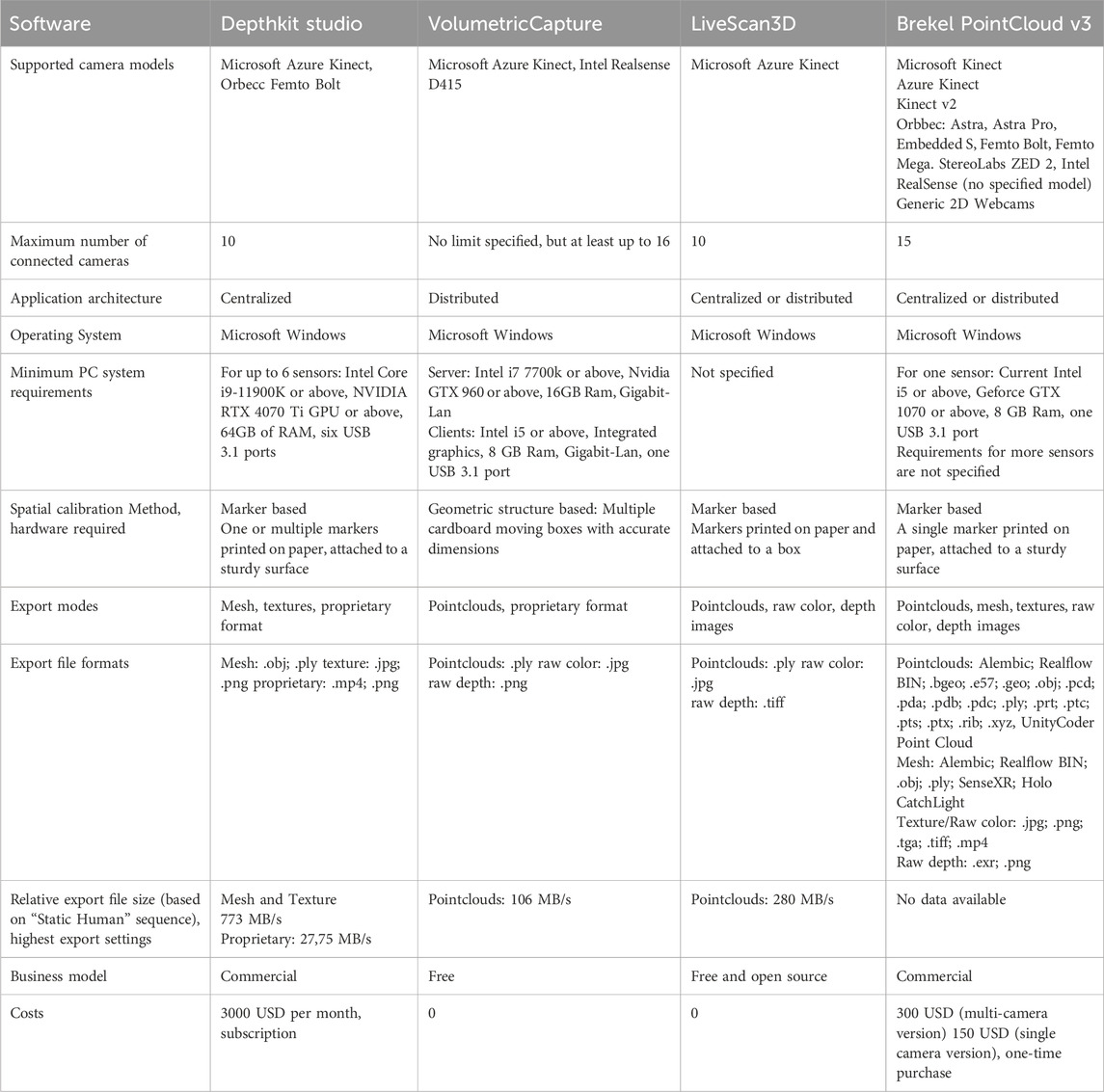
Table 1. Overview of features for all candidates. Not all information about the supported cameras, number of camera and export formats could be verified.
2.2.2 Camera arrangements
A major advantage of sparse-camera setups over traditional dense-camera volumetric capture setups is their adaptability and portability. To test for this adaptivity, we captured footage from a total of three different camera arrangements. The arrangements were selected to represent typical usage scenarios for volumetric video capture systems (Figure 1).
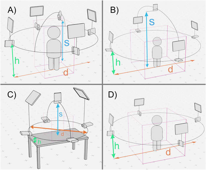
Figure 1. Camera and lighting arrangements used for the benchmark. The diameter of the orbit used to arrange the cameras is marked as d, the height of the orbit from the capture volume ground plane as h and the height of the of the centered overhead camera with s. The capture volume is shown as a pink bounding box. From left to right, top to bottom: Arrangement (A) (d = 2.8 m, h = 1.5 m, s = 1.9 m), Arrangement (B) (d = 4 m, h = 1.5 m, s = 2.8 m), Arrangement (C) (d = 1.2 m, h = 0.2 m, s = 0.8 m), Arrangement (D) (d = 4 m, h = 1.5 m).
2.2.2.1 Camera arrangement A
One of the most common use cases for volumetric capture is to capture a single isolated person who is confined to a limited range of motion, such as sitting or standing in one position. The captured person is often in the role of an instructor, presenter, moderator, or theater performer. For this arrangement, we positioned four cameras in an orbital array around the subject, with an orbital diameter of 2.8 m and a height of 1.5 m above the ground. Each camera was separated by 90° on the orbital plane. To allow for clean face captures, a fifth “hero” camera was placed close to the subject’s face, just above eye level (1.9 m). All cameras were rotated by 90° on their camera axis, as this slightly increases the vertical field of view. LED light panels were placed above each of the cameras in the orbit. The total capture volume for this arrangement is about 1 m * 1 m * 2 m (length × width × height) (Figure 1A)
2.2.2.2 Camera arrangement B
In cases where more than a single person needs to be captured, or when interaction with larger objects is required, the capture volume must be increased. In camera arrangement B, the volume is enlarged to a total size of approximately 2 m * 2 m * 2 m (L × W × H), by increasing the camera orbit diameter to 4 m. As this is a more general arrangement with no specified position for the subjects, the fifth camera was repositioned centrally to a height of 2.8 m above the volume, pointing downwards. The four light panels were again placed above the four cameras in the orbit (Figure 1B).
2.2.2.3 Camera arrangement C
For camera arrangement C, the capture volume has been reduced to about 0.4 m * 0.4 m * 0.4 m (L × W × H). This allows the sensors to be placed closer to a subject, increasing pixel density. This setup is therefore ideal for close-up shots of fine structures, such as hands, hand-object interactions, or faces. At the same time, this presents a challenge to the candidates’ calibration method, which must also adapt to the smaller volume. The camera orbit was decreased to a diameter of 1.2 m at a height of 0.2 m. The fifth camera was placed 0.8 m above the ground, looking down on it. We focused on hand interactions with this arrangement, so all cameras were mounted on a table to act as a ground plane for the capture volume. Two light panels were placed approximately 1.2 m above the scene, facing the capture volume (Figure 1C).
2.2.2.4 Camera arrangement D
Due to limitations in the calibration procedure of the VolumetricCapture software, a fourth unique arrangement had to be created. Arrangement D is identical to Arrangement B, but without the fifth overhead camera. This setup was used for all scenes captured with the VolumetricCapture software (Figure 1D).
2.2.3 Sensor and software settings
While certain settings, particularly the sensor settings, are shared between all tested applications, each software provides a range of modifiers that can improve capture quality. We optimized these settings according to the documentation guidelines and consulted the software’s authors to ensure that the configurations were ideal given the capture environments, maximizing fidelity. Since most applications offer a large number of adjustable parameters, only the settings that deviate from the defaults are documented here. For Depthkit Studio and LiveScan3D, the centralized system mode was used, as it reduced setup time and hardware management complexity. For VolumetricCapture we used the distributed system mode as it doesn’t support a centralized setup.
2.2.3.1 Common and sensor settings
All Azure Kinect units were updated to the firmware version 1.16.110079014 and the Azure Kinect SDK v1.4.1 was installed on all host PCs. The unbinned near field of view (NFOV) mode of the depth sensor of the Azure Kinect units was used for all volumetric capture applications, giving a depth resolution of 640 × 576 pixels and a field of view of 75° in the horizontal axis and 65° in the vertical axis. This mode was selected based on its favorable balance between depth accuracy and resolution and is also recommended by most volumetric capture applications. The color resolution was set to 1,920 × 1,080 pixels, as this was the maximum resolution that could be smoothly handled by the recommended PC hardware specifications. We enabled the Azure Kinect temporal synchronization feature for all applications by connecting the cameras via 3.5 mm audio cables in a daisy-chain configuration. Enabling the synchronization requires switching to manual exposure, which guarantees consistent frame timings across all devices. A manual exposure intensity appropriate for the environment was used to avoid under- or overexpose. The powerline frequency setting was set to 50 Hz, which matches the power frequency in the country where the benchmark was performed. If this parameter is set incorrectly, lights might show as having a flickering or strobing effect in the captured footage.
2.2.3.2 Depthkit studio
Depthkit Studio version 0.8.0 and its accompanying Unity package Depthkit Core Expansion Package Phase 9 were used in the benchmark. The calibration refinement parameters (Spatial Error, Sheer Angle and Temporal stability) will also need to be adjusted for each calibration pass individually but should firmly lean towards the Precision side. For the mesh export settings, the Mesh Density parameter has been set to a value of 200, Depth Bias compensation to 7 mm, Surface Infill to 0 and Surface Smoothing to 5 mm. For the texture export settings, the texture Blend parameter was set to 1, Texture Spill Correction Intensity to 44 and Texture Spill Correction Feather was set to 0.7.
2.2.3.3 LiveScan3D
LiveScan Pre-Release Build v.1.2alpha1 from the BuildingVolumes repository has been used during the benchmarking process. We built a calibration cube according to the instructions and used the Calibration_Cube_4S_A4.txt preset for the configuration. The Depth Map Filter was enabled for all cameras and set to a value of 5.
2.2.3.4 VolumetricCapture
VolumetricCapture v5.0.0 was used for benchmarking. VolumetricCapture relies on several sub dependencies that need to be installed along the main application. RabbitMQ v3.12.13 was used, as well as Erlang Compiler v25.2.3 and Python 3.7. We note that it is important that only Python 3.7 is installed on the host machine, and to follow the instructions in the installations.txt file, instead of the automatic installation during the configuration of the calibration software.
2.2.4 Scenes
Four benchmarking scenes with differing camera arrangements were captured. The duration of each scene was targeted to be approximately 15–20 s. Due to limitations in the calibration procedure of VolumetricCapture, it was not possible to use it with other camera arrangements than arrangement D. This arrangement is not suitable for closeup scenes, therefore the Hand and Hand Interaction could not be captured for this candidate. Table 2 provides a comprehensive overview of the scenes with their corresponding arrangement and candidate:
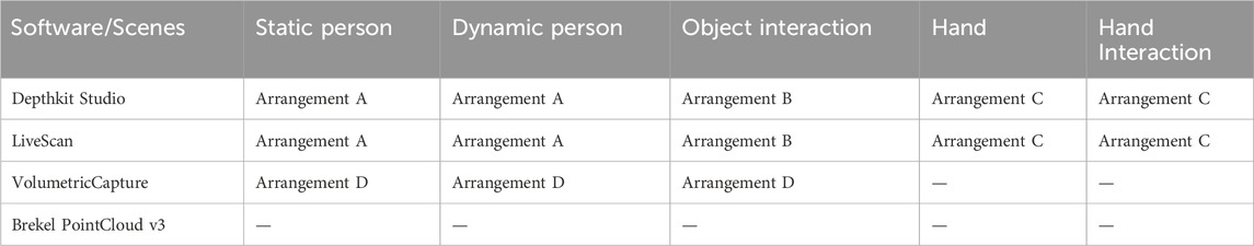
Table 2. Benchmark scene, camera arrangement and candidate correlation.
2.2.4.1 Static person
With this scene, our goal was to provide ideal and non-challenging conditions for the candidates, that would result in captures with high video quality. Camera arrangement A was used to maximize the sensor coverage. The scene shows a single person standing upright with little body motion.
2.2.4.2 Dynamic person
This scene corresponds to Static Person in the general setup and use of camera arrangement A, but the subject makes much more physical movement, particularly through their hands and upper body. These conditions enable us to test the candidate’s ability to handle fast movements and are expected to result in some artifacts.
2.2.4.3 Object interaction
This scene presents a challenge to the candidate’s ability to capture complex interactions between objects within larger volumes. Camera arrangement B, with the largest capture volume, was employed for this scene. This scene shows a small choreography of a person sitting on a chair, who then stands up, walks around the chair and puts on a jacket. They then proceed to lift a small box from the floor and leave the capture volume with it. The presence of various objects in the scene results in more obstructions, leading to fewer cameras observing the same parts of the scene, decreasing data density. Moreover, the larger capture volume reduces data density and the scene is therefore expected to be of lower quality in general compared to other scenes.
2.2.4.4 Hand
This scene uses camera arrangement C, with a relatively small capture volume. As the increased pixel density allows for more granular objects to be captured, we show a single hand in motion, making different gestures. This scene allows us to test the adaptability and scalability of the candidates to more extreme camera arrangements and their ability to visualize finer structures.
2.2.4.5 Hand interaction
The setup in this scene is based on the Hand scene but introduces a more complex hand-object interaction: Using a few wooden blocks, the two hands build a small structure. Candidates are challenged by the increased complexity of the scene, coupled with the presence of fine structures.
2.3 Visual fidelity
Human perception of any media is a highly complex, multidimensional, and subjective experience. Analyzing and rating the overall quality and effect of a specific medium therefore remains a challenging task. In order to keep the subjective and objective evaluation of the captured benchmarks within a manageable context, we decided to rate the footage purely on the basis of visual fidelity. The fidelity of a given medium describes its ability to mimic the source scene as closely as possible. To produce footage with high visual fidelity, sparse camera volumetric video software needs to address sensor errors caused by the hardware itself and fuse multiple camera perspectives into a single coherent image while working with relatively little information compared to dense-camera setups. In order to assess the fidelity of the captured benchmarks, we use both an objective and a subjective approach. Some features of the fidelity can be assessed objectively, such as the accuracy of the spatial calibration and occurrence of certain artifacts. The overall image fidelity, which is the collective effect of many known and unknown factors, remains difficult to assess objectively. For this reason, we conducted a subjective perception study in which participants were asked to rate the fidelity of the candidates on a comparative basis.
2.3.1 Spatial calibration
All volumetric video capture software needs to fuse the image data from multiple sensors into a single consistent representation. At the basis of this process is the transformation of the independent local coordinate system of each sensor into a shared global coordinate system. This process is commonly known as spatial calibration. The final image quality of a volumetric video quickly degrades if the calibration contains even small errors and is therefore critical for fidelity. A variety of approaches have been developed, often using calibration reference objects with known dimensions and features. Beck and Froehlich (2015) proposes a checkerboard-marker based calibration approach, where the color and depth pixels of an individual sensor are directly mapped into a joint coordinate system. Sterzentsenko et al. (2020) utilize a physical geometric structure in combination with shape analysis to estimate sensor poses. We want to familiarize the reader with the approaches used by the candidates, before analyzing the specific implementations.
2.3.1.1 Marker based calibration
Marker based calibration is one of the most widely used calibration approaches. It involves the use of two-dimensional fiducial markers. Common marker formats include ArUco or checkerboard patterns. If the dimensions of the marker and the intrinsic parameters of the camera are known, the relative transformation (position, rotation and scale) between the camera and the marker can be estimated. If two or more sensors can see a marker at the same time, the relative transformation between the sensors can be measured and a shared coordinate system can be established between the sensors. Additional strategies need to be employed in configurations where not all cameras can observe the marker simultaneously. The marker can either be moved from one camera pair to another in a daisy-chained style, or a structure, where markers are visible from any angle can be used. In general, the more observations of a marker at different positions within a captured volume exist, the better the calibration can be estimated.
2.3.1.2 Structure based calibration
Structure based calibration methods harness the ability of depth-sensors to directly capture three-dimensional data of a scene. A structure of known dimensions is constructed and placed in the center of the capture volume, so that all sensors can observe it. The three-dimensional shape of the structure is then searched for within the depth sensor image. The orientation and position of the structure relative to the sensor can be used to infer the position of each sensor. For this method to work, it is important that the structure looks unique from all perspectives, otherwise a false match can occur.
The calibration process is a key component of any volumetric capture workflow and must be performed each time a camera is moved. Accordingly, this does not only affect the final quality, but the convenience of the calibration workflow is also an important usability factor. To quantify the spatial calibration quality of the candidates, the dimensions of captured objects were compared to their known physical dimensions. Since the Azure Kinect provides depth data in metric units, the measurements can be taken directly from the exported sequences. For each of the sequences Dynamic Person, Object Interaction and Hand, we measured the dimensions of the same objects on the X, Y and Z-axes of the Cartesian coordinate system over multiple frames. The values for all axes and samples are averaged into a single value for each scene and candidate. Additionally, we provide the minimum and maximum deviation measured in each scene.
2.3.2 Artifacts of volumetric video
To create the final three-dimensional image, the applications need to fuse observations from many different cameras and sensors into a unified representation. Due to imperfections in the sensor hardware, spatial calibration or post-processing, flaws and imperfections are introduced into the final image. These are commonly referred to as artifacts. We visually inspect the entire benchmark sequences of the candidates for the occurrence of artifacts and describe their occurrence rate, as well as their intensity. In addition, we ask which artifacts dominate the visual appearance of each candidate. To objectively measure the occurrence and intensity of artifacts in volumetric captures, we first need to define the different types of artifacts and their appearance. To achieve higher fidelity, filtering strategies or data refinement can be employed. However, these processes themself can also introduce new artifacts. While artifacts generally result in a lower image fidelity, they might be perceived differently depending on the use case. Artifacts can be desirable in videos used for artistic contexts, such as games, or Virtual reality experiences, but a strong adherence to the ground truth is needed for other use cases, such as medical training, or documentary films.
Figure 2 shows a non-exhaustive collection of the visually most prominent artifacts in the captured benchmark footage, which are described in more detail below. For evaluation purposes we distinguish between the RGBD camera artifacts, data fusion artifacts and visualization artifacts.
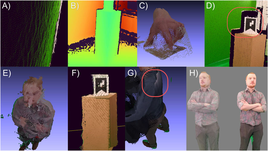
Figure 2. Examples of different types of artifacts. (A) Depth noise on a flat wall, (B) Holes and missing pixels, (C) Flying pixels, (D) Incorrectly projected color, (E) Spatial calibration error, (F) Overlap, (G) Color mismatch, (H) Point cloud (left) and mesh and texture (right) renderings.
2.3.3 RGBD camera artifacts
RGBD cameras, such as the Azure Kinect used in this benchmark are a unit of multiple different optical sensors that need to work together precisely to produce the combined color and depth data streams. While digital color cameras are a well-established technology, depth-sensing cameras are relatively new as a commodity technology. There are different technologies to estimate the depth of a scene, but we focus on the artifacts caused by the Azure Kinect’s near-infrared Time-of-Flight (ToF) technique:
2.3.3.1 Depth noise
Like traditional RGB cameras, ToF sensors also suffer from image noise. This noise is most visible as a high frequency jitter of pixels along the depth axis of the sensor. For the Azure Kinect, this jitter can range from 1 to 8 mm (Rijal et al., 2023) and increases with the distance from the captured objects. In addition to affecting the precision of the depth measurements, this noise is a highly visible artifact in any video footage captured by this system. The noise can be reduced by temporal filters, such as adopted versions of the Kalman Filter (Amamra and Aouf, 2018).
2.3.3.2 Holes or missing pixels
Under certain conditions, the ToF sensor can’t correctly measure the distance in parts of the image, resulting in gaps or holes in parts of the scene. Incorrect measurements can be caused by multipath interference, materials absorbing the infrared laser illumination, or objects being too close or too far from the sensor. Deep neural networks, which have been trained on RGBD image sets can provide a possible solution to this problem (Zhang and Funkhouser, 2018). These networks can complete the depth maps and fill any remaining holes but can also introduce new artifacts and hallucinations.
2.3.3.3 Flying pixels
When depth data is incorrectly placed on the depth axis, pixels appear to float or fly around in the capture volume. Sometimes these are just discrete outlier pixels that look like floating particles. Often, however, these pixels appear more systematically between two objects that are in front of each other. They seem to connect the objects like glue (Tölgyessy et al., 2021). This artifact is particularly present on Azure Kinect devices and is likely caused by errors or inaccuracies in the depth map generation algorithm. Most isolated flying pixels can be filtered by using statistical outlier detection. Flying pixels that occur systematically between two objects can be removed using an erosion filter, which removes all pixels around these objects on the XY image plane.
2.3.4 Data fusion artifacts
Because each camera in a volumetric video setup observes a different perspective of the scene, the volumetric video capture system has to fuse all these perspectives into a coherent representation that accurately represents the ground truth. The fusion algorithm needs to deal with several possible artifacts:
2.3.4.1 Overlapping data
Due to calibration or sensor inaccuracies, data points that are observed by two or more cameras simultaneously will never be perfectly aligned, which results in overlapping. While larger geometric inaccuracies should be addressed with better calibration methods, small overlapping regions can be masked by depth fusion algorithms (Meerits et al., 2018; Newcombe et al., 2011). Similarly, overlapping regions in the color data can be fused by texture fusion algorithms (Waechter et al., 2014).
2.3.4.2 Color mismatch
Even with perfect spatial calibration and no overlapping data, differences in the color sensor data from two cameras can create visual seams. Due to differences in the hardware, color space, exposure, ISO or white balance between sensors, this is often unavoidable to some extent but can be dealt with by color matching (Waechter et al., 2014), band separation (Baumberg, 2002) and smoothing between the two perspectives near the seam.
2.3.4.3 Incorrectly projected color
As the color and depth cameras are in physically different locations, they observe slightly different perspectives of the scene. To fuse both image modalities into a single unified coordinate system, the lens distortion (intrinsics) and the orientation of the sensors relative to each other (extrinsics) must be precisely measured and corrected for. Errors in this calibration process will result in an offset in the color data projected onto the depth pixels. For example, parts of the foreground of a scene might appear projected onto the background. Another possible cause of misprojection is when larger areas of the depth map are missing. In this case, the color information might get incorrectly projected onto nearby geometry instead.
2.3.5 Visualization format
The data captured by the volumetric system needs to be quantized into a format that can be used for storage and playback. Classical representation formats for three-dimensional data in computer graphics include point clouds and meshes, which are also used by the candidates. Each format can produce specific artifacts:
2.3.5.1 Point cloud-based artifacts
Point clouds consist of many discrete, colored points that are located in a three-dimensional coordinate system. The size of the points must be adjusted in relation to the distance of the point of observation to create the appearance of a continuous shape. This illusion quickly breaks down when the distance is changed and can therefore result in artifacts with a patchy appearance. Additionally, volumetric video rendered as a point cloud can appear noisy, as it is composed out of many discrete objects. Rendering the points as splats, where the transparency of the points increases towards its edges, can result in smoother looking visualizations, but is not yet widely supported.
2.3.5.2 Mesh-based artifacts
Mesh-based formats describe 3D objects as continuous surfaces consisting of many small polygons. This format has the advantage of being visually smoother looking, as well as taking advantage of the high-resolution color texture captured by the sensors. Surface reconstruction algorithms are used to create a mesh from the point cloud or depth data, but these require a certain level of information density. Regions of the volumetric image that cannot provide this density, or contain structures that are too thin, may be missing from the mesh. When this happens, the color texture cannot be projected onto the missing geometry and may be incorrectly projected onto other parts of the model.
2.3.6 Perception study setup
The objective visual analysis can only capture certain factors that contribute to the fidelity of a video at a technical level but cannot show how the fidelity of a candidate might be perceived by an audience. For this reason, a subjective fidelity study was conducted to evaluate which candidates are perceived to possess higher fidelity. The design of the study is based on the ITU-T P.910 2022 recommendation Subjective video quality assessment methods for multimedia applications (ITU-T, 2022). As the goal of this study is to compare the fidelity of the candidates relative to each other, and not in a broader context, we used a pair-comparison method (P.910 2022 section 7.4), where participants judge which element in a pair of sequences is preferred. We complemented the pair-comparison method with a simultaneous presentation (SP) (P.910 2022 Annex C) of two sequences from different candidates to facilitate the decision process for participants. This accounts for the fact that volumetric video is a relatively unknown medium with unfamiliar visual patterns and artifacts. The recommendation demands to show the sequences on a traditional two-dimensional display. However, we argue that the experience of the spatial dimension is a crucial factor in the perception of a volumetric medium. Therefore, we implemented the study into an Extended Reality (XR) environment, while keeping other presentation parameters as specified in the recommendation, similar to Subramanyam et al. (2020). We set up a three-dimensional study environment within the Unity3D game engine (Unity Technologies, 2023). As specified in the ITU-T P.910 recommendation, the environment is kept in a neutral gray, except for a blue grid on the virtual floor, to facilitate the navigation and orientation for the participants. Two podiums, which are positioned about 2 m in front of the participants, act as playback locations for the volumetric video. The position and scale of the volumetric videos were adjusted in such a way that both videos are fully visible at the same time, without requiring the user to turn their head. Participants were asked not to leave this centered position during the study but were allowed to move their head in all dimensions. The Depthkit Expansion Package Phase 10 (Scatter, 2024), included with Depthkit Studio was used to playback the scenes for this candidate. As the other candidates do not provide a native playback solution, we used the open-source volumetric video playback solution Unity Geometry Sequence Streamer (BuildingVolumes, 2023). During the study, all benchmark sequences were shown. The Static Person, Dynamic Person and Object Interaction sequences were compared across all candidates, while the Hand and Hand Interaction scenes were only compared across the candidates LiveScan3D and Depthkit Studio. In each sequence, every candidate was paired with every other possible candidate. All candidate pairings were shown twice, with the podium position (left or right) swapped on the second viewing. After one sequence pair finished playing, the participants could interactively vote for their preferred sequence within the XR study environment or choose to watch the sequence again once. Before the participants began the study, they were shown a training sequence, which was not included in the benchmark sequences, to familiarize them to the study procedure and test conditions. Participants were asked to vote solely based on visual fidelity, trying to avoid any bias stemming from the aesthetics or stylization of the footage. The study was conducted with a Meta Quest 3 headset (Meta Platforms, Inc., 2023). The full dataset from the study, along with the code used for data analysis and visualization is provided.
3 Results
3.1 Candidates
3.1.1 Features
Although all candidates share a certain set of core features required for volumetric video capture, the features beyond the required functions vary significantly. Table 1 provides a comprehensive overview for most of the candidates’ features. We were able to test the majority of these features during our benchmark and evaluation phase, but not all features could be verified. This especially applies to the list of supported camera models, the maximum number of cameras and the export formats. The feature list was partially taken from the available documentation and was manually completed during the evaluation process. We recommend reading Table 1 for full information on the feature set of the candidates.
Brekel Pointcloud v3 and Depthkit Studio are both commercial applications. While Depthkit Studio is distributed in a subscription model for 3000 USD per month, access to the open beta of Brekel Pointcloud v3 can be purchased for one time charge of 300 USD. VolumetricCapture and LiveScan3D are freely available on Github2,3, but only the code base of LiveScan3D is open-sourced.
Livescan3D and Depthkit Studio support capture with up to ten Azure Kinect sensors at the time of writing. Brekel Pointcloud v3 supports a wide sensor range, such as the Kinect v1/v2/Azure, Orbecc Astra series, Intel Realsense series and StereoLabs ZED series. VolumetricCapture supports the Intel Realsense D415 in addition to the Azure Kinect. It allows recordings with at least sixteen simultaneous sensors due to its strictly distributed software architecture, where each sensor is connected to its own host PC. LiveScan3D and Brekel Pointcloud v3 can be operated in either a centralized mode, where all sensors are connected to the same PC, or the distributed mode. Depthkit Studio operates only in a centralized mode, which requires a capable host machine. At the same time, only Depthkit Studio allows to post-process the captured video and export it as a textured mesh sequence. The other applications export the video as a nearly unprocessed pointcloud sequence.
3.1.2 User experience
Due to the complexity and novelty of volumetric capture systems, a solid user experience and comprehensive documentation are the foundation for successful volumetric captures. We evaluated the availability and quality of documentation, the usability experience of the graphical user interface (GUI), and at the stability of the system. Particular attention was directed to the spatial calibration methods, which are one of the most time-consuming tasks in the capture pipeline (Section 3.2.1).
Depthkit Studio provides extensive and comprehensive documentation resources in the form of a website, video tutorials and a community forum. We found the GUI to be intuitive and well-structured and didn’t experience any crashes or errors. The software ran smoothly and was easy to set up with the provided installers. Depthkit Studio uses a marker-based calibration approach. One or more ArUco marker boards need to be printed out in DIN A3 format and attached to a solid surface. The cameras are calibrated in daisy chained pairs. For each pair, multiple samples of the marker must be taken throughout the capture volume. To capture a sample, the marker must be kept stationary and a sample phase needs to be manually activated for approximately 5 s. Due to the number of samples that need to be taken, the calibration routine for five cameras took approximately 15–25 min to complete. While the material requirements are low and the process works well, the calibration routine took by far the longest compared to the other applications. Not every calibration run produces the desired results and may have to be repeated, resulting in calibration times of up to an hour.
LiveScan3D only provides little documentation, which is scattered throughout the software repository and is therefore difficult to find. We found the GUI to be generally clear and intuitive, although the program did occasionally freeze or crash. For calibration, LiveScan3D uses a marker-based approach, that requires the construction of a multi-marker calibration cube. The calibration cube can be made of different materials and its size can be adjusted for different capture scenarios. This initial construction step is time-consuming and difficult as the dimensions and angles need to be carefully observed. The calibration cube must be placed in a part of the scene that is visible to all cameras and is then automatically recognized by the software. It was sometimes necessary to adjust the lighting for the marker to be recognized. The calibration routine itself takes about 2 min. There is also an option to refine the calibration using an iterative closest point algorithm, but this did not reliably improve the calibration quality. While the calibration routine itself is quick, the initial construction step may make it difficult for users without access to laser cutters or 3D printers to achieve a successful calibration.
VolumetricCapture provides robust online documentation and support on its Github repository page. Of all the applications, VolumetricCapture offers the most sophisticated approach to the distributed architecture. The clients can be run completely headless, with no peripherals and no direct interaction with the clients other than physically turning them on and off. To configure the distributed system, multiple sub-programs, ports and services needed to be set up for each client PC. We found the GUI rather difficult to use, due to the complex layout and many non-functioning elements. Disconnections and crashes were regular problems and could only be resolved by restarting the application. VolumetricCapture is the only candidate to employ a structure-based calibration approach. The structure consists of four IKEA Jättene moving boxes, which have been discontinued in production. Due to the dimensions of the box being prescribed, they had to be manually reconstructed from flat cardboard. The calibration routine is not included with the binaries and must be downloaded and installed via a Python script. We had to implement workarounds to run the script successfully. For non-technical users, this setup step can be particularly difficult. The calibration routine itself can be performed in about 2 min, including the structure setup, but often fails and needs to be repeated multiple times.
Brekel PointCloud v3 comes with an installer that makes initial setup easy, and comprehensive documentation in the form of an offline PDF document. The wide range of supported features results in a sometimes cluttered and overloaded, but well-structured interface. Although the application ran smoothly and without crashes, we were unable to capture benchmark footage with this candidate due to a bug in the calibration process. We have confirmed the existence of this bug with the author of the application to rule out operational errors on our part. Brekel Pointcloud v3 is advertised as being in a beta version on the manufacturer’s website.
3.2 Visual fidelity
All five scenes were successfully captured for LiveScan3D and Depthkit Studio. Due to limitations in the calibration approach used for VolumetricCapture, only three scenes could be captured. Figures 3, 4 show a visual overview of all the footage that was captured during the benchmark phase and subsequently used for the analysis and study, including the ground truth captured with the color camera of the Kinects. A video showing these scenes in motion is available.4 In some scenes, green areas might be noticeable. These are the result of the presence of a green screen in the recording studio, which is falsely being projected onto parts of the capture. This is an artifact that would occur in any capture environment but is more noticeable here due to the vibrant color.
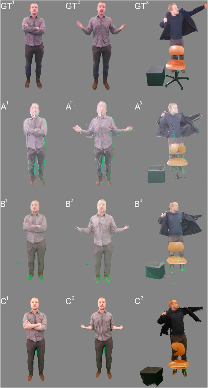
Figure 3. Frames of the captured benchmark footage with all candidates. From top to bottom: GT) Ground truth, A) VolumetricCapture, B) LiveScan3D, C) Depthkit Studio. From left to right: 1) Static Person scene, 2) Dynamic Person scene, 3) Object Interaction scene.
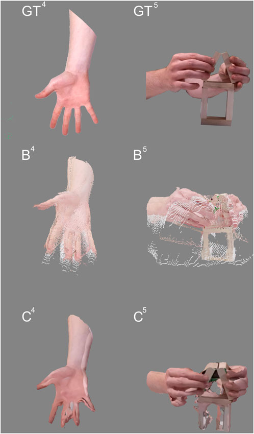
Figure 4. Frames of the captured benchmark footage with camera arrangement C. From top to bottom: GT) Ground truth, B) LiveScan3D, C) Depthkit Studio. From left to right: 4) Hand scene, 5) Hand Interaction scene.
3.2.1 Spatial calibration analysis
The spatial calibration was measured for each scene individually by calculating the average deviation in centimeters between the dimensions of virtual objects and their real counterparts. The results show that the size of the capture volume is directly correlated to the calibration error, with a larger capture volume resulting in a larger error (Figure 5). Depthkit Studio consistently showed the least amount of deviation. For the Dynamic Person scene, the average deviation was 8 mm, for Object Interaction 13 mm and for Hand 2 mm. The measured deviation for LiveScan3D is on average twice as large as in Depthkit Studio. The Dynamic Person scene measured an average deviation of 17 mm, the Object Interaction scene an average deviation of 21 mm and the Hand scene an average deviation of 4 mm. While the camera arrangement for VolumetricCapture did not change between scenes, the calibration accuracy varied by a large margin, with the Dynamic Person scene showing a low accuracy with 26 mm of deviation but performing much better in the Object Interaction scene with 15 mm deviation. This shows that theoretically a competitive calibration accuracy can be achieved with the employed calibration approach, but the accuracy could not be reliably reproduced between different takes in our benchmarking setup, even though repeated attempts were made for each scene.
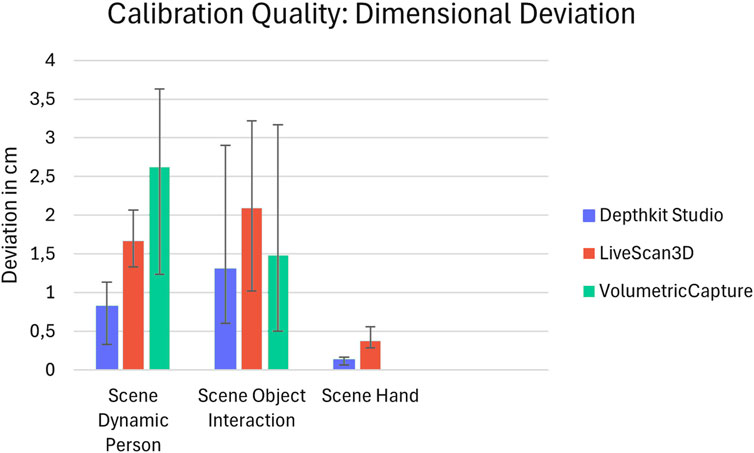
Figure 5. The calibration accuracy of the candidates is assessed by calculating the average deviation in centimeters between the dimensions of virtual objects and their real counterparts. The ranges show the minimum and maximum deviation measured over several frames.
3.2.2 Artifact analysis
We conducted a thorough examination of all the benchmark footage captured, specifically focusing on identifying visual artifacts. We found that each candidate exhibits a different set of artifacts that, in sum, dominate the overall appearance of the volumetric video. The most prominent artifacts for each candidate are presented along with their frequency of occurrence and intensity.
Depthkit Studio is the only application in the benchmark that renders the captured video in a mesh and texture format. This strategy seems to solve some of the artifacts that point cloud-based approaches exhibit. Videos produced with Depthkit Studio appear to be more coherent, contain less noise, and blend overlapping sensor data more elegantly. However, the surface reconstruction algorithm implemented in the application has difficulties catching finer details, such as fingers or thin objects. These parts often disappear completely from the reconstruction. Consequently, the color texture of the missing geometry is sometimes incorrectly projected onto surrounding geometry in the scene. These artifacts were present throughout the entire benchmark footage. A less common color mismatch artifact affects the blend between overlapping sensor data, making the seams more noticeable. Despite these artifacts, the footage overall exhibits a smooth and coherent look, and objects are mostly faithfully reconstructed (Figure 6).
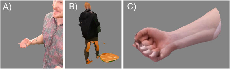
Figure 6. Prominent artifacts in footage captured with Depthkit Studio. (A) Missing geometry, (B) Incorrectly projected color texture, (C) Color mismatch.
LiveScan3D renders the captured footage as point cloud sequence. Compared to the mesh and texture videos of Depthkit Studio, the point cloud footage appears grainy and noisy, but can capture finer detail. The accuracy of the spatial calibration is less precise than with Depthkit Studio but better than VolumetricCapture. This is noticeable throughout all scenes, with more detailed regions appearing to be duplicated and shifted. Objects often show trails of flying pixels, making silhouettes harder to detect. There is jitter and color mismatch in areas where sensor data overlap. LiveScan3D images generally show sufficient detail in regions such as the face or hands, and objects appear cohesive, but the artifacts can cause objects to appear slightly distorted and noisy especially in smaller regions (Figure 7).
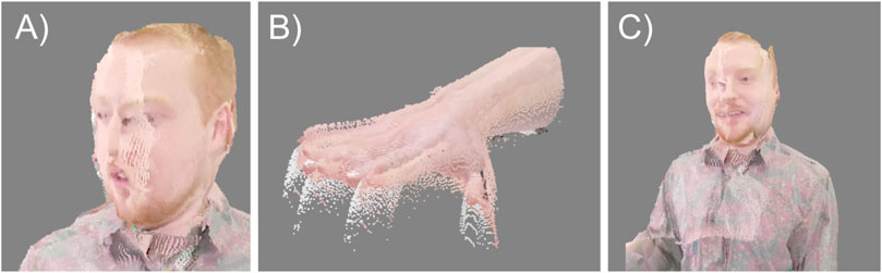
Figure 7. Artifacts in LiveScan3D videos: (A) Imprecise spatial calibration, (B) flying pixels, (C) overlapping sensor data.
VolumetricCapture shows artifacts similar to LiveScan3D, but often more pronounced. Due to the limitations of the calibration routine, the sensors in the Static Person and Dynamic Person scene had to be positioned further away than in the other applications, reducing the resolution in the captures. In cases where good calibrations could not be achieved, small to medium-sized details appear blurred and distorted, such as the eyes, ears and nose of a face. Incorrectly projected colors appear as large seams that extend throughout the video. Flying pixels are not only visible near objects but are scattered throughout the entire capture volume. The general context and content of the scene is recognizable, and larger objects are correctly reconstructed. However, VolumetricCapture also captured some details that were not visible in other candidates; for example, the leg of a chair (Figure 8).
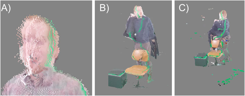
Figure 8. Artifacts in VolumetricCapture footage: (A) Imprecise spatial calibration, (B) incorrectly projected colors, (C) flying pixels (Point size was slightly increased for illustration purposes).
3.3 Subjective study results
For the subjective fidelity perception study, we asked participants to rate the volumetric video solely on its visual fidelity. We selected a cohort familiar with the processes involved in creating and analyzing computer graphics. 19 participants were recruited from a game design graduate program. All 19 participants completed the study, with an average session length of 10–15 min. Each participant voted 22 times during the study, for a total of 418 votes. In cases where participants chose a different candidate during the repeated presentation of a pair of comparisons, both votes were invalidated. This affected 66 votes or 15.7% of the votes. Depthkit Studio and LiveScan3D were compared 190 times (160 valid), Depthkit Studio and VolumetricCapture 114 times (98 valid), VolumetricCapture and LiveScan3D 114 times (94 valid). To assess statistical significance, we conducted goodness-of-fit tests for each evaluation scenario. As a measure, we use the sum of valid votes that each framework received from all participants. For scenes where all three software candidates produced sequences (Static scene, Dynamic scene, Object scene), Pearson’s chi-squared (χ2) tests were performed. For the Hand and Jenga scene, where only LiveScan3D and Depthkit Studio were able to capture footage, Barnard’s exact test was used to account for the smaller sample size of votes. In the tests, we compare the observed number of recorded votes to the expected number, assuming an equal distribution of votes for each framework. Our null hypothesis assumes that the recorded numbers of votes follow a random distribution, while the alternative hypothesis is expected to have differing distribution proportions. After adjusting p-values to account for multiple comparisons with the Benjamini–Hochberg procedure, we rejected the null hypothesis in all scenarios, indicating statistically significant differences in the distribution of recorded votes at a significance level of α = 5%. The results of the significance tests are presented in Table 3. All statistical analyses were performed in python (version 3.12.1) with the packages SciPy (version 1.14.1) for the hypothesis testing and Pinguin (version 0.5.5) for multiple comparisons adjustment.
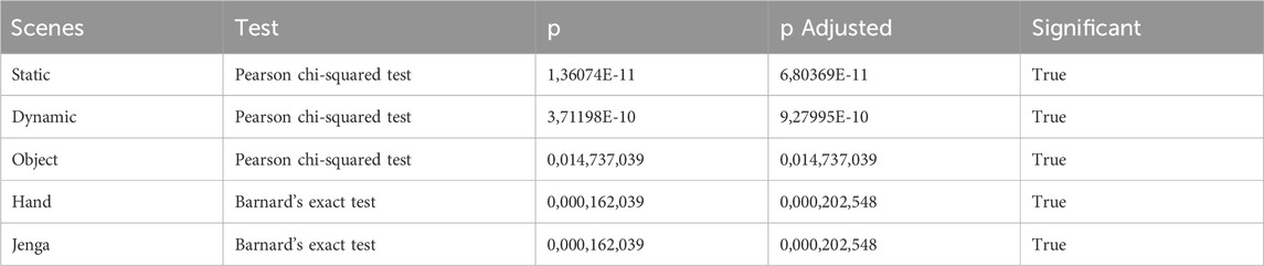
Table 3. Significance test results.
The percentage vote distribution among the candidates is shown in Figure 9 and the total number of votes is shown in Table 4. When comparing Depthkit Studio with LiveScan3D, Depthkit Studio was preferred, with 90% (144 votes) of the votes. Depthkit Studio was slightly less preferred, but also strongly preferred over VolumetricCapture with 84% (82 votes) of the votes. LiveScan3D was strongly preferred over VolumetricCapture with 78% (74 votes) in favor. When comparing across individual scenes, the votes in the Static Person and Dynamic Person scene are similarly distributed. Depthkit Studio receives on average 64% of the votes, LiveScan3D 26% and VolumetricCapture 9%. Only in the Object Interaction scene, the vote distribution was more evenly distributed, with LiveScan3D receiving about 35% and VolumetricCapture receiving about 19% of the votes compared to Depthkit Studio. For the close-up scenes Hand and Hand Interaction, Depthkit Studio continued to be almost exclusively preferred over LiveScan3D with 94% of the votes (Figure 10).
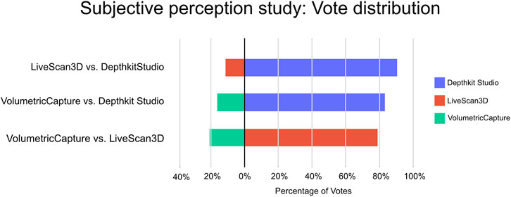
Figure 9. Vote Distribution in the subjective Perception study.
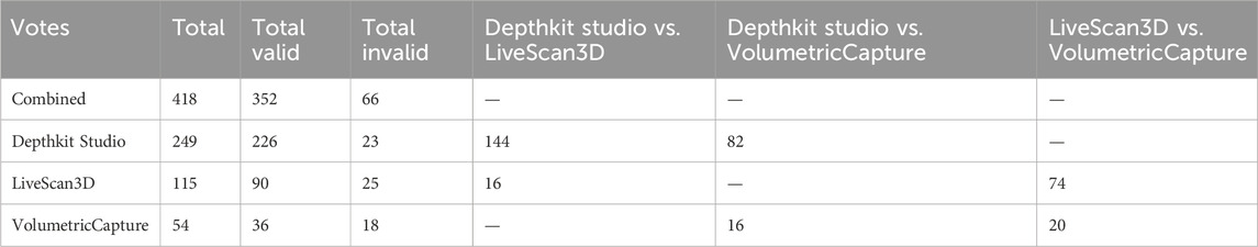
Table 4. Fidelity perception study total vote counts.
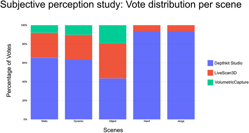
Figure 10. Vote distribution per scene in the subjective perception study.
4 Discussion
4.1 Result interpretation
Depthkit Studio shows the best results across all measured parameters. It scores highest in spatial accuracy, shows the least intensive artifacts and is the preferred candidate in the subjective perception study. We also found Depthkit Studio to be the most accessible candidate, and therefore suited for users novel to the field of volumetric video. At the same time, Depthkit Studio is the most expensive application, with a price tag of 3000 USD per month. This may be at the edge of what is considered low cost or affordable. We would therefore recommend Depthkit Studio to users who are confident that a sparse RGBD-camera volumetric video setup meets the needs of their use case and want to extract the highest possible fidelity from their system. In terms of fidelity, LiveScan3D ranks below Depthkit Studio by a larger margin, but above VolumetricCapture. Hence, we can recommend LiveScan3D as a solid entry point for beginning with volumetric captures, when the highest fidelity is not strictly required. As LiveScan3D can be modified due to the available source code, it is a suitable platform for volumetric video research and experimentation. VolumetricCapture is available as free, but proprietary software. It is specialized to be used in a distributed system mode. This offers advantages for certain use cases, with a high (>10) number of sensors and large capture volumes, or when only low-performance hardware is available. At the same time, this distributed approach is labor-intensive with regard to hardware and software setup, making it difficult to recommend this application to first-time users, even though it is well documented. We can therefore only recommend VolumetricCapture in use cases, where a high number of sensors and large capture volumes are required.
The results of the conducted survey show that participants preferred the footage of Depthkit Studio, which is the only candidate that employs heavy use of post-processing filters and a mesh and texture-based rendering. Results do not provide insights into which of these aspects contribute more to the visual fidelity, but the work of Zerman et al. (2019) suggests that a mesh-based visualization is preferred over a point cloud based visualization, provided that it is encoded with a high enough bitrate. Accurate calibration seems to have a rather large effect on the visual quality as well. Depthkit Studio consistently showed the least deviation in calibration accuracy across all scenes and was also the most favorably rated application for fidelity.
Our results indicate to developers of volumetric video applications that encoding their captures in a mesh-based format, the use of filters and a spatial calibration methods with high accuracy are advantageous for visual fidelity.
4.2 Method limitations
Although our proposed benchmark environment was designed to capture footage in a variety of scenarios, it primarily focused on capturing people and their interaction with objects. The benchmark could be expanded to include a wider variety of scenes and environments, such as outdoor settings, capturing entire environments rather than individual subjects, or testing under challenging lighting conditions. Additionally, the benchmark only evaluates how the applications perform relative to each other under identical capture conditions. However, each application may perform differently when the capture environment is adapted to its individual strengths and weaknesses, such as by using more sensors, alternative sensor models or different camera configurations. While our captures provide a general estimate of how the applications perform “in the wild,” further improvements in visual quality are certainly achievable with tailored adjustments.
Our approach to measuring spatial accuracy provides some basic estimation about image fidelity but lacks detailed technical parameters. Similarly, the artifact analysis lacks a quantifiable measurement of artifact intensity. This may be sufficient for a relative visual perception analysis between captures, but it lacks detailed objective parameters that are required when measuring volumetric videos on a larger scale.
Unlike other publications that have presented visual perception studies of volumetric videos using more nuanced rating scales, our study used only a binary voting system to capture the impressions of the participants. This approach forces participants to clearly choose a single candidate, even if the perceived difference in fidelity is small. This is sufficient to determine which system is relatively preferred over the other, but it doesn’t show how large the differences in perceived fidelity between the candidates are. Additionally, our subject pool is limited to a small, homogenous group from a single profession (game designers). Influenced by their domain knowledge, this group might have a different definition of high fidelity than the general population, therefore the results of our study might not be applicable to a broader audience. Re-conducting this study with a more nuanced rating scale and a more diverse study pool could provide better insights into which aspects contribute most to providing a sense of high fidelity. The UI and UX analysis of the tested systems could benefit from a systemic evaluation through a user study, as the usability has only been evaluated internally, by a group of technically skilled experts in the field of volumetric capture. Novice users may experience more challenges or would rate the usability of the candidates differently. A usability study could provide valuable insights into how volumetric capture workflows should be designed to help adaptability and efficient usage. Finally, this paper can only capture the state of knowledge in the field at the time of publication. Due to the rapid advances in this relatively young field, the concrete results of the fidelity analysis have a certain expiration date, although we believe that the proposed benchmark itself will be viable for future iterations of sparse camera volumetric video capture systems.
4.3 Outlook
Although significant advances have been made in visual fidelity, the overall image quality of sparse camera volumetric video capture applications is not yet sufficient for many use cases with higher demands. Dense camera studio captures can provide photorealistic high-fidelity captures today, but are not accessible to most researchers, creators and developers due to their high costs. This is not likely to change any time soon. Affordable sparse camera systems not only fill a niche of lower cost video creation but help to raise awareness for the field of spatial imaging. Certainly, further research and investment into low-cost sparse camera systems is needed to improve volumetric video creation. Better RGBD cameras could provide higher depth resolutions and depth stability, and the software can improve visual fidelity by deploying solid filtering and fusion pipelines, as Depthkit Studio shows.
However, RGBD cameras are only one of many possible capture solutions in this emerging field. Monocular depth estimation algorithms have seen major developments in recent years and are already deployed for certain VFX tasks, such as scene relighting or masking. While being a relatively new technique, 4D foundation models have been shown to generate impressive scene depth from only sparse image inputs as well. If these models are proven useful for sparse camera volumetric video capture, specialized and expensive RGBD sensors, might become superfluous. This could further improve accessibility for volumetric video capture. As indicated by the subjective fidelity study, the visualization format of the captured data has a palpable impact on the perceived fidelity. New volumetric visualization formats, such as Gaussian Splatting, remedy classical weaknesses of traditional visualization formats such as transparent, reflective or caustic surfaces.
Although these techniques are new, they rely on the same underlying infrastructure as RGBD-camera based capture workflows, such as spatial calibration, temporal synchronization, data streaming, and fusion. Current sparse camera volumetric video applications are therefore ideally suited to adapt these new techniques. It will be interesting to see which techniques in this rapidly developing field will prevail and how they will contribute to a more accessible and higher fidelity volumetric video creation.
Data availability statement
The virtual reality study environment is available on the GitHub repository of Experimental Surgery, Charité - Universitätsmedizin Berlin: https://github.com/ExperimentalSurgery/Volumetric_Video_Comparision_Study. The study results and analysis are available on the following repository: https://zenodo.org/records/13920279. The datasets generated for this study, mainly the volumetric video captures, are too large in size (>100GB) to be reasonably stored in a permanent repository. The datasets are available without restrictions upon request. To access the data, please contact the corresponding author.
Author contributions
CR: Conceptualization, data curation, formal analysis, investigation, methodology, project administration, resources, software, validation, visualization, writing–original draft, writing–review and editing. IMS: funding acquisition, supervision,validation, writing–original draft, writing–review and editing, visualization. MQ: funding acquisition, supervision, validation, writing–original draft, writing–review and editing, conceptualization, project administration, resources.
Funding
The authors declare that financial support was received for the research, authorship, and publication of this article. The authors acknowledge the support of the Cluster of Excellence Matters of Activity. Image Space Material funded by the German Research Foundation (grant no. EXC2025–390648296) and from the Federal Ministry of Education and Research. project GreifbAR: Skillful interaction of user hands and fingers with real tools in mixed reality worlds (grant no. 16SV8753).
Acknowledgments
We would like to thank Dr. Zeynep Akbal, Karl Eisenträger, Christoph Rüger and Dana Ruck for their guidance and review during the writing of this article.
Conflict of interest
The authors declare that the research was conducted in the absence of any commercial or financial relationships that could be construed as a potential conflict of interest.
Publisher’s note
All claims expressed in this article are solely those of the authors and do not necessarily represent those of their affiliated organizations, or those of the publisher, the editors and the reviewers. Any product that may be evaluated in this article, or claim that may be made by its manufacturer, is not guaranteed or endorsed by the publisher.
Footnotes
1https://doi.org/10.5281/zenodo.13920279 [Accessed 11 October 2024].
2https://github.com/VCL3D/VolumetricCapture [Accessed 22 March 2024].
3https://github.com/BuildingVolumes/LiveScan3D [Accessed 22 March 2024].
4https://doi.org/10.5281/zenodo.13908942 [Accessed 10 October 2024].
References
Alain, M., Zerman, E., Ozcinar, C., and Valenzise, G. (2023). “Introduction to immersive video technologies,” in Immersive video technologies (Elsevier), 3–24. doi:10.1016/B978-0-32-391755-1.00007-92
Amamra, A., and Aouf, N. (2018). GPU-based real-time RGBD data filtering. J. Real-Time Image Proc 14 (14), 323–340. doi:10.1007/s11554-014-0453-7
Barron, J. T., Mildenhall, B., Verbin, D., Srinivasan, P. P., and Hedman, P. (2022). “Mip-NeRF 360: unbounded anti-aliased neural radiance fields,” in 2022 IEEE/CVF Conference on Computer Vision and Pattern Recognition (CVPR), New Orleans, LA, June 18–24, 2022 (IEEE), 5460–5469. doi:10.1109/CVPR52688.2022.00539
Baumberg, A. (2002). “Blending images for texturing 3D models,” in Procedings of the British machine vision conference 2002 (Cardiff, United Kingdom: British Machine Vision Association), 38.1–38.10. doi:10.5244/C.16.38
Beck, S., and Froehlich, B. (2015). “Volumetric calibration and registration of multiple RGBD-sensors into a joint coordinate system,” in 2015 IEEE Symposium on 3D User Interfaces (3DUI), Arles, France, March 23-24, 2015 (IEEE), 89–96. doi:10.1109/3DUI.2015.7131731
Bhat, S. F., Birkl, R., Wofk, D., Wonka, P., and Müller, M. (2023). ZoeDepth: zero-shot transfer by combining relative and metric depth. ArXiv. doi:10.48550/ARXIV.2302.12288
Bochkovskii, A., Delaunoy, A., Germain, H., Santos, M., Zhou, Y., Richter, S. R., et al. (2024). Depth Pro: sharp monocular metric depth in less than a second. ArXiv. doi:10.48550/arXiv.2410.02073
Bönsch, A., Feng, A., Patel, P., and Shapiro, A. (2019). “Volumetric video capture using unsynchronized, low-cost cameras,” in Proceedings of the 14th international joint conference on computer vision, imaging and computer graphics theory and applications (Prague, Czech Republic: VISIGRAPP), 255–261. doi:10.5220/0007373202550261
BuildingVolumes (2023). Unity geometry sequence streamer. Github. Available at: https://buildingvolumes.github.io/Unity_Geometry_Sequence_Streaming/(Accessed March 22, 2024).
Chibane, J., Bansal, A., Lazova, V., and Pons-Moll, G. (2021). “Stereo radiance fields (SRF): learning view synthesis for sparse views of novel scenes,” in 2021 IEEE/CVF Conference on Computer Vision and Pattern Recognition (CVPR), Nashville, TN, June 20–25, 2021 (IEEE), 7907–7916. doi:10.1109/CVPR46437.2021.00782
Jin, Y., Hu, K., Liu, J., Wang, F., and Liu, X. (2024). From capture to display: a survey on volumetric video. ArXiv. doi:10.48550/arXiv.2309.05658
Kerbl, B., Kopanas, G., Leimkühler, T., and Drettakis, G. (2023). “3D Gaussian splatting for real-time radiance field rendering,” in 2023 ACM transaction on graphics, 1–14. doi:10.1145/3592433
Kowalski, M., Naruniec, J., and Daniluk, M. (2015). “Livescan3D: a fast and inexpensive 3D data acquisition system for multiple Kinect v2 sensors,” in 2015 International Conference on 3D Vision, Lyon, October 19–22, 2021 (IEEE), 318–325. doi:10.1109/3DV.2015.43
Meerits, S., Thomas, D., Nozick, V., and Saito, H. (2018). FusionMLS: highly dynamic 3D reconstruction with consumer-grade RGB-D cameras. Comp. Vis. Media 4, 287–303. doi:10.1007/s41095-018-0121-0
Newcombe, R. A., Izadi, S., Hilliges, O., Molyneaux, D., Kim, D., and KinectFusion, D. (2011). “Real-time dense surface mapping and tracking,” in 2011 10th IEEE International Symposium on Mixed and Augmented Reality, Basel, Switzerland, October 26–29, 2011 (IEEE), 127–136. doi:10.1109/ISMAR.2011.6092378
Rijal, S., Pokhrel, S., Om, M., and Ojha, V. P. (2023). Comparing depth estimation of azure Kinect and Realsense D435i cameras. doi:10.2139/ssrn.4597442
Scatter (2024). Unity expansion package. Available at: https://www.depthkit.tv/unity-expansion-package (Accessed March 22, 2024).
Sterzentsenko, V., Doumanoglou, A., Thermos, S., Zioulis, N., Zarpalas, D., and Daras, P. (2020). “Deep soft procrustes for markerless volumetric sensor alignment,” in 2020 IEEE Conference on Virtual Reality and 3D User Interfaces (VR), Atlanta, GA, March 22–26, 2020 (IEEE), 818–827. doi:10.1109/VR46266.2020.00106
Sterzentsenko, V., Karakottas, A., Papachristou, A., Zioulis, N., Doumanoglou, A., Zarpalas, D., et al. (2018). “A low-cost, flexible and portable volumetric capturing system,” in 2018 14th International Conference on Signal-Image Technology and Internet-Based Systems (SITIS), Las Palmas de Gran Canaria, Spain, November 26–29, 2018 (IEEE), 200–207. doi:10.1109/SITIS.2018.00038
Subramanyam, S., Li, J., Viola, I., and Cesar, P. (2020). “Comparing the quality of highly realistic digital humans in 3DoF and 6DoF: a volumetric video case study,” in 2020 IEEE Conference on Virtual Reality and 3D User Interfaces (VR), Atlanta, GA, March 22–26, 2020 (IEEE), 127–136. doi:10.1109/VR46266.2020.00031
Tölgyessy, M., Dekan, M., Chovanec, Ľ., and Hubinský, P. (2021). Evaluation of the azure Kinect and its comparison to Kinect V1 and Kinect V2. Sensors 21, 413. doi:10.3390/s21020413
Truong, P., Rakotosaona, M.-J., Manhardt, F., and Tombari, F. (2023). “SPARF: neural radiance fields from sparse and noisy poses,” in 2023 IEEE/CVF Conference on Computer Vision and Pattern Recognition (CVPR), Vancouver, BC, June 17-24, 2023 (IEEE), 4190–4200. doi:10.1109/CVPR52729.2023.00408
Waechter, M., Moehrle, N., and Goesele, M. (2014). “Let there Be color! Large-scale texturing of 3D reconstructions,” in ECCV 2014 lecture notes in computer science (Springer International Publishing), 836–850. doi:10.1007/978-3-319-10602-1_54
Wang, S., Leroy, V., Cabon, Y., Chidlovskii, B., and Revaud, J. (2024). “DUSt3R: geometric 3D vision made easy,” in Proceedings of the IEEE/CVF Conference on Computer Vision and Pattern Recognition (CVPR), Seattle, WA, June 16-22, 2024, 20697–20709. doi:10.1109/CVPR52733.2024.01956
Yang, L., Kang, B., Huang, Z., Xu, X., Feng, J., and Zhao, H. (2024). Depth anything: unleashing the power of large-scale unlabeled data. arXiv. doi:10.48550/ARXIV.2401.10891
Zerman, E., Gao, P., Ozcinar, C., and Smolic, A. (2019). Subjective and objective quality assessment for volumetric video compression. Electron. Imaging 31, 323-1–323-7. doi:10.2352/ISSN.2470-1173.2019.10.IQSP-323
Zerman, E., Ozcinar, C., Gao, P., and Smolic, A. (2020). “Textured mesh vs coloured point cloud: a subjective study for volumetric video compression,” in 2020 Twelfth International Conference on Quality of Multimedia Experience (QoMEX), Athlone, Ireland, May 26-28, 2020 (IEEE), 1–6. doi:10.1109/QoMEX48832.2020.9123137
Zhang, J., Herrmann, C., Hur, J., Jampani, V., Darrell, T., Cole, F., et al. (2024). MonST3R: a simple approach for estimating geometry in the presence of motion. Arxiv:2410.03825. doi:10.48550/arXiv.2410.03825
Keywords: volumetric video, depth camera, visual fidelity, benchmark, user experience
Citation: Remde C, Sauer IM and Queisner M (2025) Sparse camera volumetric video applications. A comparison of visual fidelity, user experience, and adaptability. Front. Signal Process. 5:1405808. doi: 10.3389/frsip.2025.1405808
Received: 23 March 2024; Accepted: 23 January 2025;
Published: 10 March 2025.
Edited by:
Pan Gao, Nanjing University of Aeronautics and Astronautics, ChinaCopyright © 2025 Remde, Sauer and Queisner. This is an open-access article distributed under the terms of the Creative Commons Attribution License (CC BY). The use, distribution or reproduction in other forums is permitted, provided the original author(s) and the copyright owner(s) are credited and that the original publication in this journal is cited, in accordance with accepted academic practice. No use, distribution or reproduction is permitted which does not comply with these terms.
*Correspondence: Christopher Remde, Y2hyaXN0b3BoZXIucmVtZGVAY2hhcml0ZS5kZQ==