 Shoei Hattori
 Shura Suzuki
  Akira Fukuhara
  Takeshi Kano
  Akio Ishiguro
 - 1Division for Interdisciplinary Advanced Research and Education, Tohoku University, Sendai, Japan
- 2Research Institute of Electrical Communication, Tohoku University, Sendai, Japan
- 3Department of Electrical Engineering, Tohoku University, Sendai, Japan
- 4Japan Society for the Promotion Science, Tokyo, Japan
- 5School of Systems Information Science, Future University Hakodate, Hakodate, Japan
This paper explores the applicability of bicycle-inspired balance control in a quadruped robot model. Bicycles maintain stability and change direction by intuitively steering the handle, which induces yaw motion in the body frame and generates an inertial effect to support balance. Inspired by this balancing strategy, we implemented a similar mechanism in a quadruped robot model, introducing a yaw trunk joint analogous to a bicycle’s steering handle. Simulation results demonstrate that the proposed model achieves stable high-speed locomotion with robustness against external disturbances and maneuverability that allows directional changes with only slight speed reduction. These findings suggest that utilizing centrifugal force plays a critical role in agile locomotion, aligning with the movement strategies of cursorial animals. This study underscores the potential of bicycle balance control as an effective and straightforward control approach for enhancing the agility and stability of quadruped robots as well as potentially offering insights into animal motor control mechanisms for agile locomotion.
1 Introduction
Quadruped robots are increasingly being integrated into various industrial applications (Bjelonic et al., 2022). These robots have demonstrated remarkable versatility in tasks such as inspection, exploration, and patrolling. Their capability to select ground contact points enhances their adaptability on uneven and unstructured terrains, offering a notable advantage over wheeled and tracked robots. However, quadruped robots encounter distinct challenges in maneuverability compared to their wheeled and tracked counterparts (Ali et al., 2016). This limitation is primarily due to the intermittent ground contact of their legs and the greater shift in the center of mass during movement (Yongbin et al., 2022). Advancements in balance and turning control mechanisms are essential to further improve the mobility and agility of quadruped robots.
A hybrid approach that integrates features of wheeled systems has shown potential for enhancing the locomotion performance of quadruped robots. For instance, wheeled-legged robots use wheels as end effectors to traverse flat terrain with greater efficiency. The addition of actuated wheels allows legged robots to achieve efficient movement while preserving their ability to navigate rough and uneven terrains (Bjelonic et al., 2019; 2021; Klamt and Behnke, 2017). In contrast, passive wheels offer a solution to reduce energy consumption and robot weight (Hirose and Takeuchi, 1996; Endo and Hirose, 2012; Bellegarda et al., 2018). These studies underscore the considerable advantages of hybrid systems. However, incorporating wheel end effectors adds complexity to both the mechanical design and motor control required for effective legged locomotion.
This study introduces an alternative approach that leverages the advantages of both wheeled and legged systems. Specifically, we draw inspiration from the balance control mechanism of bicycles (Åström et al., 2005; Kooijman et al., 2011). Bicycles maintain stability and navigate direction by intuitively steering the handle, which induces a yaw motion in the body frame and generates centrifugal force. By utilizing this force, bicycles achieve smooth and stable directional changes, even at high speeds. Based on this balance control principle, we hypothesized that applying a steering mechanism for trunk control in quadruped robots could enhance their agility and mobility. In other words, instead of integrating features of wheeled systems into the end effectors, we incorporated them into the robot’s body frame.
This paper presents a quadruped robot model that incorporates balance strategies inspired by bicycle dynamics. Through simulation experiments, we investigated the feasibility of applying bicycle balance control principles to quadruped robots. The proposed model demonstrates dynamic stability during high-speed locomotion, even under external disturbances, along with a turning capability with only a slight speed reduction. Notably, parameter exploration shows that the model performs most effectively in walking and trotting gaits, likely due to the continuous ground contact assumed in bicycle-based balance control. These findings suggest that integrating a bicycle-like body frame structure can enhance stability and maneuverability in quadruped robots during high-speed movement.
The remainder of this paper is structured as follows. Section 2 provides an overview of the bicycle balance control mechanism and reviews related works. Section 3 describes the proposed quadruped robot model with a bicycle-inspired control strategy. Section 4 details the experimental setup and results, and Section 5 presents a discussion and the conclusions of this study.
2 Balance control mechanism of bicycle
This section describes the balance control mechanism of bicycles via a review of related works and a verification of a simple bicycle model. Bicycles change direction and turn smoothly and intuitively with the steering handle. When a bicycle moves forward and the rider steers the handle, the inertia of the bicycle resists changes from its straight motion. This results in an apparent centrifugal force, which helps the rider maintain balance and dynamic stability of the bicycle (Åström et al., 2005; Kooijman et al., 2011). For instance, once a rolling inclination happens, turning the steering to the ipsilateral direction helps correct the inclination. Since the centrifugal forces depend on the bicycle’s velocity and mechanical properties, it becomes unstable when the speed is insufficient (Åström et al., 2005). Utilizing centrifugal force through steering during high-speed movement is the balance control strategy for bicycles.
Åström et al. (2005) investigated a simple bicycle model as shown in Figure 1 and demonstrated that a simple steering control can maintain the model posture. The model comprises four segments: the front wheel, rear wheel, front fork, and rear frame. The front fork and rear frame are connected perpendicularly. The steering is realized to rotate the front fork, which changes the wheel direction in the yaw direction, as shown in Figure 1B. The variable
where
When the velocity satisfies the condition
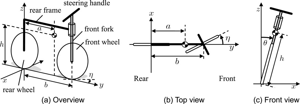
Figure 1. Simple bicycle model (Åström et al., 2005). (A) Overview, (B) top view and (C) front view. The steering angle is
3 Quadruped model
This section presents a quadruped robot model to investigate the applicability of the bicycle balance control mechanism, as described in Section 2. The balance control mechanism stabilizes posture by twisting the body frame through steering. Then, the proposed quadruped robot model implemented an actuated trunk DoF (Degree of Freedom) for steering and bicycle-inspired balance control. The following is a detailed description of the proposed model.
3.1 Mechanical structure
Figure 2 shows the mechanical structure of the quadruped robot model. The robot model comprises a front fork, rear frame, and four legs with a pantograph mechanism. The legs are connected to the front fork and rear frame. The front fork and the rear frame are perpendicularly connected with a trunk joint serving as a steering joint. The trunk joint rotation makes the front legs rotate in the axis of the trunk joint, as shown in Figure 2B. The inclined front fork, adjusted by
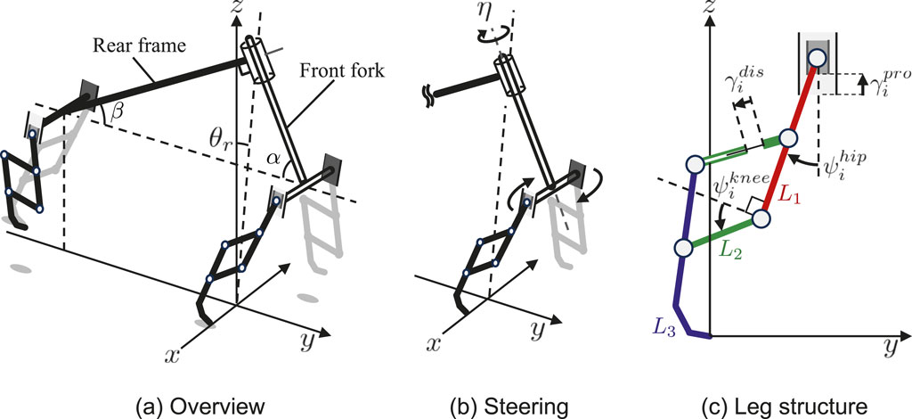
Figure 2. Mechanical structure of the quadruped model. (A) Overview (B) Steering mechanism that controls the trunk DoF in the yaw direction (C) Pantographic leg structure has four DoF: two actuated rotary joints at the hip and knee and two passive prismatic joints at the hip and pantograph.
The leg structure has a pantograph mechanism with four DoF, as shown in Figure 2C. The hip joint is an actuated rotary joint, which swings the leg in the anterior and posterior directions. The knee joint is an actuated rotary joint, which flexes and extends the leg with a pantograph mechanism. The two prismatic joints at the hip and the pantograph are passive spring dampers acting as suspensions.
3.2 Balance control
Drawing inspiration from the bicycle balance control, as described in Equation 2, we designed a balance control steering the trunk DoF angle
where
3.3 Leg control
The leg actuators are controlled by PD control and make the foot tip draw the target foot trajectory, as shown in Figure 3. The trajectory was designed to emulate the cheetah’s high-speed locomotion pattern (Zhang et al., 2022). Key characteristics include the initiation of backward leg movement during the swing phase and the considerable clearance. The frequency is controlled by phase oscillators implemented in each leg. The oscillator phase
where
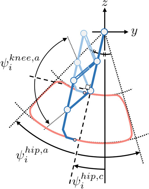
Figure 3. Leg trajectory. The deep and light blue legs represent the states of maximum and minimum extensions, respectively. The red line draws the leg trajectory. The roundness of the corners of the trajectory is determined by the constant
4 Simulation results
We conducted three experiments to evaluate the proposed model in the Open Dynamics Engine (Smith, 2005), a three-dimensional physical simulator. The first experiment investigated the running stability in multiple gaits, considering the differences between legged and wheeled locomotion. The second experiment investigated the robustness against disturbance. The third experiment investigated the turning performance.
All experiments were conducted on flat terrain, and the model parameters are listed in Tables 1, 2. The robot size and weight were determined somewhere between a typical quadruped robot and a bicycle, considering the effect of centrifugal forces contributing to stability. The robot size references that of a child’s bicycle and the weight references that of an actual quadruped robot (Unitree Go11), and both are adjusted iteratively throughout the simulation experiments. Based on the mechanical parameters, the control parameters were determined as physically plausible values through a trial-and-error process. The initial conditions were as follows: the velocity
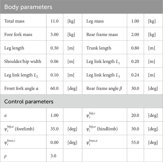
Table 1. Body and control parameters in simulation experiment.
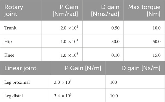
Table 2. Joint parameters in simulation experiment.
4.1 Locomotion sustainability with multiple gaits
Quadruped animals can move in various gaits (Alexander, 1984) unlike bicycles. The experiment investigated the gait variations of the robot model. The gait pattern is determined by the phase relationships between oscillators. We evaluated the locomotion performance for various gait patterns, which determine the left-right phase relationship
Here, when
The simulation results are shown in Figure 4. The success rate represents the proportion of sustainable gait shown within ten trials for each parameter set. There are two parameter areas showing a higher success rate, although the robot cannot achieve stable running within most of the parameter set. The first area,
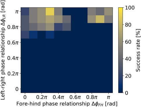
Figure 4. Locomotion sustainability with various gait patterns.
4.2 Robustness against disturbance
We conducted disturbance experiments that added the external force to the running robot model. The experimental duration is 7 [s], and the external force is 20 [N] in the
We observed the resulting behavior, as shown in Figure 5 and Supplementary Video S1. Figure 5A shows the time evolution of the roll angle
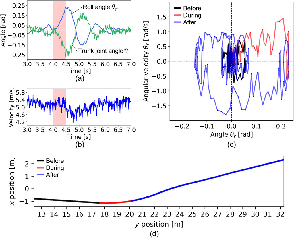
Figure 5. Disturbance experiment. The time evolution of (A) roll angle, trunk joint angle, and (B) velocity of the robot. The period (4.0–4.5 [s]) with the red color indicates the duration of the disturbance applied. (C) The relationship between the roll angle and angular velocity. The color of the lines indicates the time zone: black for before the disturbance, red for during, and blue for after. (D) Running trajectory on
Figure 5C shows the relationship between the roll angle
Figure 5D illustrates the robot’s running trajectory on the
Next, we investigated the relationship between the oscillator angular velocity
The simulation results are shown in Figure 6. The success rate represents the proportion of sustainable gaits demonstrated after the disturbance, based on ten trials for each parameter set. There is a tendency that higher
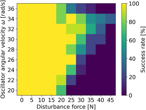
Figure 6. Relationship between the angular frequency of phase oscillator and robustness against disturbance.
4.3 Turning behavior
The steering handle is used to change the direction of movement of the bicycle, as well as to control balance. We conducted turning experiments to investigate the maneuverability of the proposed model. The turning behavior is generated by controlling the roll angel bias
We observed the turning behavior, as shown in Figure 7 and Supplementary Video S1. Figure 7A shows the time evolution of the roll angle

Figure 7. Turing experiment. The time evolutions of (A) roll angle
Next, we investigated the relationship between the turning performance and the parameter sets of the oscillator angular velocity
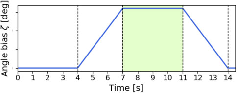
Figure 8. The time evolution of the roll angle bias
The simulation results are shown in Figure 9. Each color map shows velocity, turn radius, and average roll angle, respectively. The black area represents the trials in which falls occurred. The combination of lower
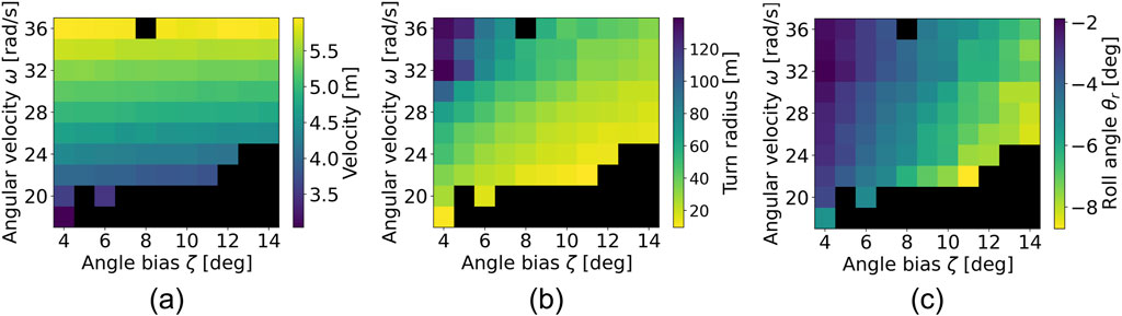
Figure 9. Color map of (A) velocity, (B) turn radius, and (C) roll angle. The black area indicates the trials in which falls occurred.
Figure 9A shows the velocity. The higher
5 Discussion
This study investigated the applicability of bicycle-inspired balance control in quadruped robot structures by introducing a yaw trunk joint as an alternative to a bicycle’s steering handle. The proposed model achieves stable high-speed locomotion (above 5 [m/s]) with robustness against external disturbances around 20 [N], along with maneuverability that allows for directional changes with only slight speed reduction, as shown in Figures 5–9. These results highlight the integration of bicycle balance control within a quadruped robot structure, demonstrating its feasibility for enhancing quadruped mobility. Unlike wheeled-legged robots (Bjelonic et al., 2022), which incorporate wheels into end effectors to enable both efficient locomotion and rough terrain adaptability, this study integrates wheeled-system features into the body frame. Whereas wheeled-legged designs typically require four additional degrees of freedom at the foot tips, our model requires only a single degree of freedom at the trunk, close to the center of mass, offering simpler implementation. This approach underscores the effectiveness of drawing inspiration from wheeled systems to improve quadruped agility without needing actual wheels.
Using centrifugal force through trunk movements for balance and turning aligns with locomotion strategies observed in quadruped animals (Kuznetsov et al., 2017; Wilson et al., 2013). Although previous studies introduced trunk joints in quadruped robots to enhance turning (Weinmeister et al., 2015; Wei et al., 2019; Lian et al., 2023; Wang et al., 2024), they did not account for the centrifugal effects that animals experience during sharp turns, nor did they demonstrate lean-in maneuvers. By explicitly demonstrating how centrifugal force aids balance control, this study contributes a novel insight into quadruped locomotion dynamics. Further exploration using the proposed model may enhance our understanding of animal high-speed motor control.
The proposed model is most effective in gaits resembling walking and trotting (Figure 4), where one front and one hind leg consistently maintain ground contact, similar to a bicycle’s continuous wheel-ground contact. However, the model struggles to achieve stable running in gaits like bounding and galloping, where the left-right phase relationship is closer to zero, typical of the fastest animal locomotion (Alexander, 1984). This limitation suggests that the model may only support a subset of animal gait patterns. Future work will develop additional control methods to enable gait patterns, including bounding and galloping, improving mobility and potentially contributing to our understanding of animal motor control.
Simulation results (Figures 5–9) indicate that centrifugal force contributes to both robustness against external forces and enhanced maneuverability. This approach, emphasizing the inherent dynamics of the model, is termed dynamics-based control (Osuka, 2001) in contrast to model-based control. For instance, passive dynamic walkers (McGeer, 1990) achieve natural gait using gravity alone, stabilized by implicit feedback structures derived from mechanical system (Sugimoto and Osuka, 2005). Our model similarly uses centrifugal force to simplify balance control, enhancing robustness without explicitly controlling roll posture. While conventional dynamics-based control relies on gravity, our approach demonstrates that centrifugal force can form the basis of a dynamics-based control strategy, providing insights into universal principles for dynamics-based control design in non-linear systems.
Future work should focus on further verification and investigation of the proposed model. First, conducting a theoretical analysis using Lyapunov methods, as well as comparisons with model-based and learning-based approaches, could help clarify the advantages of our model and establish a methodology for designing parameter sets, such as the roll angle bias
Data availability statement
The original contributions presented in the study are included in the article/Supplementary Material, further inquiries can be directed to the corresponding author.
Author contributions
SH: Conceptualization, Data curation, Formal Analysis, Funding acquisition, Investigation, Methodology, Project administration, Resources, Software, Validation, Visualization, Writing–original draft, Writing–review and editing. SS: Data curation, Formal Analysis, Methodology, Project administration, Resources, Validation, Writing–review and editing. AF: Data curation, Formal Analysis, Funding acquisition, Methodology, Project administration, Resources, Software, Validation, Writing–review and editing. TK: Data curation, Formal Analysis, Methodology, Project administration, Resources, Validation, Writing–review and editing. AI: Data curation, Formal Analysis, Methodology, Project administration, Resources, Supervision, Validation, Writing–review and editing.
Funding
The author(s) declare that financial support was received for the research, authorship, and/or publication of this article. This work was supported by the JSPS KAKENHI (Grant Number JP22KJ0320, JP22KJ2098, JP23K22700, and JP24H00294).
Acknowledgments
The authors would like to thank Dr. Kotaro Yasui, Dr. Hayato Amaike, Tomoyuki Baba, and Atsushi Norita of Tohoku University for their helpful suggestions.
Conflict of interest
The authors declare that the research was conducted in the absence of any commercial or financial relationships that could be construed as a potential conflict of interest.
The author(s) declared that they were an editorial board member of Frontiers, at the time of submission. This had no impact on the peer review process and the final decision.
Publisher’s note
All claims expressed in this article are solely those of the authors and do not necessarily represent those of their affiliated organizations, or those of the publisher, the editors and the reviewers. Any product that may be evaluated in this article, or claim that may be made by its manufacturer, is not guaranteed or endorsed by the publisher.
Supplementary material
The Supplementary Material for this article can be found online at: https://www.frontiersin.org/articles/10.3389/frobt.2024.1473628/full#supplementary-material
Footnotes
References
Alexander, R. M. (1984). The gaits of bipedal and quadrupedal animals. Int. J. Robotics Res. 3, 49–59. doi:10.1177/027836498400300205
Ali, Z. A., Wang, D., Safwan, M., Jiang, W., and Shafiq, M. (2016). Trajectory tracking of a nonholonomic wheeleed mobile robot using hybrid controller. Int. J. Model. Optim. 6, 136–141. doi:10.7763/ijmo.2016.v6.518
Åström, K. J., Klein, R. E., and Lennartsson, A. (2005). Bicycle dynamics and control: adapted bicycles for education and research. IEEE Control Syst. Mag. 25, 26–47. doi:10.1109/MCS.2005.1499389
Bellegarda, G., van Teeffelen, K., and Byl, K. (2018). “Design and evaluation of skating motions for a dexterous quadruped,” in 2018 IEEE international conference on Robotics and automation (ICRA) (IEEE), 1703–1709.
Bjelonic, M., Bellicoso, C. D., de Viragh, Y., Sako, D., Tresoldi, F. D., Jenelten, F., et al. (2019). Keep rolling’—whole-body motion control and planning for wheeled quadrupedal robots. IEEE Robotics Automation Lett. 4, 2116–2123. doi:10.1109/lra.2019.2899750
Bjelonic, M., Grandia, R., Harley, O., Galliard, C., Zimmermann, S., and Hutter, M. (2021). “Whole-body mc and online gait sequence generation for wheeled-legged robots,” in 2021 IEEE/RSJ international conference on intelligent robots and systems (IROS) (IEEE), 8388–8395.
Bjelonic, M., Klemm, V., Lee, J., and Hutter, M. (2022). “A survey of wheeled-legged robots,” in Climbing and walking robots conference (Springer), 83–94.
Endo, G., and Hirose, S. (2012). Study on roller-walker—improvement of locomotive efficiency of quadruped robots by passive wheels. Adv. Robot. 26, 969–988. doi:10.1163/156855312x633066
Hirose, S., and Takeuchi, H. (1996). “Study on roller-walk (basic characteristics and its control),” in Proceedings of IEEE international Conference on Robotics and automation (IEEE), 4, 3265–3270. doi:10.1109/robot.1996.509210
Klamt, T., and Behnke, S. (2017). “Anytime hybrid driving-stepping locomotion planning,” in 2017 IEEE/RSJ international conference on intelligent robots and systems (IROS) (IEEE), 4444–4451.
Kooijman, J. D. G., Meijaard, J. P., M, J., Papadopoulos, A. R., and Schwab, A. L. (2011). A bicycle can be self-stable without gyroscopic or caster effects. Science 332, 339–342. doi:10.1126/science.1201959
Kuznetsov, A., Luchkina, O., Panyutina, A., and Kryukova, N. (2017). Observations on escape runs in wild european hare as a basis for the mechanical concept of extreme cornering with special inference of a role of the peculiar subclavian muscle. Mamm. Biol. 84, 61–72. doi:10.1016/j.mambio.2017.01.003
Lian, Y., Wang, T., Ingham, J., Post, M. A., and Tyrrell, A. (2023). “Cpg-based locomotion control of a quadruped robot with an active spine,” in Annual conference towards autonomous robotic systems (Springer), 177–189.
McGeer, T. (1990). Passive dynamic walking. Int. J. robotics Res. 9, 62–82. doi:10.1177/027836499000900206
Osuka, K. (2001). Dynamics based control of mechanical systems. 2001 IEEE/ASME Int. Conf. Adv. Intelligent Mechatronics. Proc. (Cat. No.01TH8556) 1, 566–570. doi:10.1109/AIM.2001.936526
Sugimoto, Y., and Osuka, K. (2005). “Stability analysis of passive-dynamic-walking focusing on the inner structure of poincare map,” in ICAR’05. Proceedings., 12th international conference on advanced robotics, 2005 (IEEE), 236–241.
Wang, R., Xiao, H., Quan, X., Gao, J., Fukuda, T., and Shi, Q. (2024). Bioinspired soft spine enables small-scale robotic rat to conquer challenging environments. Soft Robot. 11, 70–84. doi:10.1089/soro.2022.0220
Wei, Z. L., Song, G., Sun, H., Qi, Q., Gao, Y., and Qiao, G. (2019). Turning strategies for the bounding quadruped robot with an active spine. Ind. Robot. 45, 657–668. doi:10.1108/IR-06-2018-0119
Weinmeister, K., Eckert, P., Witte, H., and Ijspeert, A. J. (2015). “Cheetah-cub-s: steering of a quadruped robot using trunk motion,” in 2015 IEEE international symposium on safety, security, and rescue robotics (SSRR), 1–6. doi:10.1109/SSRR.2015.7443021
Wilson, A. M., Lowe, J., Roskilly, K., Hudson, P. E., Golabek, K., and McNutt, J. (2013). Locomotion dynamics of hunting in wild cheetahs. Nature 498, 185–189. doi:10.1038/nature12295
Yongbin, J., Xianwei, L., Yecheng, S., Hongtao, W., and Wei, Y. (2022). High-speed quadrupedal locomotion by imitation-relaxation reinforcement learning. Nat. Mach. Intell. 4, 1–11. doi:10.1038/s42256-022-00576-3
Keywords: quadruped robot, model-free dynamic balance control, high-speed running, high-speed turning, bicycle-inspired control
Citation: Hattori S, Suzuki S, Fukuhara A, Kano T and Ishiguro A (2025) Bicycle-inspired simple balance control method for quadruped robots in high-speed running. Front. Robot. AI 11:1473628. doi: 10.3389/frobt.2024.1473628
Received: 31 July 2024; Accepted: 09 December 2024;
Published: 06 January 2025.
Edited by:
Ting Zou, Memorial University of Newfoundland, CanadaReviewed by:
Xiangxiao Liu, Swiss Federal Institute of Technology Lausanne, SwitzerlandZain Anwar Ali, Sir Syed University of Engineering and Technology, Pakistan
Copyright © 2025 Hattori, Suzuki , Fukuhara , Kano and Ishiguro . This is an open-access article distributed under the terms of the Creative Commons Attribution License (CC BY). The use, distribution or reproduction in other forums is permitted, provided the original author(s) and the copyright owner(s) are credited and that the original publication in this journal is cited, in accordance with accepted academic practice. No use, distribution or reproduction is permitted which does not comply with these terms.
*Correspondence: Shura Suzuki , c2h1cmEuc3V6dWtpLmM2QHRvaG9rdS5hYy5qcA==