- Centre for Autonomous and Cyber-Physical Systems, Faculty of Engineering and Applied Sciences, Cranfield University, Cranfield, United Kingdom
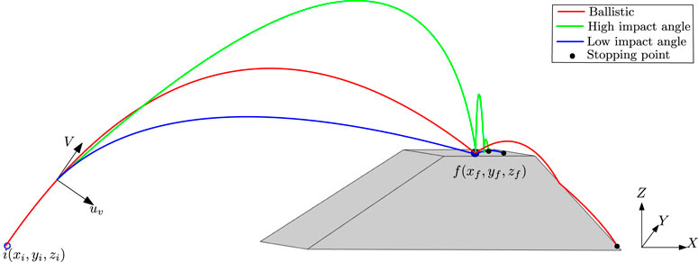
This paper presents a novel optimal trajectory-shaping control concept for a planetary hopping robot. The hopping robot suffers from uncontrolled in-flight and undesired after-landing motions, leading to a position drift at landing. The proposed concept thrives on the Generalized Vector Explicit (GENEX) guidance, which can generate and shape the optimal trajectory and satisfy the end-point constraints like the impact angle of the velocity vector. The proposed concept is used for a thruster-based hopping robot, which achieves a range of impact angles, reduces the position drift at landing due to the undesired in-flight and after-landing motions, and handles the error in initial hopping angles. The proposed approach’s conceptual realization is illustrated by lateral acceleration generated using thruster orientation control. Extensive simulations are carried out on horizontal and sloped surfaces with different initial and impact angle conditions to demonstrate the effect of impact angle on the position drift error and the viability of the proposed approach.
1 Introduction
Planetary robots (rovers) play a vital role in planetary surface exploration by gathering terrain information. Wheeled rovers can carry heavy payloads (e.g., scientific instruments, sensors, etc.) and are widely used in planetary exploration. However, they navigate at very low speeds (10 to
Typically, three design approaches, namely, strike or spring-based, internal flywheel-based, and thruster-based, are proposed to achieve the hopping. The strike or spring-based robots (Burdick and Fiorini, 2003) are the first designs that follow a ballistic trajectory. This robot’s current state-of-the-art uses work manipulation to achieve a jump over
Focusing on the hopping trajectory shaping, the initial launching errors, the uncontrolled ballistic phase, and undesired after-landing motions (e.g., bouncing, tumbling, slipping, etc.) take the hopping robot away from the desired landing site and might be in forbidden zones. Two possible solutions were proposed in the literature to overcome the after-landing motions. Considering the known surface properties, the first type of solution defines feasible take-off and landing cones and generates feasible hopping trajectories satisfying the defined cone constraints (Campana and Laumond, 2016; Upadhyay and Aguiar, 2020). By doing so, the slipping and bounded impact speed and terrain avoidance constraints can be addressed; however, the bouncing and tumbling motions cannot be controlled. Hence, this solution may be limited to terrestrial robots with instantaneous hopping capabilities (Haldane et al., 2017). Moreover, the take-off and landing cone constraints are coupled and may lead to non-existence of solutions. The second category of solutions uses internal flywheels to change the robot’s attitude in flight such that the robot falls over its face, leading to reduced bouncing. Then, breaking was applied to reduce the robot velocity (Li et al., 2020). The performance of this approach depends on the accuracy of the landing surface information and landing site selection for the hopping robot. On the other hand, the initial launching errors and the uncontrolled ballistic phase were rarely addressed and realized by the probability distribution of random errors (Upadhyay and Aguiar, 2020; Hockman and Pavone, 2020; Liang et al., 2022) to provide a worst-case landing region for validation of solutions as mentioned earlier.
In Tonasso et al. (2024), a lunar drone with thrusters combines ballistic trajectory with hovering. Here, the authors analysed the average thrust, total thrust duration, and required propellant for three types of trajectories that are (i) ballistic, (ii) a constant altitude flight, and (iii) mixed ballistic and constant altitude flight, which shows a controlled landing. However, the trajectories were pre-planned, and no active inflight trajectory shaping control was exercised. The in-flight trajectory generation or shaping using guidance theory is a widely researched topic in missile guidance problems (Ohlmeyer and Phillips, 2006; Mondal and Padhi, 2018; Ryoo et al., 2005), which has the capability to change the impact angle (Ratnoo and Ghose, 2008; Kumar and Ghose, 2017) and hence the potential to address the hopping motion issues. However, this approach is scarce in the hopping robot literature, which will be the key focus of this work.
This work demonstrates that impact angle-based trajectory shaping is a potential solution to the accurate landing problems (initiated launching errors, uncontrolled ballistic phase, and undesired after-landing motions) of hopping robots. The key contributions of this work are as follows:
The remainder of the paper is as follows: the concerned problem is described in Section 2. The proposed method, including the basics of impact angle-based guidance, is presented in Section 3, followed by the conceptual realisation of the proposal for a thruster-based hopping robot in Section 4. Section 5 presents the simulation results, and the paper is concluded in Section 6.
2 Problem description
Consider a point-mass robot hopping from a given initial position
where
2.1 Bouncing motion characterization with surface interaction
With the given coefficient of restitution
2.2 Requirements
1. The trajectory should be optimal. It can be mentioned that since the robot needs to fire thrusters during flight to control the trajectory, the guidance commands must be generated in an optimal control framework to minimise energy spending.
2. The hopping robot needs to start and finish at specific locations (usually called waypoints). It is important to note that there are mentions about the attitude control of the hopping robot to land in a way such that the after-landing motion is minimised. However, there are requirements for maintaining a specific attitude, such as pointing the camera at a specific angle or orientation for exploration or taking pictures. Therefore, changing attitudes can interrupt such operations. A trajectory-shaping impact angle control strategy (angle orientation of velocity vector during landing) can solve the issue. Hence, the impact angle is a requirement.
3. The trajectory shaping guidance algorithm must be generated in real-time, so it should have a closed-form expression.
We assumed that all the system states are measurable. Also, we have not considered any sensor or measurement noises.
3 Method: Generalized Vector Explicit (GENEX) guidance based impact angle control approach
The Genex algorithm has optimality, closed-form solution, and real-time execution (Ohlmeyer and Phillips, 2006) and hence is investigated as a potential candidate for the defined problem requirements 2.1. It can be mentioned that GENEX is used mainly as a missile guidance algorithm (Mondal and Padhi, 2018; Mondal and Padhi, 2019), path planning and collision avoidance problem (Subies Hueso et al., 2023) In this study, we will use GENEX to shape the trajectory of the hopping robot. We have introduced the philosophy and implementation facts in this section.
3.1 Basics of generalized vector explicit guidance (GENEX)
In this section, we present an overview of the guidance algorithm GENEX in the context of the interception of a target which is adopted from Ohlmeyer and Phillips, 2006. GENEX is formulated in an optimal control framework. It can guide an interceptor missile to a predefined position in space (generally called Predicted Interception Point or PIP) with its velocity vector oriented at a specific angle relative to the target’s velocity vector (called Impact angle). The guidance command has a closed-form expression, is computationally inexpensive, and easily implementable (Ohlmeyer and Phillips, 2006; Mondal and Padhi, 2019).
Let the lateral separation between an initial and its final point (PIP) be
where,
Define the states as.
Where.
subject to the terminal conditions
or
where
The Hamiltonian is defined by the scalar function
where,
the minimum principle of Pontryagin states that the control
Applying the minimum principle to the system, we get the following.
And
Now define a fundamental matrix
Equations 4, 6 imply
where
The state equation may be rewritten as
Now consider the equation
Substituting (Equations 6, 8) in Equation 9 gives
Therefore, we can write
Now substitute (Equation 11) into (Equation 10) and integrate:
because
Since
Using
we obtain
The inverse of
The optimum control is given by
Let
Then
where.
Now define new gains:
Finally, the optimal control expression is given by
Similar control expressions are obtained in the inertial ‘
For simplicity, we will represent the control vector as
where
The schematic of an engagement geometry is shown in Figure 2A. The GENEX guidance guides the interceptor from an initial position
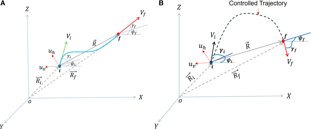
Figure 2. GENEX guides a vehicle from
The control thus obtained usually consists of acceleration components along the inertial frame. These are realised by transferring to other frames, such as body or velocity frames, using a rotation matrix. For example, to transfer from inertial to velocity frame (see Figure 2A), we may use the rotation matrix
Considering no thrust, i.e., no acceleration along the velocity direction, we can apply the acceleration (
3.2 Hopping trajectory using GENEX
The hopping scenario is similar to the missile guidance scenario. However, in the case of hopping, we do not consider the drag (see Section 2), and the final angle
4 A conceptual realization of GENEX based trajectory shaping control for a thruster- based hopping robot
The trajectory shaping of the hopping robot can be achieved by firing the thruster to produce lateral acceleration. Now, the question is how to produce the lateral acceleration for a hopping robot using the thruster. To answer this question, We will look into the thruster orientation control using gimbals and cable actuation of Spherical Tensegrity Robots (Kim et al., 2016). Here, the authors proposed thruster-based hopping, which is made feasible by the lightweight and compliant nature of the tensegrity structure. They also developed suitable controls for changing thruster orientation while initiating each hop (not during the flight). Three high-level approaches for adjusting the thruster direction during a hopping event were investigated, i.e., a) gimbaled nozzle thruster, b) gimbal-enclosed thruster system, and c) cable-actuated thruster system. They adjusted the thruster direction to initiate a hop in a specific direction. We can refer to the example of a cable-actuated thruster system, which is a possible method for controlling the orientation of the thruster. In this system, the thruster and the payload are connected to the ends of the tensegrity rods by fixed-length compliant cables. By changing the shape of the structure, orientation control can be achieved. Please refer to Fig. 8 in Section 4 of Kim et al. (2016) for a visual representation of this system. In Kim et al. (2016), the minimum and maximum angles (both elevation and azimuth) are achieved by cable actuation (inner, outer, and both); hence, the thruster can be oriented within these ranges.
4.1 Attitude and thruster orientation control
This study only considers the hopping motion confined to the vertical
Here, we focus on Figure 3A. The body axis (
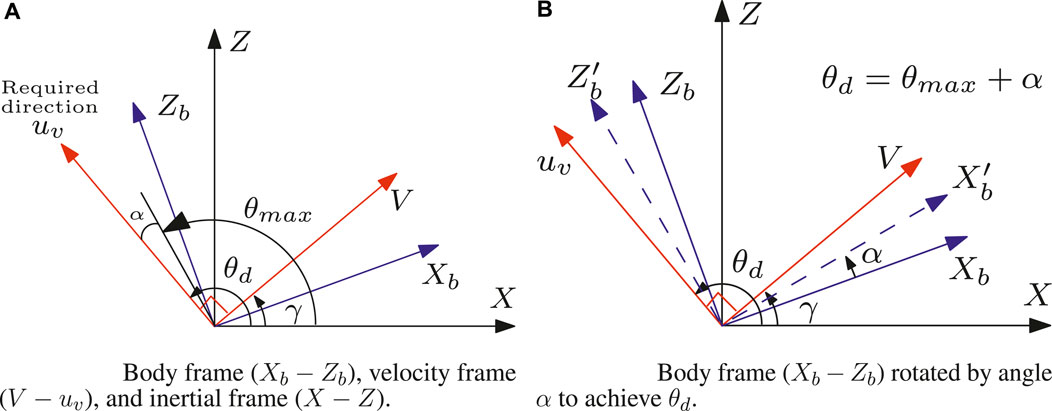
Figure 3. Different frames and their rotation to describe the thruster orientation of a point mass hopping robot when
Let us consider the body axis
5 Results and discussions
We have assumed that attitude control was performed using any existing technique, that is, to rotate the body axis at an angle
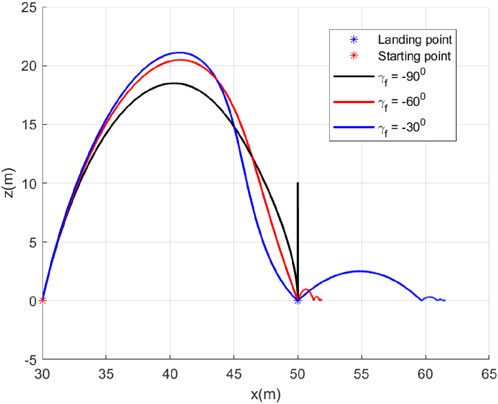
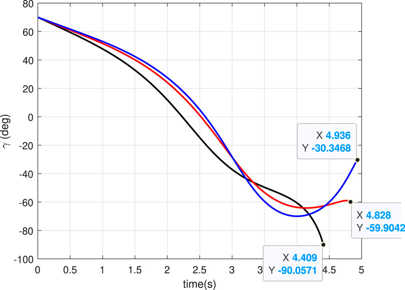
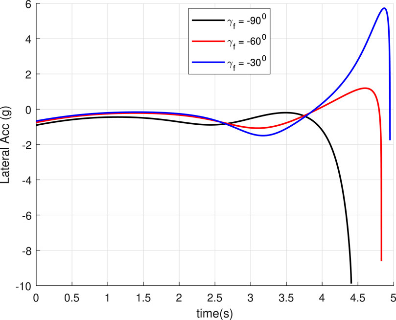
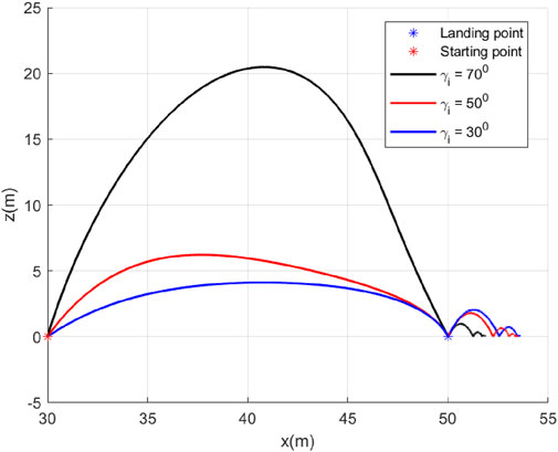
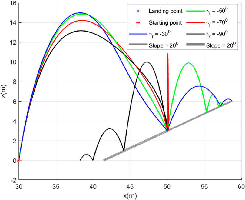
5.1 Case 1: Different
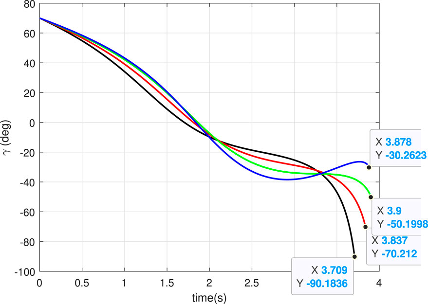
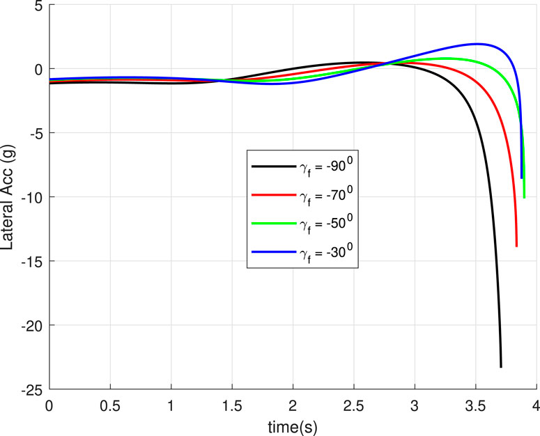
In this case, we consider a flat landing surface and the final landing angle
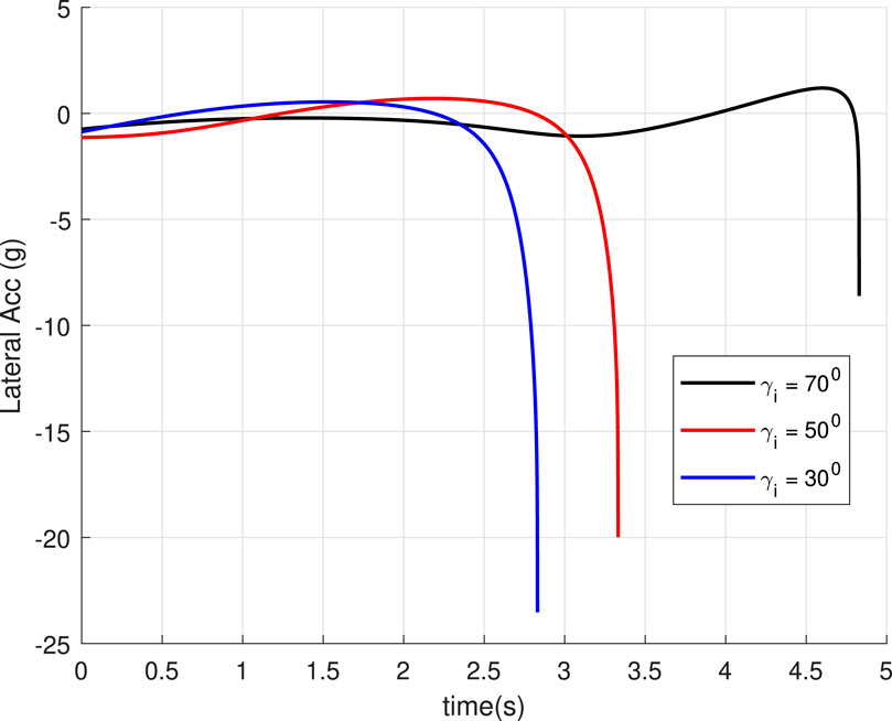
5.2 Case 2: Different
In this case, we will study the effect of varying the initial hopping angle
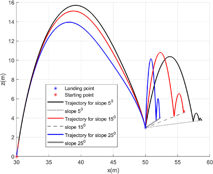
5.3 Case 3: Slope of landing surface varies
In this case, we will study the bouncing of the robot on surfaces with different inclination angles
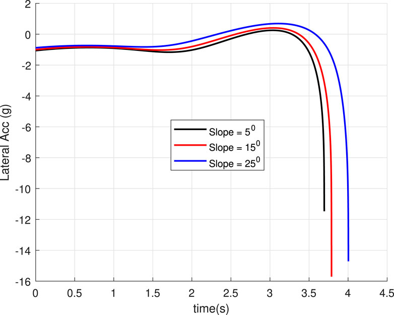
Figure 12. Lateral acceleration for the different inclination angles of the landing surface (Case 3).
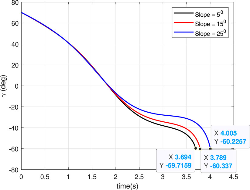
5.4 Case 4: Landing on same slope with different
We will study the bounce from a slope when the robot lands with different
6 Conclusion
We have proposed an optimal trajectory shaping control approach using GENEX for a thruster-based hopping robot. The algorithm can make the hopping robot achieve different impact angles for the same initial conditions, improving the landing accuracy. The trajectory shaping control can make the hopping robot land accurately at the landing position with a precalculated impact angle despite any initial hopping angle or velocity errors. Thus, the analysis of landing inaccuracy is relaxed. We have presented an example of the conceptual realization of the proposed approach that can be implemented on existing thruster-based hopping robot designs. The effectiveness of the proposed guidance is explained through a simulation study using various cases like horizontal and inclined landing surfaces with various initial final conditions. The results demonstrate the effect of landing angles on after-landing inaccuracy, which can be reduced by choosing the appropriate landing angle. The selection of the best landing angle for pinpointing, implementing realistic hopping robot models, and integration with a sequential multi-hopping trajectory generation approach are immediate works in the future. Another interesting future works are a study on the effect of attitude knowledge inaccuracies (such as biases and drift from onboard sensors) on the proposed approach and the integration of the proposed approach with an appropriate estimator to handle such inaccuracies are future works.
Data availability statement
The raw data supporting the conclusions of this article will be made available by the authors, without undue reservation.
Author contributions
SM: Conceptualization, Investigation, Methodology, Software, Validation, Writing–original draft, Writing–review and editing. SU: Conceptualization, Formal Analysis, Investigation, Validation, Writing–original draft, Writing–review and editing.
Funding
The author(s) declare that no financial support was received for the research, authorship, and/or publication of this article.
Conflict of interest
The authors declare that the research was conducted without any commercial or financial relationships that could be construed as a potential conflict of interest.
Publisher’s note
All claims expressed in this article are solely those of the authors and do not necessarily represent those of their affiliated organizations, or those of the publisher, the editors and the reviewers. Any product that may be evaluated in this article, or claim that may be made by its manufacturer, is not guaranteed or endorsed by the publisher.
References
Burdick, J., and Fiorini, P. (2003). Minimalist jumping robots for celestial exploration. Int. J. Robotics Res. 22, 653–674. doi:10.1177/02783649030227013
Campana, M., and Laumond, J. P. (2016). Ballistic motion planning. 2016-Novem, 1410–1416. doi:10.1109/IROS.2016.7759230
Ettlin, A., and Bleuler, H. (2006). “Rough-terrain robot motion planning based on obstacleness,” in 2006 9th International Conference on Control, Automation, Robotics and Vision, China, 5-8 Dec. 2006, 1–6. doi:10.1109/icarcv.2006.345116
Geromichalos, D., Azkarate, M., Tsardoulias, E., Gerdes, L., Petrou, L., and Perez Del Pulgar, C. (2020). Slam for autonomous planetary rovers with global localization. J. Field Robotics 37, 830–847. doi:10.1002/rob.21943
Haldane, D. W., Yim, J. K., and Fearing, R. S. (2017). “Repetitive extreme-acceleration (14-g) spatial jumping with salto-1p,” in IEEE/RSJ International Conference on Intelligent Robots and Systems (IROS), USA, 1-5 Oct. 2023, 3345–3351. doi:10.1109/IROS.2017.8206172
Hockman, B., and Pavone, M. (2020). “Stochastic motion planning for hopping rovers on small solar system bodies,” in Robotics research: the 18th international symposium ISRR (Germany: Springer), 877–893.
Hockman, B. J., Frick, A., Reid, R. G., Nesnas, I. A., and Pavone, M. (2017). Design, control, and experimentation of internally-actuated rovers for the exploration of low-gravity planetary bodies. J. Field Robotics 34, 5–24. doi:10.1002/rob.21656
Kim, K., Chen, L.-H., Cera, B., Daly, M., Zhu, E., Despois, J., et al. (2016). “Hopping and rolling locomotion with spherical tensegrity robots,” in 2016 IEEE/RSJ international conference on intelligent robots and systems (IROS), China, 9-14 Oct. 2016 (IEEE), 4369–4376.
Kumar, S. R., and Ghose, D. (2017). Three-dimensional impact angle guidance with coupled engagement dynamics. Proc. Institution Mech. Eng. Part G J. Aerosp. Eng. 231, 621–641. doi:10.1177/0954410016641442
Li, X., Sanyal, A. K., Warier, R. R., and Qiao, D. (2020). Landing of hopping rovers on irregularly-shaped small bodies using attitude control. Adv. Space Res. 65, 2674–2691. doi:10.1016/j.asr.2020.02.029
Liang, Z., Lv, C., Zhu, S., and Ge, D. (2022). Guidance for precision landing on asteroid using active hopping trajectory. Acta Astronaut. 198, 320–328. doi:10.1016/j.actaastro.2022.06.003
Mondal, S., and Padhi, R. (2018). Angle-constrained terminal guidance using quasi-spectral model predictive static programming. J. Guid. Control, Dyn. 41, 783–791. doi:10.2514/1.g002893
Mondal, S., and Padhi, R. (2019). Generalized explicit guidance with optimal time-to-go and realistic final velocity. Proc. Institution Mech. Eng. Part G J. Aerosp. Eng. 233, 4926–4942. doi:10.1177/0954410019834780
Ohlmeyer, E. J., and Phillips, C. A. (2006). Generalized vector explicit guidance. J. Guid. Control, Dyn. 29, 261–268. doi:10.2514/1.14956
Ratnoo, A., and Ghose, D. (2008). Impact angle constrained interception of stationary targets. J. Guid. Control, Dyn. 31, 1817–1822. doi:10.2514/1.37864
Ryoo, C.-K., Cho, H., and Tahk, M.-J. (2005). Optimal guidance laws with terminal impact angle constraint. J. Guid. Control, Dyn. 28, 724–732. doi:10.2514/1.8392
Subies Hueso, J., Mondal, S., Tsourdos, A., and Chadwick, A. (2023). Real-time collision avoidance trajectory planner using generalized vector explicit guidance. AIAA 2023-1734. doi:10.2514/6.2023-1734
Tonasso, R., Tataru, D., Rauch, H., Pozsgay, V., Pfeiffer, T., Uythoven, E., et al. (2024). A lunar reconnaissance drone for cooperative exploration and high-resolution mapping of extreme locations. Acta Astronaut. 218, 1–17. doi:10.1016/j.actaastro.2024.02.006
Tzanetos, T., Bapst, J., Kubiak, G., Tosi, L. P., Sirlin, S., Brockers, R., et al. (2022). “Future of mars rotorcraft - mars science helicopter,” in 2022 IEEE Aerospace Conference (AERO), China, 5-12 March 2022, 1–16. doi:10.1109/AERO53065.2022.9843501
Keywords: hopping robot, trajectory shaping control, generalized vector explicit (GENEX) guidance, planetary exploration, space robotics
Citation: Mondal S and Upadhyay S (2024) Trajectory shaping guidance for impact angle control of planetary hopping robots. Front. Robot. AI 11:1452997. doi: 10.3389/frobt.2024.1452997
Received: 21 June 2024; Accepted: 07 October 2024;
Published: 11 November 2024.
Edited by:
Morad Nazari, Embry–Riddle Aeronautical University, United StatesReviewed by:
Barış Can Yalçın, University of Luxembourg, LuxembourgAntonio Genova, Sapienza University of Rome, Italy
Copyright © 2024 Mondal and Upadhyay. This is an open-access article distributed under the terms of the Creative Commons Attribution License (CC BY). The use, distribution or reproduction in other forums is permitted, provided the original author(s) and the copyright owner(s) are credited and that the original publication in this journal is cited, in accordance with accepted academic practice. No use, distribution or reproduction is permitted which does not comply with these terms.
*Correspondence: Sabyasachi Mondal, c2FieWFzYWNoaS5tb25kYWxAY3JhbmZpZWxkLmFjLnVr
 Sabyasachi Mondal
 Saurabh Upadhyay