 Yejia Zeng
 Zukun Lu
 Yuchen Xie1,2
 Binbin Ren
- 1College of Electronic Science and Technology, National University of Defense Technology, Changsha, China
- 2National Key Laboratory for Positioning, Navigation and Timing Technology, Changsha, China
- 3Hunan Xinghe Electronics Co. LTD., Changsha, China
Attitude determination of rotary-wing unmanned aerial vehicles (RUAVs) is crucial for grasping their motion state and is a necessary condition to ensure the correct execution of flight missions. With the continuous development and the constant enhancement of measurement accuracy related to the Global Navigation Satellite System (GNSS), attitude determination based on GNSS have become the mainstream high-precision attitude measurement approach. This paper mainly discusses the relevant theories of using GNSS for RUAV’s attitude determination, and introduces the relevent key aspects that determine attitude accuracy in the attitude resolution process, such as integer ambiguity fixing, attitude solution algorithms, and integrated attitude measurement. It especially elaborates on the challenges that faced to be solved for current RUAVs to use the GNSS system for real-time and guarded attitude measurement.
1 Introduction
Unmanned Aerial Vehicles (UAVs), characterized by their high controllability, low production costs, and the separation of human operators from the vehicle, are widely used across various civilian and military domains. In the civilian sector, UAVs can be employed for applications such as topographic surveys, disaster detection, power line inspections, search and rescue operations, target tracking, and the establishment of wireless networks [1–4]. In the military sphere, their low cost, high mobility, compact size, and difficulty to detect make them ideal for battlefield reconnaissance, supply transportation, information confrontation, communication relay, and firepower engagement [5]. Conflicts such as those in Syria, the Nagorno-Karabakh region, and the Russia-Ukraine war have seen the emergence of various types of UAVs, including integrated reconnaissance-strike, surveillance, and suicide attack drones [6–8].
Rotor Unmanned Aerial Vehicles (RUAVs), a type of UAV, are relatively small in size and rely on the rotation of multiple wing propellers to lift and move. They possess the capability for vertical takeoff and landing and omnidirectional flight, exhibiting higher maneuverability and flexibility at a negligible cost compared to fixed-wing UAVs [9]. As shown in Figure 1, the earliest RUAVs appeared in 1907 with the “Gyroplane No.1″designed by Professors Jacques Breguet and “Oehmichen No.2″invented by Etienne Oehmichen [10]. With the advent of the 21st century, the development level of rotor UAVs has been greatly enhanced by the invention of new controllers and sensors [11]. Stanford University designed the multi-autonomous platform control testbed STARMAC, capable of precise flight control and equipped with some obstacle avoidance capabilities [12, 13]. The German classic multi-rotor UAV, MD4-1000, equipped with a camera gimbal, can achieve autonomous navigation using image capture. In recent years, Dajiang UAV has rapidly occupied the RUAV Market, typical products like the Inspire 1, Mavic 2, and Phantom 4 can enhance obstacle avoidance capabilities using a visual processing unit [14].
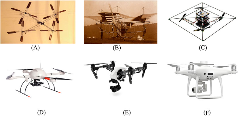
Figure 1. Classic drone. (A) “Gyroplane No.1”. (B) “Oehmichen No.2”. (C) “STARMAC-2”. (D) “MD4-1000”. (E) “Inspire 1”. (F) “Phantom 4”.
The flight attitude information of a RUAV is a crucial parameter for describing its motion state, equally important as its position and velocity information. Attitude angles can provide data support for attitude control in the flight control system, assist the flight control system in making adjustments, ensuring that the drone maintains balance during flight, which is crucial for flight safety [15]; In the context of multi-drone systems or collaborative missions, accurate attitude measurement is crucial for maintaining formation flight and coordinated operations [16]; Attitude also helps drones avoid collisions and obstacles, especially when visual obstacle avoidance systems are combined with data from attitude sensors. The angular information obtained from attitude measurements assists the flight control system in calculating the necessary adjustments for obstacle avoidance [17]; The heading and attitude information of a UAV, is also a powerful basis for the UAV to counteract directional interference [18].
Initially, the attitude determination of the carrier relied on the Inertial Navigation System (INS), which, as a navigation system capable of independently outputting positioning and attitude, has the characteristics of working independently without the need for external equipment. It can effectively resist external interference, offering good autonomy, concealment, and continuity [19]. However, as the working time of INS increases, the measurement errors caused by mechanical devices will accumulate over time, leading to a decrease in measurement accuracy [20]. High-precision inertial navigation equipment is usually bulky and costly, making it unsuitable for small and low-cost RUAVs.
The Global Navigation Satellite System (GNSS), is fully applied in the fields of navigation, timekeeping, positioning, and attitude determination due to its all-weather, global, high-precision, and high-real-time characteristics. It has the advantages of low cost, small size, low power consumption, short initialization time, and no error accumulation effect [21]. Small RUAVs widely adopt satellite navigation to obtain state information such as position, velocity, and attitude [22]. The carrier phase differential as an observation method helps to minimize the impact of clock differences and atmospheric delays under short baselines, and when obtaining the right integer ambiguity, the phase observation is two orders of magnitude more accurate than pseudo-range observation, which helps UAVs achieve high-precision attitude determination [23]. Attitude measurement uses the changes in the short baseline in different coordinate systems to obtain the attitude angle, involving a series of key issues such as the flight integer ambiguity and attitude angle solution algorithm [24, 25].
The attitude determination of RUAVs is a critical step in grasping their motion state information and a necessary condition to ensure their own safety. Therefore, focusing on the UAV attitude determination based on GNSS, this paper elaborates on the relevant theories of attitude determination in recent years, concentrating on key technologies in the attitude determination process, such as the determination of integer ambiguity and attitude resolution algorithms. At the same time, it analyzes the security challenges faced when using GNSS for UAV attitude determination in complex electromagnetic environments.
2 Current research status of RUAV attitude measurement based on GNSS
2.1 Existing GNSS attitude measurement products
The application of GNSS was initially for precise positioning and navigation. As the navigation system evolved and the use of carrier phase differential observation became more mature, its high-precision measurement capabilities gradually extended to the field of attitude measurement [26, 27]. In 1978, Coumselma [28] proposed the use of GPS carrier phase differential measurement for attitude determination, designing a full link attitude measurement system from the satellite to the receiver. Hermann [29] tested the software receiver TI-AGR for attitude measurement, proving that GPS signals can achieve millimeter-level attitude measurement on long baselines. Trimble Navigation Limited used a three-antenna two-baseline attitude determination device on a U.S. Navy cruiser for dynamic determination experiments, verifying that GPS can provide attitude information for low-dynamic motion carriers [30]. Entering the 21st century, more mature GNSS-based attitude measurement systems have emerged abroad, such as the 3DF system by Ashtech [31], the Tans Vector system by Trimble [32], and the JNSGyro-2T and JNSGyro-4T systems by Javad [33]; the Beeline system by NovAtel [34].
Currently, the ZH6000A, developed by Zihang Electronic Technology, is a three-antenna GNSS full-attitude measurement and positioning GNSS-INS combined system, capable of precisely calculating attitude angles with an accuracy of 0.05° (4-meter baseline); meanwhile, the built-in IMU can perform real-time high-precision GNSS/INS combined solutions [35]. The SIN-INS3000 system, developed by Xi’an Sine Wave Measurement and Control Technology, utilizes a combination of GNSS and fiber optic inertial navigation to achieve a roll and pitch accuracy of 0.02° [36]. The GNSS/INS integrated navigation system, developed by Airic Co. Inertial Technology, provides continuous and high-precision information. Employing a dual-antenna GNSS module in conjunction with an INS system, the system offers combined attitude determination with roll and pitch accuracies of 0.01° and 0.004° post-processing, respectively. The heading accuracy can reach 0.05°, with post-processing accuracy achievable up to 0.01° [37].
There are also products that use multiple satellite navigation system signals for attitude measurement, such as the MTi-G-710 sensor, developed by Xsens [38], aided by INS and utilizing signals from navigation systems such as GLONASS and Beidou. It outputs GNSS-enhanced 3D orientation and is capable of achieving pitch, roll, and yaw angle accuracies of 0.2°, 0.3°, and 1.0°, respectively. The 3DM-GX5-GNSS/INS system, developed by MicroStrain Sensing Systems, utilizes global navigation satellite systems such as GPS and GLONASS to provide precise 3D attitude determination. By integrating GNSS data with INS data through an Extended Kalman Filter and a Complementary Kalman Filter, the system achieves roll and pitch angle accuracies of 0.25°, with a heading accuracy of 0.8° [39].
2.2 Unique aspects of RUAVs attitude determination
RUAVs, due to limitations of their own platform, are equipped with a limited number of receiver antennas, and the baseline length formed by the antennas is of the short-baseline type, which is different from the medium to long-baseline issues present in platforms like vehicles and ships (greater than 1 m) [40]. Attitude determination often benefits from longer baseline lengths. Therefore, the attitude determination of RUAVs differs from conventional circumstances, it is conducted under short-baseline conditions [41]. Besides, the limitation on the number of baselines due to the size constraints of their own platform is also a special issue that needs to be considered.
Secondly, during the flight of rotary-wing unmanned aerial vehicles, especially in swarm operations, when directional changes are flexible and diverse, and angular velocity changes are rapid, the refresh rate of satellite navigation measurements is low and cannot match the high-dynamic angle change requirements of the RUAVs. Therefore, it is common to combine the attitude determination with the inertial navigation system. However, due to the low-cost requirements of the UAVs themselves, the accuracy of low-cost inertial navigation devices is low, and there is an accumulation of errors that require correction by the satellite navigation system [15]. In addition to relying on satellite navigation signals for determination, it is also necessary to study the fusion data algorithms in integrated navigation to complement the advantages of satellite navigation and inertial navigation, thereby improving the precision of the measurements.
Since UAVs are often in complex electromagnetic environments, when using satellite navigation for positioning and attitude determination, the satellite navigation signals are relatively weak when reaching the ground, generally at −160dBW, and the navigation signal system is often semi-public. The rotary-wing unmanned aerial vehicle has a relatively low speed of movement, making it susceptible to jamming and spoofing interference [42]. At the same time, due to the load restrictions of rotary-wing UAVs, with limited anti-interference capabilities without the support of facilities such as null steering antenna, the accuracy of positioning and attitude determination results is seriously affected by interference, and the UAV’s own motion state faces safety issues. For example, during UAV swarm performances, unknown interference can lead to loss of control of the swarm [43]; To ensure the normal flight of UAVs in complex electromagnetic environments and ensure their survivability, it is necessary to considering the UAV’s anti-interference capabilities, which is the particularity of RUAV attitude measurement [44].
3 Knowledge of UAV attitude measurement
Using satellite navigation for attitude measurement, the accuracy of the attitude angles depends on factors such as observation quality, antenna configuration, and solving methods [39]. The attitude determination process using GNSS often involves two steps: coordinate conversion and baseline solution. Research is often conducted to improve the accuracy and reliability of attitude calculation [45]. Key points of which integer ambiguity determination and attitude angle solution attract numerous researchers to study [46–48].
3.1 Basic principles of attitude determination
During the flight of an RUAV, the flight control system continuously receives real-time position and heading information from sensors such as GNSS receivers and gyroscopes. It then calculates the yaw distance and heading control quantities based on remote control commands, causing the aircraft wings to rotate to varying degrees, thereby steering the UAV in the correct direction [1]. As shown in Figure 2, attitude determination using satellite navigation generally involves the relative changes in the positions of multiple antennas fixed on the carrier in different coordinate systems. Key points related to the carrier’s attitude include the description method of attitude angles, coordinate systems, and the transformation matrices between coordinate systems.
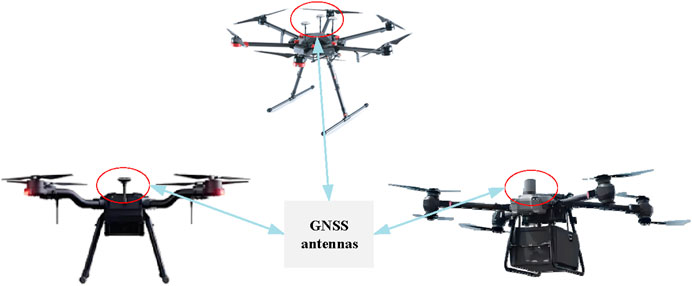
Figure 2. Common RUAV and navigation receiver antenna.
As shown in Table 1, there are three common ways to describe attitude angles: Euler angles, quaternions, and direction cosines, which can be converted from one to another [49, 50]. In UAV attitude measurement, the Euler angle method is often used, that is, heading angle, pitch angle, and roll angle, which can intuitively reflect the attitude information of the carrier.
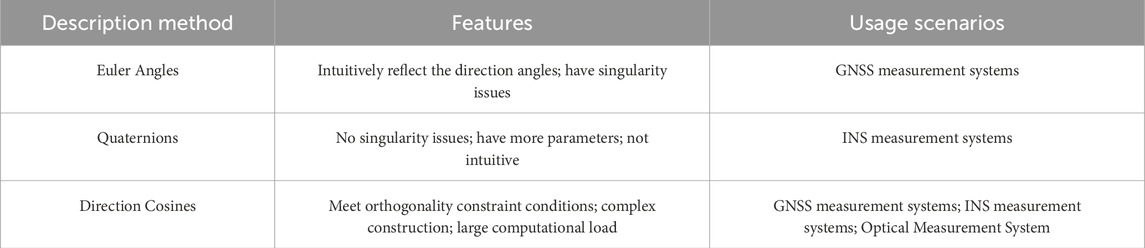
Table 1. Common description methods for attitude angles.
In addition, attitude measurement often involves three coordinate systems, as shown in Figure 3, namely the Earth-centered Earth-fixed coordinate system (ECEF), the local horizontal coordinate system (LHCS), and the vehicle coordinate system (VCS). The ECEF coordinate system, as shown in Figure 3A, rotates with the Earth and is used to describe the position calculated according to navigation messages; the local horizontal coordinate system in Figure 3B, has its origin at the center of the carrier and describes the coordinates of a point in space relative to a selected reference point, also known as the East North Up (ENU) coordinate system; the vehicle coordinate system is fixed on the carrier and changes with the carrier’s motion and attitude, which is shown in Figure 3C. The Y-axis generally points in the direction of the carrier’s heading, the Z-axis points towards the zenith direction, and the X-axis, together with the X-axis and Z-axis, forms a right-handed coordinate system.
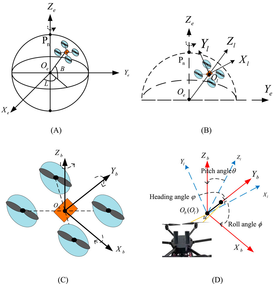
Figure 3. Coordinate system used for attitude determination. (A) Earth-centered earth-fixed coordinate system. (B) Local coordinate system. (C) Body coordinate system. (D) Rotation diagram.
In Figure 3D, taking a single baseline formed by dual antennas as an example, antennas u and r fixed on the carrier constuct a baseline, whose coordinates in VCS are determined when the antennas are installed, that is
A. From ECEF to LHCS:
where
B. From LHCS to VCS:
The common rotation sequence of the coordinate systems, according to the right-hand rule, involves rotating the local horizontal coordinate system successively around the Z-axis by angle
where
Equation 4 represents the transformation of the baseline using Equation 3.
In Equation 3, the attitude angle information is contained in the rotation matrix. By solving Equation 4, the rotation matrix is obtained, and then the attitude angle is obtained. At least two non-collinear baselines are required to solve for the complete set of angles
3.2 GNSS-based observation model
GNSS attitude measurement systems can be categorized based on the number of antennas deployed into single-antenna measurement, single-baseline (dual-antenna) measurement, and multi-baseline measurement [51, 52], as shown in Figure 4.
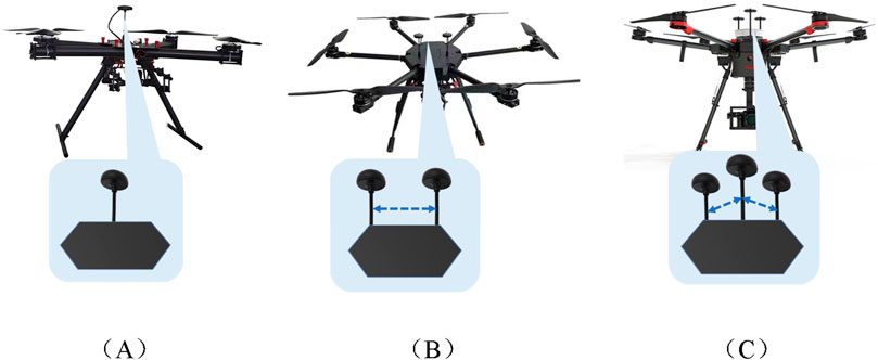
Figure 4. Schematic diagram of UAV navigation antenna and baseline. (A)Single-antenna. (B)Dual-antenna. (C)Multi-antenna.
As shown in Figure 4A, single-antenna attitude measurement refers to an unmanned aerial vehicle (UAV) equipped with a single satellite navigation receiver antenna. The single antenna primarily relies on received signal strength for measurement, which has low precision. Multi-antenna attitude measurement refers to a UAV using two or more satellite navigation receiver antennas. Due to the size constraints of the UAV, the baseline length formed by the receiving antennas is generally less than 1 meter, belonging to the short-baseline category, which is different from the medium to long-baseline types formed by antenna arrangements on vehicles, where lengths typically range from 1.5 to 2 m [40]. The dual antenna constitutes a single baseline, as depicted in Figure 4B, which can only obtain limited attitude angle information [41], while three or more antennas form multiple baselines in Figure 4C. Table 2 lists the GNSS based attitude determination methods divided by the number of antennas or baselines, the principles and characteristics of each method, and typical application scenarios.
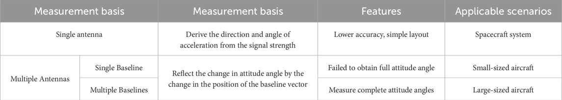
Table 2. GNSS attitude determination model.
In Table 2, it can be observed that while single-antenna measurement is simple to deploy and has the lowest cost, it relies on signal strength and thus has low and unreliable accuracy, especially considering the inherently low power of navigation signals upon ground reception. Multi-baseline measurement can provide redundant information and obtain complete attitude angle data, but it requires a larger number of antennas, leading to higher hardware costs [53]. For low-cost RUAVs, which already equipped with gyroscopes and other inertial navigation devices, dual-antenna systems although not providing complete attitude angle information, can be integrated with inertial navigation devices, achieving complete information acquisition while balancing hardware costs and information retrieval capabilities. Additionally, dual-antenna systems can implement RTK, enabling precise positioning of UAVs [54]. Therefore, current RUAVs primarily carry dual antennas for positioning and attitude determination under short-baseline conditions.
Regarding the selection of the observation model, since the precision of carrier phase observation is more than two orders of magnitude higher than that of pseudo-range observation, carrier phase differential methods are commonly used for attitude determination [55]. For the short baseline measurement of UAVs, the use of carrier phase differential technology can largely eliminate satellite and receiver clock differences and mitigate the propagation delays caused by the ionosphere and troposphere.
The carrier observation equation of the receiver for the satellite is shown in Equation 5
Where
The carrier phase differential method, based on the number of receivers and observed satellites, as shown in Figure 4, can be divided into single difference (SD), double difference (DD), and triple difference (TD), which can eliminate satellite clock differences, receiver clock differences, and integer ambiguities [56, 57].
In the three differential observation schematics shown in Figure 5, SD involves taking the difference between measurements of the same satellite by two receivers at the same observation time [58]. DD makes difference between two receivers for single difference observation of different satellites; TD involves differencing the double differences at two different times. Table 3 shows mathematical model of the common differential methods, which illustrates the observation equations, main error terms, ambiguities, and differential observation noise corresponding to the three types of differential methods [21].
Where,
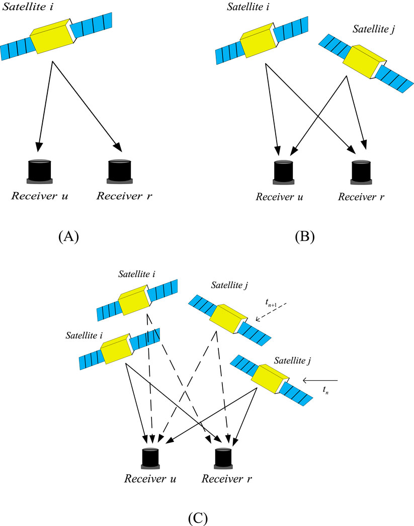
Figure 5. Schematic diagram of three differential observations. (A) Single difference observation. (B) Double difference observation. (C) Triple difference observation.
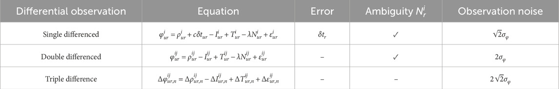
Table 3. Common differential methods.
From Table 3, it can be observed that SD completely eliminates satellite clock errors and approximately eliminates ionospheric and tropospheric delays when the two receivers are in close proximity. However, after single-differencing, receiver clock biases
As it is shown, although each time of differencing can further reduce the clock bias and other errors, the root mean square of the measurement noise will also increase to the
3.3 Analysis of influence factors of attitude determination
Based on the content of the previous two sections, attitude determination using satellite navigation involves coordinate transformations and the solution of navigation signal observations. From Equations 1, 4, it can be seen that to solve for the attitude angles, the essence is to solve for the baseline vector. Since the UAV’s receiving antennas form a short baseline, the ionospheric delay errors and tropospheric delay errors have already been differentially eliminated in the single-difference process. The observation equations shown in Table 3 are then converted to be represented by the baseline vector, as shown in Table 4.
Where
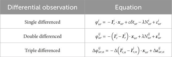
Table 4. Observation equation expressed by baseline.
In the attitude determination of RUAVs, as discussed in the previous sections, attitude solutions can be divided into observation solutions and coordinate solutions. When using carrier phase observations for solving, the choice of observation method will affect the factors influencing the baseline vector solution process differently. SD observations are affected by receiver clock biases, integer ambiguities, and observation noise; DD observations are affected by integer ambiguities and observation noise; TD observations are only affected by observation noise. Receiver clock biases can cause phase misalignment, integer ambiguities can lead to errors in the distance measurement between the receiver and the satellite, directly affecting the reliability of the baseline vector; observation noise affects the accuracy of the baseline vector.
In coordinate calculation, it can be observed that the coordinate transformation in Equation 1 requires the longitude and latitude obtained from the receiver’s positioning solution, meaning that the accuracy of positioning affects the accuracy of the baseline coordinate transformation. Additionally, in Table 4, the direction of the receiver’s observations to the satellites also affects the accuracy of the baseline vector solution. Furthermore, since it is necessary to solve the rotation matrix in Equation 4, when using Euler angles, singularity issues arise during high-dynamic complex motions of the UAV, making solutions unattainable. In such cases, quaternions must be used for representation, but this increases computational complexity. Therefore, the method of attitude representation also affects the solution of attitude angles [59].
The redundancy of baselines also affects measurement accuracy. When the number of baselines increases, the amount of observational information increases, which enhances the precision of baseline solutions. Additionally, redundancy is beneficial for adding prior constraints to the baselines, which in turn improves the success rate of ambiguity resolution, thereby affecting the precision of baseline measurements.
Since satellite navigation measurements rely on signals emitted by satellites in space, the geometric configuration of the satellite constellation also affects observation accuracy [60]; moreover, due to the inherent vulnerability of satellite navigation, when a UAV encounters navigation interference, it cannot receive navigation signals, and thus cannot measure the carrier phase, which means it cannot complete baseline solutions [61].
4 Key technologies for GNSS-Based UAV attitude measurement
Figure 6 illustrates the common solution steps for attitude determination of UAVs using the GNSS system. According to the fixed method of ambiguity, it can be divided into solution based on location domain and solution based on observation domain. When necessary, attitude determination should also be combined with an inertial navigation system.
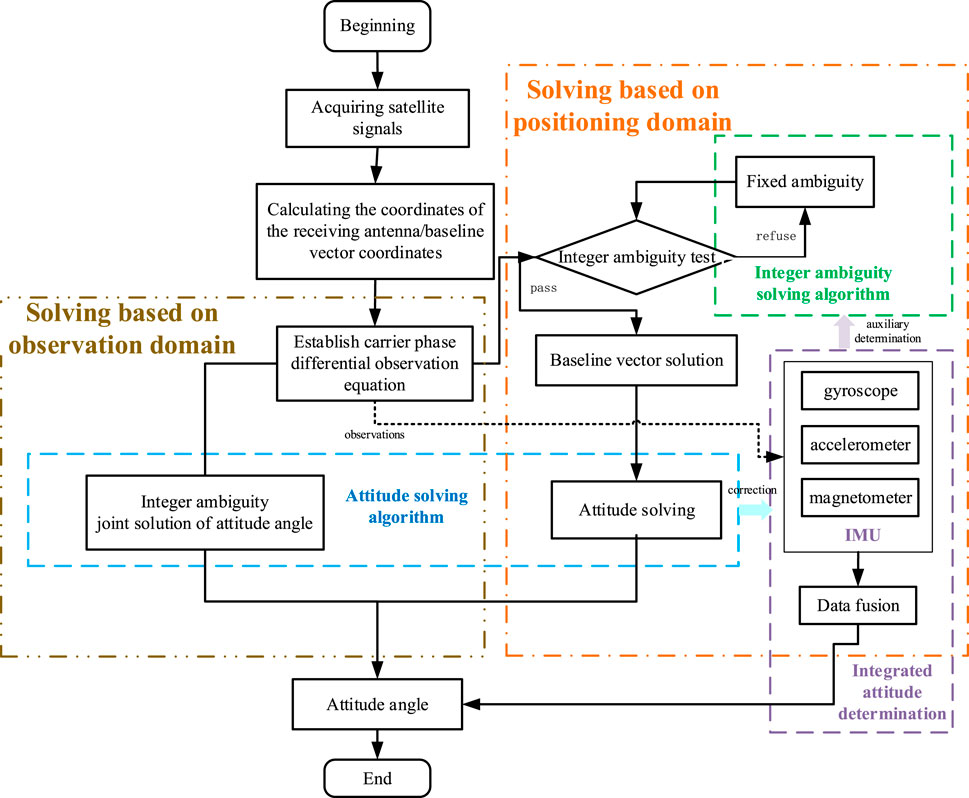
Figure 6. Drone attitude solution flowchart.
The positioning domain solution requires the fixing of integer ambiguities first to obtain accurate baseline vectors, and then to determine the attitude angles, which is straightforward to implement, and obtaining accurate baseline vectors is a prerequisite for obtaining high-accuracy attitude angles. The accuracy of the baseline vectors directly determines the precision of the attitude angle solution [62], while the baseline vector accuracy, in turn, depends heavily on the accuracy with the fixed ambiguity [63]. This method solves sequentially and ignores the correlation between each baseline, reducing the redundancy of the attitude solution, especially when the integer ambiguities are difficult to fix successfully, leading the affection to the determining performance. The observation domain solution solves for the integer ambiguities and the attitude angles simultaneously [64]. It is more complex to implement, although it can solve the integer ambiguities and attitude angles simultaneously, it ignores the correlation between ambiguity resolution and attitude calculation, which can also affect the reliability of the attitude [65].
Whether it is a positioning domain or observation domain solution, the key lies in the solution of integer ambiguities and the attitude calculation algorithm. The determination of integer ambiguities is essential to ensure the accuracy of the baseline vector position solution for UAVs. Given the limited number and length of baselines on RUAVs, the search space for integer ambiguities is large, leading to low search efficiency. The search space is also constrained by the length of the baselines. Therefore, how to achieve fast and effective fixing of ambiguities under the constraints of the UAV’s own conditions is one of the important issues in the attitude determination of RUAVs.
Attitude determination algorithms, after obtaining observational values, use these values to calculate the attitude angle information. The accuracy of the determined attitude angles is often affected by the inherent accuracy of the observational values and observational noise. How to improve the calculation accuracy is also a key issue in attitude determination.
Furthermore, for low-cost RUAVs, dual antennas and low-cost inertial navigation devices are commonly used to achieve the integrity of attitude determination. This not only assists in determining integer ambiguities in GNSS observation solutions but also allows the INS to continue navigation when GNSS fails. The error accumulation phenomenon in the inertial navigation system can also be periodically corrected by GNSS measurement values [66]. In integrated navigation, data fusion processing is crucial. Rotary-wing UAVs are highly dynamic, inertial navigation devices have large measurement noise, and the precision of output measurement values is low. Moreover, the update rate of satellite navigation measurement values is much lower than that of inertial navigation. How to fuse measurement values of different rates is also a key issue that needs to be addressed. A high success rate of ambiguity fixing and efficient attitude calculation are necessary conditions for obtaining real-time high-precision attitude angles [67].
4.1 Integer ambiguity resolution algorithms
The challenge of fixing integer ambiguities lies in the planning of the search space. While reducing the search space and improving search efficiency, it is essential to ensure the correctness of the ambiguity fixing. Faced with the continuous change of the UAV’s spatial position between epochs, a robust On The Fly (OTF) integer ambiguity determination algorithm is required. Based on different ambiguity search spaces, they can be categorized into observation domain-based, coordinate domain-based, and ambiguity domain-based ambiguity resolution [68], with common integer ambiguity resolution methods shown in Table 5.
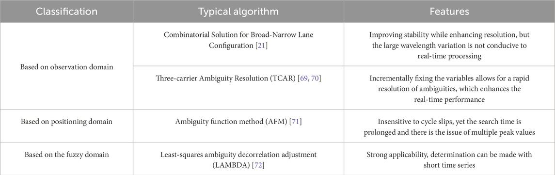
Table 5. Common algorithms for solving integer ambiguity.
Table 5 shows that among the three types of integer ambiguity resolution, the observation domain-based method is the simplest to implement. It relies on the linear combination of carrier frequencies of different wavelengths to obtain a shorter wavelength, thereby reducing the ambiguity fixing error. The TCAR method, based on wide and narrow lanes, uses pseudo-range to assist in ambiguity determination. Since there is no ambiguity search problem, the calculation speed is fast. However, in a dynamic environment, the measurement accuracy decreases due to the influence of receiver performance and observation conditions [69]. Auxiliary information can be used to improve the calculation accuracy in a high-dynamic environment, such as the geometry-free and ionospheric-free TCAR (GIF-TCAR) [70] and the TCAR method assisted by INS (iTCAR) [71].
The positioning domain-based solution method first obtains the initial coordinate position, constructs an ambiguity function around the initial coordinate position, and traverses the global space to get the optimal estimate of the ambiguity function. In response to the long search time and multi-peak problem of AFM, there are also different solutions. For example, Han [73] uses multi-frequency combinations to determine the search step in AFM, reducing the search time; Zhao [74] uses multi-baseline constraints to solve the multi-peak problem of AFM; Wang [75] proposes the AFM under the initial pitch angle constraint (Pitch-constrained Ambiguity Function Method, PCAFM), which can reduce the search range but is very sensitive to the search step size. Since it takes the positioning coordinates as the search basis, the accuracy of the final fixed integer ambiguity is largely limited by the initial positioning accuracy.
The ambiguity domain-based solution is a more commonly used method in practice. The LAMBDA method proposed by Professor Teunissen [76] is the most widely used and effective method in engineering practice. It can solve the integer ambiguity in observation methods such as single-frequency, dual-frequency, non-differential, and single-dual differences. By continuously observing over a short period, the ambiguity can be fixed [77, 78]. The core of the algorithm is based on the Integer Least-Squares principle (ILS) shown in Equation 6 [79]. The integer solution of the ambiguity is the integer least-squares solution of Equation 7. By using the Z-transform in Equation 8, the search space is decorrelated, and finally, a sequential search method is used to obtain the integer solution, and then the inverse transformation is used to obtain the expected solution [72].
Where
The traditional LAMBDA algorithm has high computational complexity and wastes a lot of time during the variance reordering process. The generated search space is inappropriate, leading to low search efficiency, and it cannot utilize the known prior conditions of the baseline to reduce the search space. To address the shortcomings of the traditional LAMBDA algorithm, many scholars have proposed improvements in the decorrelation processing of the covariance matrix, the determination of the integer solution search space, and the search method for the integer solution in the general LAMBDA algorithm. This has led to the evolution of various improved LAMBDA algorithms, continuously enhancing the search efficiency and fixing success rate of the integer ambiguities, as shown in Table 6.
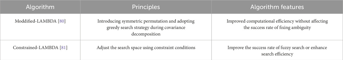
Table 6. Least-squares ambiguity decorrelation adjustment.
In Table 6, introducing constraint conditions is the main direction for the improvement of the LAMBDA method. Especially when the floating-point solution and the covariance matrix are not accurate enough, constraint conditions can improve the search efficiency and the success rate of fixing [81]. Common constraint methods include baseline constraints [82], triangular constraints [83], affine constraints [84], and so on. Teunissen used the LAMBDA method with constraint conditions to calculate the integer ambiguities and verified the advantages of the algorithm in terms of calculation stability and success rate through on-board dynamic experiments [85]. Shao [86] combines the M-LAMBDA algorithm with the C-LAMBDA algorithm, improving the success rate while reducing computational complexity and ensuring computational efficiency.
In response to the challenge of ambiguity fixing in low satellite visibility environments, there has been considerable research. Chen [87] adopts a spherical constraint on the ambiguity space to improve the success rate of integer ambiguity fixing, while also employing a joint search strategy in both the coordinate domain and ambiguity domain to achieve attitude determination under low satellite visibility. Giorgi [88] proposes an attitude solution method based on multivariate constraints in the observation domain (multivariate-constrained LAMBDA, MC-LAMBDA), which is not limited by the number of antennas, GNSS system combination methods, or kinematic prior information, and can solve for integer ambiguities and attitude angles simultaneously, significantly improving the success rate of ambiguity fixing. However, due to the consideration of multiple constraint conditions, the computational complexity increases. Liu [89] and Douik [90] improve MC-LAMBDA by using Riemannian optimization to solve nonlinear least squares constraints, reducing computational complexity while ensuring the reliability of ambiguities and the accuracy of attitude.
4.2 Attitude determination algorithms
The attitude determination algorithms are another significant factor affecting the accuracy of attitude angles. The challenge in calculation lies in achieving a solution with low time complexity while ensuring the accuracy of the solution. Additionally, for scenarios with multiple baselines, how to utilize redundant information to enhance the calculation accuracy is also a hot topic commonly researched by scholars.
Table 7 presents several common attitude determination algorithms. The TRIAD algorithm directly solves for the attitude angles based on the observation matrix without the need for iterative optimization, making it simple to implement with low computational complexity. However, it is limited by the baseline layout, cannot utilize redundant information, and thus has lower solution accuracy.
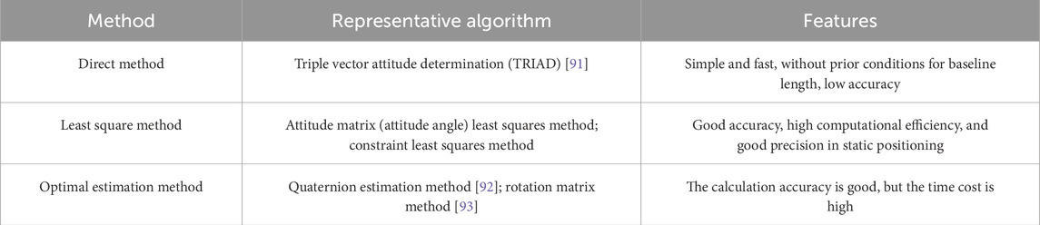
Table 7. Common pose solving methods.
The least squares method solves for the attitude angles or attitude matrix using the classical principle of least squares. It is computationally efficient and can accurately approximate actual data. The least squares method can significantly improve the accuracy of the heading angle, but its improvement on the pitch and roll angles is not significant [94]. Liu [95] uses antenna arrays and the integer property of ambiguities to constrain the least squares solution, allowing for direct calculation of attitude angles, especially in challenging environments with single-system, single-frequency, and single-epoch conditions, further enhancing computational efficiency. Due to the constant state vector, the least squares method is suitable for static or low-dynamic attitude determination but performs poorly in high-dynamic conditions typical of UAVs.
The optimal estimation method transforms the attitude angle solution into a Wahba problem [96], taking into account the noise and uncertainty of the observational data, and adopts an iterative strategy to find the optimal solution or a non-iterative method to find a suboptimal solution. It establishes a cost function based on a large amount of observational data to achieve the estimation of attitude elements. Among them, the quaternion estimation (QUEST) algorithm, proposed by Shuster, uses quaternions to transform the process of solving the rotation matrix into the process of minimizing the cost function. This algorithm does not require initial values and is flexible in processing, but can only estimate the optimal value based on the current state. To address the limitations of the QUEST method, Bar-Itzha [97] proposed the REQUST algorithm, which uses historical state information for recursive solution, further improving the accuracy and robustness of the estimated values.
4.3 GNSS/INS integrated attitude determination
Utilizing GNSS for attitude determination can yield high-precision, cost-effective measurement outcomes. However, in complex environments where signals may be obstructed or interfered with, relying solely on the GNSS system for attitude determination becomes challenging. RUAVs, which are limited by the number of equipped antennas, use a two-antenna single-baseline setup allows for the measurement of only two attitude angles: the heading and pitch angles. Therefore, to ensure the integrity of the attitude determination system under various conditions and to obtain complete attitude information, multi-sensor fusion for attitude determination is an effective approach to achieving cost-effective and high-precision measurement [98].
As depicted in Figure 7, the combination of satellite navigation and inertial navigation for attitude determination leverages the inertial navigation system to assist the GNSS system, providing backup navigation for a short period during GNSS signal interruptions [99]. The Inertial Measurement Unit (IMU), which includes accelerometers and gyroscopes, provides raw measurement data [100]. The measurement values or states output by the GNSS component and the INS component are fused to varying degrees through a composite filter to jointly obtain the vehicle’s attitude information. The IMU can detect the drone’s attitude and balance status in real-time during flight and feedback to the control center, making up for the low rate of GNSS output measurement [101].
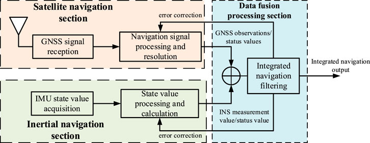
Figure 7. GPS/INS integrated navigation structure.
Integrated navigation is generally divided into three categories based on the degree of data fusion: loose integration, tight integration, and ultra-tight integration [102]. Loose integration fuses the output results of the GNSS system (position, velocity, attitude angles) with the output of the INS system, where the two systems work independently, making it simple to implement with good redundancy [103]. Tight integration fuses the GNSS observations such as pseudo-range and carrier phase with the state values of the INS system’s gyroscopes and accelerometers, achieving better measurement accuracy under low signal-to-noise ratios [104]. Ultra-tight integration deeply integrates the GNSS receiver with the components of the INS system, starting the fusion from the satellite tracking loop [105], using the INS system information to adjust the GNSS tracking loop bandwidth, and improving the signal-to-noise ratio, which has superior calculation accuracy and robustness under interference conditions. The high cost of implementing ultra-tight integration does not meet the low-cost requirements of UAVs, so UAVs often adopt loose or tight integration of gyroscopes, accelerometers with the GNSS system.
The key to combination navigation is the data fusion model and the filtering update algorithm, which combines and smooths the output values of the two systems to reduce measurement errors. Common filtering fusion algorithms are shown in Table 8.
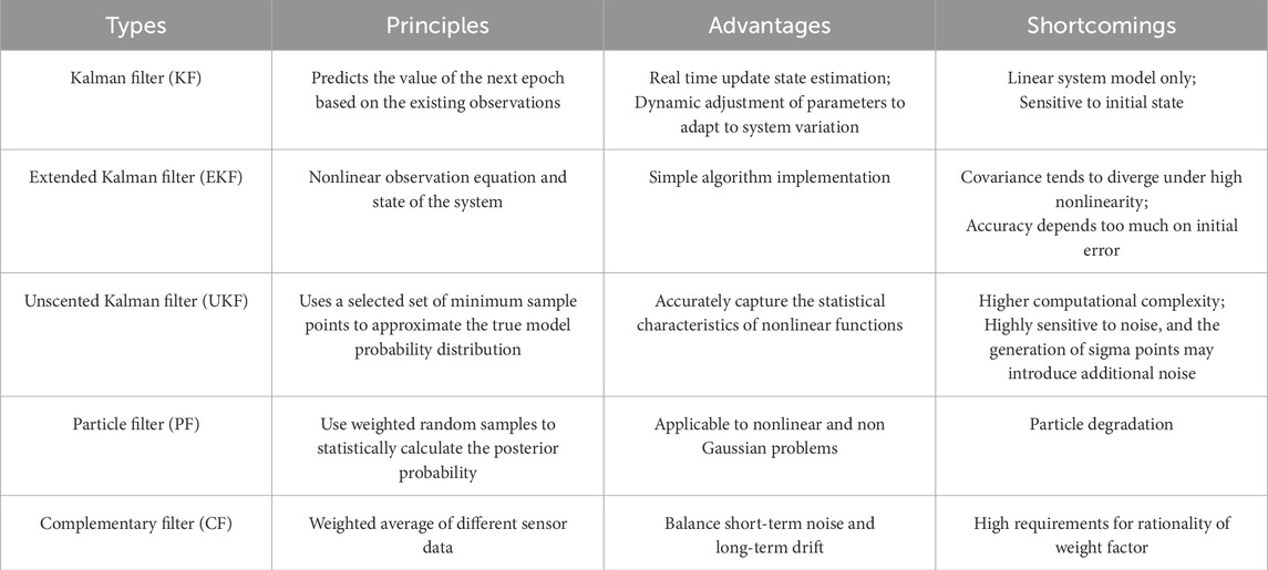
Table 8. Typical filtering algorithm.
As shown in Table 8, the KF is an optimal regression data processing method that reasonably and has been applied in various fields such as multi-system data processing and fusion, space orbit prediction, and wireless positioning [106, 107]. However, the Kalman filter is only suitable for linear systems. To apply it to the baseline solution of GNSS nonlinear observation equations, the Kalman filter needs to be improved, resulting in the Extended Kalman Filter (EKF) [108], Unscented Kalman Filtering (UKF) [109], Particle Filter (PF) [110], Complementary Kalman Filter (CKF) [111], and so on. The Extended Kalman Filter (EKF) is the simplest to implement, but its accuracy depends on the initial error and the degree of approximation to the true model [112]. The Unscented Kalman Filter (UKF) uses a set of sigma points to approximate the true model, while the Particle Filter (PF) weights these sampling points to further enhance accuracy and eliminate the impact of multipath errors in the signal [110]. However, the Particle Filter suffers from the problem of particle degradation, and it is common to combine the Particle Filter with other types of nonlinear Kalman filters to improve particle distribution [112–114]. Complementary filtering can leverage the short-term accuracy of the gyroscope and the long-term stability of the accelerometer to achieve accurate attitude estimation.
The filtering algorithm in integrated navigation can effectively reduce the data error of attitude measurement between different sensors, reduce the impact of measurement noise on the final measured value, and use different sensor data to complement each other to improve the accuracy and reliability of attitude angle. Jwo [25] uses EKF for filtering the attitude estimation represented by quaternions, which can eliminate the noise of the quaternion itself and improve the attitude accuracy. The baseline can also be used to assist the Kalman filter using high-precision baseline prior length information to constrain the Kalman filter iteration process, thereby improving accuracy and robustness [115],. Dong [116] uses sequential adaptive Unscented Kalman filtering, estimating the measurement noise covariance matrix of the heading angle change in real-time, mitigating the problem of drastic noise changes in integrated attitude determination caused by object movement, and providing a stable and accurate heading angle.
In the loose or tight integration navigation of RUAV, different filtering algorithms are used to achieve different degrees of data fusion to obtain reliable and accurate attitude angle For loose integration, Ding [117] constructs an Error State Kalman (ESKF) filter, fusing inertial navigation sensors and GNSS data, continuously integrating the gyroscopic measured angular rate to propagate attitude, and compensating for cumulative errors through measurement updates, achieving combined attitude determination of MEMS systems and low-cost GNSS receivers. For tight integration, Wang [101] combines dual-antenna GNSS and MEMS, verifying that the inertial navigation device can stably measure the heading angle under brief GNSS signal loss. Yan [118] uses dual-rate filtering based on EKF, fusing high-rate high-noise observations and low-rate low-noise observations into an optimal estimation system, achieving real-time attitude determination in complex noise environments.
In addition to filtering out noise through combination, combined navigation attitude determination also helps to fix the integer ambiguity. Xiao [119] proposes a three-frequency differential GNSS/INS tight integration, using three-frequency solutions to improve the speed of measurement values and integer ambiguity fixing, and using tight integration to weaken the impact of TCAR algorithm instability on the results. Gao [120] proposes a new tight integration GNSS/MEMS model, using a single filter to achieve optimal estimation of attitude drift, gyro zero bias, and ambiguity, effectively improving the ambiguity fixing rate and reducing attitude error compared to a single GNSS system.
The integration of satellite navigation and inertial navigation can combine the advantages of the two systems to achieve complementary performance. The high-precision measurement values provided by the satellite navigation system help to reduce the cumulative error of the inertial navigation system, while the inertial navigation system does not require external signal input and can act as a backup navigation in the event of GNSS signal occlusion or interference, taking over the navigation task for a short period [121, 122].
5 Challenges
5.1 Real-time attitude determination under high dynamics
Currently, the use of GNSS for attitude determination is often aimed at the attitude determination of vehicle platforms, where the main change in the vehicle’s attitude angles is in the heading angle, and the change is relatively slow. In contrast, rotary-wing UAVs have high dynamics, and during complex motion processes, multiple attitude angles change within a short period of time. Existing research is better for the attitude determination of vehicles or low-dynamic aircraft, but there is less research on the high dynamics of rotary-wing UAVs. However, the attitude determination of UAVs under high dynamics is crucial, as only by accurately grasping the real-time motion state of the UAV can the safe execution of tasks be ensured.
The high-dynamic flight of UAVs will lead to rapid changes in the baseline vectors formed by the receiving machinery, posing certain difficulties for baseline calculation. Since the premise of accurate baseline calculation is the determination of integer ambiguities, most existing ambiguity determination methods rely on searching in the ambiguity domain. Under high dynamics, the ambiguity space range is large, so how to constrain the ambiguity space, reduce the size of the search space, and thereby improve the fixing rate is a challenge [123]. The relatively effective MC-LAMBDA method, described in Section 4.1, can effectively reduce the search space by relying on multiple variables for constraints, but due to the consideration of multiple constraint conditions at the same time, it leads to increased algorithm complexity and to some extent, reduced search efficiency. Therefore, how to consider the accuracy of baseline calculation under high dynamics, especially the rapid determination of integer ambiguities under high dynamics, is a current major challenge.
High-precision attitude determination under high dynamics requires not only the method of solution but also the reliability of the solution results. Since the fixing of integer ambiguities is a key link affecting attitude determination, existing inspection methods mainly inspect the accuracy and stability of ambiguity fixing, thereby reflecting the reliability of attitude determination. Commonly used methods are based on positioning domain judgment, and under the premise of baseline constraints, the selected judgment threshold is largely related to the length of the baseline [124, 125]. For the attitude determination of RUAVs with short baselines, the requirements for the judgment threshold may be more stringent. Therefore, whether a method for attitude determination integrity inspection suitable for UAVs with short baseline systems can be developed, which can make judgments on attitude determination integrity without the need for prior conditions of baseline length, or relying on a small amount of baseline redundancy information, is a challenge.
5.2 Effective response to navigation interferences
Using GNSS signals for UAV attitude determination often faces the issue of navigation interference, where jamming and spoofing are the most common types of satellite navigation interference. The integrity of navigation services determines whether the UAV can work properly [126]. Especially for UAVs that require high-precision positioning and attitude determination equipment, once they encounter navigation interference, as depicted in Section 3.3, they will obtain incorrect position and attitude information, lose control of the UAV’s motion state, and thus affect its operational effectiveness.
Jamming interference is low-cost, reliable, easy to implement, has a wide coverage range, and is widely used in various scenarios. A 1W jamming interference source can interfere with the maximum distance of about 16.96 km under ideal conditions [42]. Although the probability of successful implementation of jamming interference has been reduced with the application of frequency domain filtering technology, anti-jamming antenna technology, pseudo-satellite technology, and integrated navigation, etc., for small aircraft such as rotary-wing UAVs, it is still difficult to effectively resist jamming interference without external assistance. Although small inertial navigation devices can be equipped to take over the satellite navigation equipment and continue navigation in the face of interference, due to the serious accumulation of errors and low accuracy of small inertial navigation devices, the overall system navigation error increases without the error correction of the satellite navigation system, which still reduces the operational effectiveness of the UAV.
Compared to jamming interference, spoofing interference is characterized by its strong concealment, high threat, and low cost, and can deceive the UAV into flying along a specified trajectory [127]. With a low-cost spoofing device, a certain spoofing effect can be achieved [128, 129]. Generally, when the deceptive signal power is 3dB higher than the real signal power, the jammer can be deceived. The interferer fuses and calculates high-precision spoofing signals based on the UAV’s position, speed, and other status information, making the spoofing signals highly similar to the real signals, thereby completing covert deception [130]. Especially for UAVs using public service navigation signals, due to the openness of the signal system and the use of less encryption and authentication, they are more susceptible to spoofing [131]. From random position spoofing [132], fixed-point position spoofing [133], delayed message spoofing [134], to state estimation value spoofing [135], different types of spoofing interference can severely affect the normal flight of UAVs. The implementation approaches also vary, such as adding interference to the receiver’s phase-locked loop [136], and gradually guiding with trajectories of different Doppler shifts and delays [137], etc.
Addressing the diverse and complex satellite navigation interference methods of today, designing anti-satellite navigation interference systems suitable for rotary-wing UAVs is an urgent problem that needs to be solved. When facing jamming interference, the challenge is to ensure the normal operation of the UAV navigation receiver and to mitigate the effects of jamming signals. When facing spoofing interference, the system should be able to autonomously and effectively detect spoofing according to the abnormal receiving phenomena without adding extra weight or hardware requirements to the UAV. Compared with the mature deception detection without too many hardware requirements, the existing UAV is more difficult to suppress the suppression interference. Improving the survival rate of UAV under suppression jamming is the key problem to be solved. Existing anti-jamming methods often employ array antennas, but these can introduce significant phase pattern changes that affect the quality of observations [138]. Moreover, array antennas can only counteract interference from a limited number of directions, and their anti-jamming performance is limited in complex environments with multi-directional interference. At the same time, the use of array antenna will increase the hardware overhead and load. Therefore, achieving low-cost navigation anti-jamming in complex environments while ensuring the UAV’s positioning and attitude determination is a significant challenge for rotary-wing UAVs.
5.3 Intelligent response to Multi-GNSS system integration
The current GNSS systems have been developed and refined, with each navigation system capable of independently performing positioning, navigation, and timing tasks. Utilizing multi-system GNSS can significantly increase the number of observable satellites, improve the geometric configuration of the satellite constellation, as depicted in Section 3.3, reduce reception costs, and obtain higher quality observational data, thereby enhancing measurement accuracy. Especially in challenging environments where satellite access is limited, when one system fails or is unavailable, another system can provide operational redundancy [139].
Due to the low cost of current navigation equipment, multiple satellite navigation systems can be implemented on small-sized devices. As shown in Figure 8, the HX-CH3602A and HX-CH6601A from Beidou Xingtong are two receiver antennas specifically designed for small UAVs. They can respectively achieve triple-system tri-frequency reception for GPS L1, BDS B1, and GLONASS L1, and triple-system six-frequency reception for GPS L1/L2, GLONASS L1/L2, and BDS B1/B2.
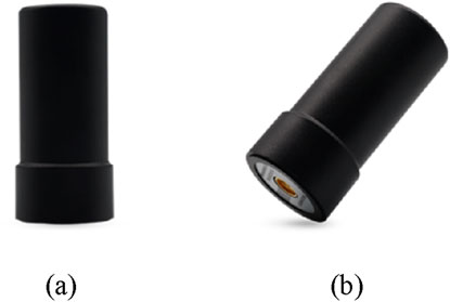
Figure 8. Beidou Satellite Communication System’s receiving antennas specially used for small unmanned aerial vehicle. (A) HX-CH3602A. (B) HX-CH5601A.
The current attitude determination using multi-system GNSS is mainly focused on the combination of different systems on a single frequency. Teunissen [139] conducted simulation studies on the attitude determination of Galileo and GPS single-frequency combined data, obtaining relatively stable expected results, which verified the ability to use backup satellite data for instantaneous attitude determination in a disturbed environment. Zamanpardaz [140, 141] compared and analyzed the Indian Regional Navigation Satellite System (IRNSS) and GPS Block IIF on the L5 frequency point. When the two systems were combined for attitude determination, the ambiguity dilution of precision (ADOP) was significantly improved, and both the integer ambiguity fixing success rate and attitude accuracy were significantly enhanced [142]. Zhao [143] confirmed the improvement in attitude determination performance when GPS/BDS/GALILEO were used in a tight combination, with the percentages of pitch error, yaw error, and roll error within 2° in a complex environment increasing by 6.1%, 8.07%, and 13.43%, respectively, and the ambiguity fixing rate increased by 14.78%. Shu [144] conducted attitude determination with the combination of GPS, BDS, Galileo, and GLONASS, confirming that the combined attitude determination can significantly improve attitude accuracy on a moving vehicle platform. Yang [145] propose GPS/BDS dual-antenna attitude determination model which obviously improve the fixing rates, such as 16.0% improved in the static experiment and 23.6% in dynamic experiment. Although the aforementioned research can enhance the attitude measurement performance by utilizing GNSS signals at the same frequency point, they did not focus on attitude determination using different frequency point signal combinations under multi-GNSS systems.
In addition, common jamming and spoofing interferences are usually targeted at a specific system within the GNSS, making it difficult to interfere with the entire GNSS system simultaneously. By leveraging the mutual backup among navigation systems, it is possible to continue navigation using another system when faced with interference targeting a particular satellite navigation system. Therefore, under the current conditions where GNSS systems are increasingly refined, how to better utilize multiple GNSS systems to complete integrated attitude determination, mutual integration, and backup to enhance attitude determination accuracy in complex environments and resist navigation interference is a challenge.
Several factors need to be considered, such as the performance comparison of different navigation systems in UAV positioning and attitude determination applications; the basis for selecting signal combinations from different navigation system frequency points; the selection of integer ambiguity fixing methods and attitude determination algorithms under multi-system GNSS integrated attitude determination; the ability of different navigation systems to counteract jamming and spoofing interference; ensuring the continuity and accuracy of positioning and attitude determination results during system switching, etc. Moreover, when performing integrated attitude determination with multiple GNSS systems, the issue of inter-system bias (ISB) between systems also needs to be addressed [139, 146].
6 Conclusion
The article primarily discusses the current state and challenges of attitude determination for rotary-wing UAVs based on the GNSS. Attitude information is a necessary condition for the safe flight of UAVs. The article focuses on three main aspects of UAV attitude determination: integer ambiguity resolution, attitude calculation, and integrated navigation. The determination of integer ambiguities is a key factor affecting the accuracy of UAV carrier phase differential measurements. Only by obtaining accurate and reliable ambiguities can the precise baseline be calculated, which in turn determines the attitude angles. While integer ambiguity resolution has been proven to be reliable and accurate when searching within the ambiguity domain constrained by baselines, further constraints are needed for the high-dynamic mobile carrier. The attitude calculation method requires further improvement in computational complexity to meet the real-time attitude acquisition requirements of UAVs. Integrated navigation is the current development trend for achieving low-cost attitude measurement, and the integration of data from integrated navigation is an important direction for research. Filtering different navigation systems’ data to reduce the impact of observation noise on attitude calculation and enhance the performance of integrated navigation is essential.
At the same time, due to the vulnerability of satellite navigation, using GNSS for attitude measurement is susceptible to common navigation interferences. Once interference occurs, UAVs may lose directional control, posing a significant safety risk. Therefore, further research is needed to enhance the anti-interference capabilities of rotary-wing UAV navigation. Given that current GNSS systems have matured and various satellite navigation systems can be used for attitude measurement, integrating multiple systems could be a potential approach to improving anti-interference capabilities. This not only enhances the accuracy of UAV attitude measurement but also improves the UAV’s ability to continue navigation when encountering interference.
Author contributions
YZ: Investigation, Writing–original draft. ZL: Methodology, Writing–original draft. YX: Formal Analysis, Writing–original draft. BR: Methodology, Writing–original draft. YY: Supervision, Writing–original draft. SN: Validation, Visualization, Writing–original draft.
Funding
The author(s) declare that financial support was received for the research, authorship, and/or publication of this article. (1) National Nature Science Foundation of China under Grant (U20A0193). (2) The science and technology innovation Program of Hunan Province (2021RC3073).
Conflict of interest
Author YY was employed by Hunan Xinghe Electronics Co. LTD.
The remaining authors declare that the research was conducted in the absence of any commercial or financial relationships that could be construed as a potential conflict of interest.
Publisher’s note
All claims expressed in this article are solely those of the authors and do not necessarily represent those of their affiliated organizations, or those of the publisher, the editors and the reviewers. Any product that may be evaluated in this article, or claim that may be made by its manufacturer, is not guaranteed or endorsed by the publisher.
References
1. Sonugür G. A Review of quadrotor UAV: control and SLAM methodologies ranging from conventional to innovative approaches. Robot Auton Syst (2023) 161:104342. doi:10.1016/j.robot.2022.104342
2. Gupta L, Jain R, Vaszkun G. Survey of important issues in UAV communication networks. IEEE Commun Surv Tutorials (2016) 18(2):1123–52. doi:10.1109/comst.2015.2495297
3. Mozaffari M, Saad W, Bennis M, Nam YH, Debbah M. A tutorial on UAVs for wireless networks: applications, challenges, and open problems. IEEE Commun Surv Tutorials (2019) 21(3):2334–60. doi:10.1109/comst.2019.2902862
4. Xiaoqian T, Feicheng Z, Zhengbing T, Hongying W. Nonlinear extended kalman filter for attitude estimation of the fixed-wing UAV. Int J Opt (2022) 2022:1–9. doi:10.1155/2022/7883851
5. Fan HB, Guo JL, Luo GW. Application of drones in modern warfare. Light Weapons (2022) 9:32–4. doi:10.3969/j.issn.1000-8810.2022.09.007
6. Jin Y, Gu QX. Overview of foreign military UAV equipment technology development in 2023. Tactical Missile Tech (2024) 1:33–47. doi:10.16358/j.issn.1009-1300.20240501
7. Yu W, Hou XL. Analyzing the application of drone operations from the Nagorno-Karabakh conflict. Ship Mar Elect Eng (2022) 42(10):8–12. doi:10.3969/j.issn.1672-9730.2022.10.003
8. Su RC, Xiang WH, Miao GC, Wang D. Operational application and analysis of drones in the Nagorno-Karabakh Conflict. Missile J (2021) 1:65–70. doi:10.16338/j.issn.1009-1319.20200330
9. Liao KN. Research on attitude calculation and control method of quadrotor unmanned aerial vehicle. Mianyang: Southwest University of Science and Technology (2023). dissertation/master's thesis.
10. Leishman JG. Etienne oehmichen: scientist, engineer and helicopter pioneer. In: AHS international 62nd annual forum proceedings vol3:vertical flight:leading through innovation (2006).
11. Fan BK, Li Y, Zhang RY, Fu QQ. Review on the technological development and application of UAV systems. Chin J Elect (2020) 29(2):199–207. doi:10.1049/cje.2019.12.006
12. Hoffmann GM, Huang HM, Waslander SL, Tomlin CJ. Quadrotor helicopter flight dynamics and control: theory and experiment. In: AIAA guidance, navigation, and control conference proceedings (2007).
13. Hoffmann GM, Waslander SL, Vitus MP, Huang H, Gillula J, Pradeep V, et al. Stanford testbed of autonomous rotorcraft for multi-agent control. In: 2009 IEEE/RSJ international conference on intelligent robots and systems (2009). p. 404–5.
14. DJI. Technical support for mavic air 2 (2024). Available from: https://www.dji.com/cn/support/product/mavic-air-2 (Accessed April 20, 2024).
15. Ebeid E, Skriver M, Jin J. A survey on open-source flight control platforms of unmanned aerial vehicle. In: 2017 euromicro conference on digital system design (DSD) (2017). p. 396–402.
16. Cetinsaya B, Reiners D, Cruz-Neira C. From PID to swarms: a decade of advancements in drone control and path planning - a systematic review (2013–2023). Swarm Evol Comput (2024) 89:101626. doi:10.1016/j.swevo.2024.101626
17. Rezaee MR, Hamid NAWA, Hussin M, Zukarnain ZA. Comprehensive review of drones collision avoidance schemes: challenges and open issues. IEEE Trans Intell Transportation Syst (2024) 25(7):6397–426. doi:10.1109/tits.2024.3375893
18. Zhang QL, Wang YM, Cheng EW, Chen YZ. Assessment method for electromagnetic interference situation of UAV satellite navigation system. J Natl Univ Defense Tech (2022). doi:10.11887/j.cn.202206014
19. Kim S-G, Lee E, Hong I-P, Yook J-G. Review of intentional electromagnetic interference on UAV sensor modules and experimental study. Sensors (Basel, Switzerland) (2022) 22(6):2384. doi:10.3390/s22062384
20. Xiao K. Research on theory and method of multi-frequency GNSS/INS integrated precise positioning and attitude determination. Zhengzhou, China: Information Engineering University of Strategic Support Force (2020). dissertation/master's thesis.
21. Xie G. GPS principles and receiver design. Beijing: Publishing House of Electronics Industry (2017).
22. Chen XG, Wang ES, Ren X, Shu WS, Wu LY, Xu S. Design of UAV system based on Beidou navigation. Electron Devices (2021) 44(5):1248–53. doi:10.3969/j.issn.1005-9490.2021.05.037
23. Giorgi G, Teunissen JGP. GNSS carrier phase-based attitude determination. London: Intech Open (2012).
24. Gong A, Zhao XB, Pang C, Duan R, Wang Y. GNSS single frequency, single epoch reliable attitude determination method with baseline vector constraint. Sensors (2015) 15(12):30093–103. doi:10.3390/s151229774
25. Jwo DJ. Estimation of quaternion motion for GPS-based attitude determination using the extended Kalman filter. Comput Mater Continua (2020) 66(2):2105–26. doi:10.32604/cmc.2020.014241
26. Shu TG, Kay SL. Survey of global-positioning-system-based attitude determination algorithms. J Guidance, Control Dyn (2017) 40(6):1321–35. doi:10.2514/1.G002504
27. Sabatini R, Salazar LR, Rodriguez L, Kaharkar A, Bartel C, Shaid T Carrier-phase GNSS attitude determination and control system for unmanned aerial vehicle applications. ARPN J Syst Softw (2012) 297–322. doi:10.4172/2168-9792.1000115
28. Xu JN, Zhu T, Bian HW. Overview of GPS attitude measurement technology. J Naval Univ Eng (2003) 3:17–22. doi:10.3969/j.issn.1009-3486.2003.03.005
29. Hermann RB. A simulation of the navigation and orientation potential of the Ti-Agr. Mar Geodesy (1985) 9(2):133–43. doi:10.1080/15210608509379522
30. Kruczynski LR, Li PC, Evans AG, Hermann BR Using GPS to determine vehicle attitude: USS Yorktown test results (1989).
31. Zheng GZ. Discussion on Ashtech GPS 3DF attitude measurement system. Geology Mining Surv Mapp (1994) 1994(2). doi:10.16864/j.cnki.dkch.1994.02.001
32. Wilson GJ, Tonnemacher JD. A GPS attitude determination system. The J Navigation (1992) 45(2):192–204. doi:10.1017/s0373463300010699
33. Guo WL, Pan YC, Zhai ZR. A method for heading and attitude measurement based on dual-antenna GPS receiver. Radio Eng (2012) 42(5):49–52. doi:10.3969/j.issn.1003-3106.2012.05.016
34. Tang JM, Wang Q, Ye S. Data acquisition and processing method of GPS-Beeline attitude measurement system. Navigation (2004)(1) 46–50.
35. GNSS-INS. Three-antenna full-attitude measurement and positioning integrated system ZH6000A. Shanghai, China: Shanghai Zihang Electronic Technology Co., Ltd (2024). Available from: https://www.zeenav.com/product-detail/gins-th.html (Accessed December 26, 2024).
36. GNSS-INS. Fiber optic GNSS/INS combined inertial navigation system SIN-INS3000 - integrated navigation products. Xi'an, China: Xi'an Sine Wave Measurement and Control Technology Co., Ltd (2024). Available from: http://www.fog-ins.com/content/?150.html (Accessed December 26, 2024).
37. Ericcotech. High-precision GNSS+INS integrated navigation: mastering speed, Position, Attitude Inertial Tech Supplier. (2024). Available from: https://www.ericcotech.com/?article/187.html (Accessed December 26, 2024).
38. MTI710 GNSS/INS. Xi'an precision measurement and control Co., ltd (2024). Available from: https://www.siliconmems.com/dproduct_detail/id-165.html (Accessed December 26, 2024).
39. MicroStrain 3DM-GX5-GNSS/INS. MicroStrain by HBK (2024). Available from: https://www.microstrain.com/inertial-sensors/3DM-GX5-4.5 (Accessed December 26, 2024).
40. Ding W, Sun W, Yan H, Li W, Jiang Y, Gao Y. Low-cost dual-antenna GNSS-based heading and pitch angles estimation considering baseline length constraint. Measurement (2025) 239:115492. doi:10.1016/j.measurement.2024.115492
41. Wu Y, Sun C. Dual-antenna GPS-based UAV attitude determination method and accuracy analysis. J Phys Conf Ser (2023) 2489:012035. doi:10.1088/1742-6596/2489/1/012035
42. Jiao B, Cong DW. Prospects of navigation jamming technology application in UAV defense. Radio Eng (2021) 51(10):1019–24. doi:10.3969/j.issn.1003-3106.2021.10.001
43. Xinhua News Agency. Drone show in xi’an goes wrong with “garbled code”. Possibly Due to Signal Interference (2024). Available from: https://baijiahao.baidu.com/s?id=1599489299738948292&wfr=spider&for=pc (Accessed April 20, 2024).
44. Wu YW. Battlefield applications of unmanned aerial vehicles in complex electromagnetic environments. Cruise Missiles (2011) 1:30–5. doi:10.3969/j.issn.1006-141X.2013.02.001
45. Wang XZ, Yao YB, Xu CQ, Zhao Y, Zhang H. An improved single-epoch attitude determination method for low-cost single-frequency GNSS receivers. Remote Sensing (2021) 13(14):2746. doi:10.3390/rs13142746
46. Liang X, Huang ZG, Qin HL. A new rapid integer ambiguity resolution of GNSS phase-only dynamic differential positioning. IEEE Geosci Remote Sensing Lett (2022) 19:1–5. doi:10.1109/lgrs.2021.3117093
47. Wu HT, Zhao XB, Pang CL, Zhang L, Feng B. Multivariate constrained GNSS real-time full attitude determination based on attitude domain search. J Navigation (2019) 72(2):483–502. doi:10.1017/s0373463318000784
48. Zamanpardaz S, Teunissen PJG, Nadarajah N. IRNSS/NavIC L5 attitude determination. SENSORS (2017) 17(2):274. doi:10.3390/s17020274
49. Shuster MD. A survey of attitude representations. J Astronautical Sci (1993) 41(4):439–517. doi:10.1109/7.259548
50. Diebel J. Representing attitude: euler angles, unit quaternions, and rotation vectors. Matrix (2006) 58(15-16):1–35.
51. Axelrad P, Behre CP. Satellite attitude determination based on GPS signal-to-noise ratio. Proc IEEE (1999) 87(1):133–44. doi:10.1109/5.736346
52. Wang C, Walker RA, Moody MP. Single antenna attitude algorithm for nonuniform antenna gain patterns. J Spacecraft Rockets (2007) 44(1):221–9. doi:10.2514/1.19428
53. Medina D, Vilà-Valls J, Hesselbarth A, Ziebold R, García J. On the recursive joint position and attitude determination in multi-antenna GNSS platforms. Remote Sensing (2020) 12(12):1955. doi:10.3390/rs12121955
54. Henkel P, Lamm M, Mittmann U, Fritzel T, Strauß R, Steinert H-J, et al. Verification of RTK positioning of UAVs with high-precision laser tracker. In: 2022 16th European conference on antennas and propagation (EuCAP) (2022). p. 1–5.
55. Ding W, Sun W, Gao Y, Wu J Carrier phase-based precise heading and pitch estimation using a low-cost GNSS Receiver. Remote Sensing (2021) 13(18):3642. doi:10.3390/rs13183642
58. Wu M, Luo S, Li JH, Liu W. Characterization of GNSS line bias and BDS-3 attitude determination with single-differenced observations from common-clock receiver. IEEE Sensors J (2023) 23(18):21842–52. doi:10.1109/jsen.2023.3300148
59. Nie B, Cai Z, Zhao J, Wang Y. Motion transformation solutions based on Euler angle perturbation model. Measurement (2025) 240:115631. doi:10.1016/j.measurement.2024.115631
60. An X, Meng X, Jiang W. Multi-constellation GNSS precise point positioning with multi-frequency raw observations and dual-frequency observations of ionospheric-free linear combination. Satellite Navigation (2020) 1(1):7. doi:10.1186/s43020-020-0009-x
61. Liu Y, Wang S, Hu L, Han C, Chai D. Analysis of the effect of GNSS interference on high-precision positioning applications of satellite navigation systems. In: 2021 IEEE international geoscience and remote sensing symposium IGARSS (2021). p. 8554–7.
62. OliaZadeh N, Landry R, Yeste-Ojeda OA, Gagnon E, Wong F. GPS-based attitude determination using RLS and LAMBDA methods. In: 2015 international conference on localization and GNSS (ICL-GNSS) (2015). p. 1–7.
63. Odolinski R, Teunissen PJG. Best integer equivariant estimation: performance analysis using real data collected by low-cost, single- and dual-frequency, multi-GNSS receivers for short-to long-baseline RTK positioning. J Geodesy (2020) 94(9):91–17. doi:10.1007/s00190-020-01423-2
64. Chen BW, Chang GB, Li SQ, Deng K. Analytical and iterative solutions to GNSS attitude determination problem in measurement domain. Math Probl Eng (2019). doi:10.1155/2019/7908675
65. Zhao L, Li N, Li L, Zhang Y, Cheng C. Real-time GNSS-based attitude determination in the measurement domain. Sensors (2017) 17(2):296. doi:10.3390/s17020296
66. Zhu F, Hu Z, Liu W, Zhang X. Dual-antenna GNSS integrated with MEMS for reliable and continuous attitude determination in challenged environments. IEEE Sensors J (2019) 19(9):3449–61. doi:10.1109/jsen.2019.2891783
67. Giorgi G, Teunissen PJG. Carrier phase GNSS attitude determination with the multivariate constrained LAMBDA method. In: 2010 IEEE aerospace conference (2010). p. 1–12.
68. Zhang JY. Research on theory and method of GNSS integer ambiguity estimation and testing. Changsha, China: National University of Defense Technology (2019).
69. Forssell B, Martin-Neira M, Harrisz RA. Carrier phase ambiguity resolution in GNSS-2. In: Proceedings of the 10th international technical meeting of the satellite division of the Institute of navigation (ION GPS 1997) (1997). p. 1727–36.
70. Vollath U, Birnbach S, Landau L, Fraile-Ordoñez JM, Martí-Neira M. Analysis of three-carrier ambiguity resolution technique for precise relative positioning in GNSS-2. Navigation (1999) 46:13–23. doi:10.1002/j.2161-4296.1999.tb02392.x
71. Mader GL. Rapid static and kinematic global positioning system solutions using the ambiguity function technique. J Geophys Res Solid Earth (1992) 97(B3):3271–83. doi:10.1029/91jb02845
72. Teunissen PJG. The least-squares ambiguity decorrelation adjustment: a method for fast GPS integer ambiguity estimation. J Geodesy (1995) 70(1):65–82. doi:10.1007/bf00863419
73. Han SW, Rizos C. Improving the computational efficiency of the ambiguity function algorithm. J Geodesy (1996) 70(6):330–41. doi:10.1007/bf00868185
74. Zhao YZ, Zou JG, Zhang P, Guo J, Wang X, Huang G. An optimization method of ambiguity function based on multi-antenna constrained and application in vehicle attitude determination. Micromachines (2021) 13(1):64. doi:10.3390/mi13010064
75. Wang Y, Zhao XB, Pang CL, Wang X, Wu S, Zhang C. Improved pitch-constrained ambiguity function method for integer ambiguity resolution in BDS/MIMU-integrated attitude determination. J Geodesy (2019) 93(4):561–72. doi:10.1007/s00190-018-1182-7
76. Teunissen PJG. Least-squares estimation of the integer GPS ambiguities. In: Invited lecture, section IV theory and methodology, IAG general meeting. Beijing, China (1993). p. 1–16.
77. Teunissen PJG. A canonical theory for short GPS baselines. Part IV: precision versus reliability. J Geodesy (1997) 71(9):513–25. doi:10.1007/s001900050119
78. Verhagen S, Teunissen PJG. New global navigation satellite system ambiguity resolution method compared to existing approaches. J Guidance, Control Dyn (2006) 29(4):981–91. doi:10.2514/1.15905
79. Teunissen PJG. Integer least-squares theory for the GNSS compass. J Geodesy (2010) 84(7):433–47. doi:10.1007/s00190-010-0380-8
80. Chang XW, Yang X, Zhou T. MLAMBDA: a modified LAMBDA method for integer least-squares estimation. J Geodesy (2005) 79(9):552–65. doi:10.1007/s00190-005-0004-x
81. Zhang CL, Dong DN, Kubo N, Kobayashi K, Wu J, Chen W. Evaluation of different constrained LAMBDAs for low-cost GNSS attitude determination in an urban environment. GPS Solutions (2024) 28(1):42–16. doi:10.1007/s10291-023-01584-5
82. Ma LY, Zhu F, Liu WK, Lu L, Lou Y, Zhang X. VC-LAMBDA: a baseline vector constrained LAMBDA method for integer least-squares estimation. J Geodesy (2022) 96(9):59–14. doi:10.1007/s00190-022-01644-7
83. Wang B, Miao LJ, Wang ST, Shen J. A constrained LAMBDA method for GPS attitude determination. GPS Solutions (2009) 13(2):97–107. doi:10.1007/s10291-008-0103-2
84. Teunissen PJG. The affine constrained GNSS attitude model and its multivariate integer least-squares solution. J Geodesy (2012) 86(7):547–63. doi:10.1007/s00190-011-0538-z
85. Teunissen PJG, Buist PJ. Testing of a new single-frequency GNSS carrier phase attitude determination method: land, ship and aircraft experiments. GPS Solutions (2011) 15(1):15–28. doi:10.1007/s10291-010-0164-x
86. Shao K. Research on GNSS attitude measurement algorithm and software development. Beijing, China: Tsinghua University (2016).
87. Chen WT, Sun XL. Performance improvement of GPS single frequency, single epoch attitude determination with poor satellite visibility. Meas Sci Tech (2016) 27(7):075104. doi:10.1088/0957-0233/27/7/075104
88. Giorgi G, Teunissen PJG, Verhagen S, Buist PJ. Testing a new multivariate GNSS carrier phase attitude determination method for remote sensing platforms. Adv Space Res (2010) 46(2):118–29. doi:10.1016/j.asr.2010.02.023
89. Liu X, Ballal T, Ahmed M, Al-Naffouri TY. Instantaneous GNSS ambiguity resolution and attitude determination via Riemannian manifold optimization. IEEE Trans Aerospace Electron Syst (2023) 59(3):3296–312. doi:10.1109/taes.2022.3223330
90. Douik A, Liu X, Ballal T, Al-Naffouri TY, Hassibi B. Precise 3-D GNSS attitude determination based on Riemannian manifold optimization algorithms. IEEE Trans Signal Process (2020) 68:284–99. doi:10.1109/tsp.2019.2959226
91. Shuster MD. The optimization of TRIAD. J Astronautical Sci (2007) 55(2):245–57. doi:10.1007/bf03256523
92. Shuster M. Approximate algorithms for fast optimal attitude computation. In: Guidance and control conference (1978). p. 1249.
93. Markey FL. Attitude determination using vector observations - a fast optimal matrix algorithm. J Astronautical Sciences (1993) 41(2):261–80. doi:10.1109/7.210101
94. Zhang FZ, Chai YJ, Chai H, Ding LX. Precision analysis of two multi-antenna GNSS attitude determination methods. J Chin Inertial Tech (2016) 24(1):30–5. doi:10.13695/j.cnki.12-1222/o3.2016.01.007
95. Liu X, Ballal T, Chen H, Al-Naffouri TY. Constrained wrapped least squares: a Tool for high-accuracy GNSS attitude determination. IEEE Trans Instrumentation Meas (2022) 71:1–15. doi:10.1109/tim.2022.3193412
96. Wahba G. A least squares estimate of satellite attitude. SIAM Rev (1965) 7(3):409. doi:10.1137/1007077
97. Bar-Itzhak IY. REQUEST - a recursive QUEST algorithm for sequential attitude determination. J Guidance, Control Dyn (1996) 19(5):1034–8. doi:10.2514/3.21742
98. Li W, Fan P, Cui X, Zhao S, Ma T, Lu M. A low-cost INS-integratable GNSS ultra-short baseline attitude determination system. Sensors (2018) 18(7):2114. doi:10.3390/s18072114
99. De Celis R, Cadarso L. An estimator for UAV attitude determination based on accelerometers, GNSS sensors, and aerodynamic coefficients. Navigation: J Inst Navigation. (2018) 65(3):319–34. doi:10.1002/navi.256
100. Olivart I, Lop JM, Moreno-Salinas D, Sanchez J. Full real-time positioning and attitude system based on GNSS-RTK Technology. Sustainability (2020) 12(23):9796. doi:10.3390/su12239796
101. Wang H, Liu N, Su Z, Li Q. Research on low-cost attitude estimation for MINS/dual-antenna GNSS integrated navigation method. Micromachines (2019) 10(6):362. doi:10.3390/mi10060362
102. Grove (USA). Principles of GNSS and inertial and multi-sensor integrated navigation systems. Beijing: National Defense Industry Press (2015).
103. Cai XB, Hsu H, Chai H, Ding L, Wang Y. Multi-antenna GNSS and INS integrated position and attitude determination without base station for land vehicles. J Navigation (2019) 72(2):342–58. doi:10.1017/s0373463318000681
104. Perov A, Shatilo A. Deeply integrated GNSS/gyro attitude determination system. Sensors (2020) 20(8):2203. doi:10.3390/s20082203
105. Yan GM, Wu J. Strapdown inertial navigation algorithm and integrated navigation principle. Xi'an: Northwest Industrial University Press (2019).
106. Kalman RE. A new approach to linear filtering and prediction problems. J Basic Eng (1960) 82(1):35–45. doi:10.1115/1.3662552
108. Madhukar PS, Prasad LB. State estimation using extended kalman filter and unscented kalman filter. In: 2020 international conference on emerging trends in communication, control and computing (ICONC3) (2020). p. 1–4.
109. Yang Y, Li Y, Chen P. Improved float ambiguities for real-time GNSS attitude determination via UKF. In: 2016 8th international conference on wireless communications and signal processing (WCSP) (2016). p. 1–5.
110. Djuric PM, Kotecha JH, Zhang J, Huang Y, Ghirmai T, Bugallo M, et al. Particle filtering. IEEE Signal Processing Magazine (2003) 20(5):19–38. doi:10.1109/msp.2003.1236770
111. Jwo D. Complementary kalman filter as a baseline vector estimator for GPS-based attitude determination. Comput Mater and Continua (2020) 65(2):993–1014. doi:10.32604/cmc.2020.011592
112. Wan EA, van der Merwe R. The unscented Kalman filter for nonlinear estimation. In: Proceedings of the IEEE 2000 adaptive systems for signal processing, communications, and control symposium (cat. No.00EX373). Lake Louise, Alta., Canada: IEEE (2000). p. 153–8.
113. Xi YH, Peng H. Iterative extended kalman aided particle filter and its performance analysis. J Syst Eng (2012) 27(5):593–9. doi:10.3969/j.issn.1000-5781.2012.05.003
114. Xu Y, Xu K, Wan J, Xiong Z, Li Y Research on particle filter tracking method based on kalman filter. In: 2018 2nd IEEE advanced information management, communicates, electronic and automation control conference (IMCEC) (2018). p. 1564–8.
115. Wang SH, Liu YK, Sun XY, Ji YF. Dual-antenna attitude determination algorithm based on low-cost receivers. J Comp Appl (2019) 39(8):2381–5. doi:10.11772/j.issn.1001-9081.2018122554
116. Dong P, Cheng J, Liu L, Sun X, Fan S. A heading angle estimation approach for MEMS-INS/GNSS integration based on ZHVC and SAUKF. IEEE Access (2019) 7:154084–95. doi:10.1109/access.2019.2948368
117. Ding W, Jiang Y, Lyu Z, Liu B, Gao Y. Improved attitude estimation accuracy by data fusion of a MEMS MARG sensor and a low-cost GNSS receiver. Measurement (2022) 194:111019. doi:10.1016/j.measurement.2022.111019
118. Yan W, Wang L, Jin Y, Shi G High accuracy navigation system using GPS and INS system integration strategy. In: 2016 IEEE international conference on cyber technology in automation, control, and intelligent systems (CYBER) (2016). p. 365–9.
119. Xiao K, Sun FP, Wang HY. Tightly coupled model of triple-frequency differential GNSS/INS. J Chin Inertial Tech (2018) 26(2):180–6. doi:10.13695/j.cnki.12-1222/o3.2018.02.007
120. Gao M, Liu G, Wang S, Xiao G, Zhao W, Lv D. Research on tightly coupled multi-antenna GNSS/MEMS single-frequency single-epoch attitude determination in urban environment. Remote Sensing (2021) 13(14):2710. doi:10.3390/rs13142710
121. Sun W, Sun P, Wu J. An adaptive fusion attitude and heading measurement method of MEMS/GNSS based on covariance matching. Micromachines (2022) 13(10):1787. doi:10.3390/mi13101787
122. Wend J, Meister O, Schlaile C, Trommer GF An integrated GPS/MEMS-IMU navigation system for an autonomous helicopter. Aerospace Sci Tech (2006) 10(6):527–33. doi:10.1016/j.ast.2006.04.002
123. Xu K, Tao J, Lei X, Zhang J, Liu C, Chen L. An improved low-cost dual-antenna GNSS dynamic attitude determination method in complex environments. Remote Sensing (2024) 16(21):4026. doi:10.3390/rs16214026
124. Na L. Research on high-precision attitude measurement and integrity monitoring methods for GNSS. Harbin, China: Harbin Engineering University (2020).
125. Kim D, Lee J. Kalman-filter-based integrity evaluation considering fault duration: application to GNSS-based attitude determination. GPS Solutions (2022) 26(2):51–13. doi:10.1007/s10291-022-01234-2
126. Guo L, Yu X, Zhang X, Zhang YM. Technology of unmanned aerial vehicle safety control system: progress and prospects. Sci China Inf Sci (2020) 50(2):184–94.
127. Li XJ, Lu ZK, Yuan MZ, Liu WX, Wang FX, Yu Y. Tradeoff of Code Estimation Error Rate and Terminal Gain in SCER Attack. IEEE Transactions on Instrumentation and Measurement (2024) 73:1–12. doi:10.1109/TIM.2024.3406807
128. Kerns AJ, Shepard DP, Bhatti JA, Humphreys TE. Unmanned aircraft capture and control via GPS spoofing. J Field Robotics (2014) 31(4):617–36. doi:10.1002/rob.21513
129. BaziAR AR, Moazedi M, Mosavi MR. Analysis of single frequency GPS receiver under delay and combining spoofing algorithm. Wireless Personal Commun (2015) 83(3):1955–70. doi:10.1007/s11277-015-2497-9
130. Shi PL, Wang XY, Xue R. Strategies for inducing position spoofing of unmanned aerial vehicles. J Natl Univ Defense Tech (2021) 43(2):40–6. doi:10.11887/j.cn.202102006
131. Seo SH, Lee BH, Im SH, Jee GI. Effect of spoofing on unmanned aerial vehicle using counterfeited GPS signal. J Positioning, Navigation, Timing (2015) 2(2):57–65. doi:10.11003/jpnt.2015.4.2.057
132. Mends D, IvakI N, Madeira H. Effects of GPS spoofing on unmanned aerial vehicles. In: 2018 IEEE 23rd pacific rim international symposium on dependable computing (PRDC) (2018). p. 155–60.
133. Zhang L, Zhou JH, Qiao HD, Ma XD, Liu XG, Zhang GN. Satellite navigation signal spoofing interference method based on rotorcraft unmanned aerial vehicle's disturbed protection strategy. In: 14th China satellite navigation conference. Jinan, Shandong, China (2024). p. 7.
134. Li HB, Zhang Y, Tang CK, Ma LJ. Method of satellite navigation spoofing interference for unmanned aerial vehicle swarms. In: 13th China satellite navigation conference. Beijing, China (2022). p. 5.
135. Li C, Wang XD. Interference technology for GPS/INS integrated navigation system of unmanned aerial vehicles based on trajectory spoofing. J Nanjing Univ Aeronautics Astronautics (2017) 49(3):420–7. doi:10.16356/j.1005-2615.2017.03.016
136. Ma C, Yang J, Chen J, Qu Z, Zhou C. Effects of a navigation spoofing signal on a receiver loop and a UAV spoofing approach. GPS Solutions (2020) 24(3):76–13. doi:10.1007/s10291-020-00986-z
137. Zhang HS, Gao GG, Kou L, Gu G. Research on GPS spoofing interference technology based on trajectory induction. J Projectiles, Rockets, Missiles Guidance (2013) 33(3):149–52. doi:10.3969/j.issn.1673-9728.2013.03.041
138. Jin W, Gong W, Hou T, Sun X, Ma H. A dual-antenna heading determination method for single-frequency GNSS antennas with large phase pattern variations. GPS Solutions (2023) 27(2):96. doi:10.1007/s10291-023-01429-1
139. Nadarajah N, Teunissen PJG. Instantaneous GPS/Galileo/QZSS/SBAS attitude determination: a single-frequency (L1/E1) robustness analysis under constrained environments. Navigation (Wiley-Blackwell) (2014) 61(1):65–75. doi:10.1002/navi.51
140. Zamanpardaz S, Teunissen PJG, Nadarajah N. Single-frequency L5 attitude determination from IRNSS/NavIC and GPS: a single- and dual-system analysis. J Geodesy (2017) 91(12):1415–33. doi:10.1007/s00190-017-1033-y
141. Zamanpardaz S, Teunissen PJG, Nadarajah N. IRNSS/NavIC and GPS: a single- and dual-system L5 analysis. J Geodesy (2017) 91(8):915–31. doi:10.1007/s00190-016-0996-4
142. Xiao K, Sun F, Zhu X, Zhou P, Ma Y, Wang Y. Assessment of overlapping triple-frequency BDS-3/BDS-2/INS tightly coupled integration model in kinematic surveying. GPS Solut (2024) 28(2):85. doi:10.1007/s10291-024-01637-3
143. Zhao W, Liu G, Gao M, Hu S. Multi-antenna GNSS tight combination attitude determination in the urban environment. Meas Sci Tech (2022) 33(6):065109. doi:10.1088/1361-6501/ac55a9
144. Shu Y, Xu P, Niu X, Chen Q, Qiao L, Liu J. High-rate attitude determination of moving vehicles with GNSS: GPS, BDS, GLONASS, and Galileo. IEEE Trans Instrumentation Meas (2022) 71:1–13. doi:10.1109/tim.2022.3168896
145. Yang H, Shu Y, Fang R, Qiao L, Ding D, Li G. GPS/BDS dual-antenna attitude determination with baseline-length constrained ambiguity resolution: method and performance evaluation. IEEE Trans Instrum Meas (2024) 73:1–14. doi:10.1109/tim.2024.3374423
Keywords: satellite navigation, attitude determination, integer ambiguity, Kalman filtering, navigation interference
Citation: Zeng Y, Lu Z, Xie Y, Ren B, Yu Y and Ni S (2025) Overview of development and challenges of attitude determination for rotary wing UAVs based on GNSS. Front. Phys. 13:1487136. doi: 10.3389/fphy.2025.1487136
Received: 27 August 2024; Accepted: 16 January 2025;
Published: 06 February 2025.
Edited by:
Daniel Okoh, The National Space Research and Development Agency (NASRDA), NigeriaReviewed by:
Lunlong Zhong, Civil Aviation University of China, ChinaYansong Meng, China Academy of Space Technology, China
Copyright © 2025 Zeng, Lu, Xie, Ren, Yu and Ni. This is an open-access article distributed under the terms of the Creative Commons Attribution License (CC BY). The use, distribution or reproduction in other forums is permitted, provided the original author(s) and the copyright owner(s) are credited and that the original publication in this journal is cited, in accordance with accepted academic practice. No use, distribution or reproduction is permitted which does not comply with these terms.
*Correspondence: Zukun Lu, bHV6dWt1bkBudWR0LmVkdS5jbg==; Shaojie Ni, bmlzaGFvamllQG51ZHQuZWR1LmNu