- 1Henan International Joint Laboratory of Structural Mechanics and Computational Simulation, College of Architectural and Civil Engineering, Huanghuai University, Zhumadian, China
- 2College of Architecture and Civil Engineering, Xinyang Normal University, Xinyang, China
This paper presents the acoustic analysis of a three-dimensional cylindrical shell model under electromagnetic vibration, a critical factor affecting the performance of electric motors in various applications such as automotive, aerospace, and industrial systems. The study provides a multidisciplinary approach that integrates electromagnetics, structural vibration, and acoustics, solved using the fast multipole boundary element method (FMBEM). The results summarize the validation of the analytical models and numerical simulations, offering insights into effective vibration reduction methods. The conclusions indicate that the 3-D numerical analysis using FMBEM aligns well with the analytical solution for the sound pressure in the exterior acoustic domain of the cylindrical shell model. The paper contributes valuable insights for the design of low-noise motors and the control of electromagnetic vibration and noise in electric motors.
1 Introduction
The performance of electric motors, especially in applications such as automotive, aerospace, and industrial systems, is heavily influenced by their electromagnetic vibration and noise. These aspects not only affect the operational efficiency but also the comfort and reliability of motor-driven systems. With the rapid development of electric vehicles and advanced industrial automation, there is an increasing demand for motors that are efficient, compact, and silent. Therefore, the accurate prediction and control of their electromagnetic vibration and noise have become paramount. A significant body of research has been dedicated to understanding and mitigating the sources of electromagnetic vibration and noise in permanent magnet synchronous motors (PMSMs) and other types of electric motors.
Studies by Ballo et al. [1] and Xing et al. [2, 3] have focused on developing simplified analytical models and numerical prediction models to forecast the noise and vibration in PMSMs at the design stage. The influence of electromagnetic forces on motor vibration [4, 5] has also been a central theme. Strategies to mitigate vibrations and noise have been explored [6, 7]. Experimental studies by Torregrossa et al. [8] and Zhao et al. [9] have validated theoretical models and numerical simulations, providing insights into the effectiveness of various vibration reduction methods. The detection and analysis of oscillations in rail vehicle systems has been significantly advanced [10–12], particularly focusing on pantograph control, which not only improved the understanding of signal processing in this context but also provided practical solutions for real-time applications, enhancing the safety and efficiency of rail transportation. A multidisciplinary approach by Chai et al. [13] and Wu et al. [14], combining electromagnetics, structural mechanics, and acoustics, has been employed to provide a comprehensive understanding of motor behavior. The dynamic behavior of the rotor and the acoustic performance of the entire motor system have been examined [15, 16]. Optimization studies by Mendizabal et al. [17] have provided guidelines for designing low-noise motors. Certain studies have focused on specific aspects such as the effects of laminations [18], axial forces [19], and the application of amorphous alloys in stators [20], offering specialized insights into motor design.
The finite element method (FEM) has been extensively employed by Mao et al. [21] and Wang et al. [22] to predict acoustics, fracture mechanics, electromagnetics, and vibrations. Additionally, [23, 24] investigated the natural frequencies of motor components. However, there are several problems with FEM when modeling infinite domains. The boundary element method (BEM) has been used to tackle potential problems because it offers good accuracy and easy mesh construction. Particularly for exterior acoustic problems, the Sommerfeld radiation condition at infinity is rapidly satisfied [25]. The boundary integral problem has been quantitatively solved using the Galerkin approach for BEM implementation [26, 27].
In order to directly resolve the equation system, the conventional boundary element method (CBEM) produces a dense and non-symmetric coefficient matrix that takes a long time to compute. The fast multipole method (FMM) [28–30], the fast direct solver [31, 32], and the adaptive cross approximation approach [33] are only a few of the methods that have been employed to expedite the resolution of the integral issue. Architects and designers are increasingly considering changing the structural geometry to reduce noise. There is much potential for radiated noise reduction with this structural-acoustic optimization [34–36]. FEM and BEM may be employed with some computer-aided engineering (CAE) software. However, contemporary CAE requires that the models produced by CAD software be converted into simulation-ready models as part of the preprocessing phase. The transfer of geometric model data by the CAE results in geometry errors. One proposed approach to this problem [12, 37] is to combine BEM with geometric modeling and numerical simulation using isogeometric analysis (IGA) [38–40]. IGABEM has been employed to tackle an extensive variety of problems, including elastic mechanics [41], potential problems [42–46], heat transfer problems [47], wave propagation [48–53], fracture mechanics [54], electromagnetics [55–60], and structural optimization [61–66].
In this study, the acoustic analysis under electromagnetic vibration is solved using the fast multipole boundary element method (FMBEM). With regard to the advantages of FMBEM over CBEM, please refer to Chen et al. [67].
2 Analytical solution of sound pressure in a cylindrical shell model for external acoustic analysis
A cylindrical shell with radius
Assuming a known radial displacement
where
Equation 1 is derived for time
The sound field in the domain must follow Equation 3 after being excited by the displacement in Equation 1.
A Fourier transform of Equations 1, 3 in the
in which
In the cylindrical coordinate system, the acoustic Helmholtz equation has the form shown in Equation 7.
where the wave number
A Fourier transform of Equation 7 in the
Substituting Equation 5 into Equation 8 yields Equation 9.
We need Equation 10 to make Equation 9 constant.
The homogeneous equation shown in Equation 10 is a Bessel equation with the solution in Equation 11.
When
Furthermore, based on the approximation of two classes of Bessel functions at infinity in Equation 13,
where
The continuity conditions shown in Equation 15 must be satisfied at the interface:
Performing a Fourier inverse transform of Equation 15, we have Equation 16.
Substituting Equations 4, 5 into Equation 16 yields Equation 17.
and then, we have Equation 18.
Performing a Fourier inverse transform of Equation 18, we finally obtain an analytical solution for the sound pressure at any point in the exterior acoustic domain for the cylindrical shell model, as shown in Equation 19.
Note that
3 Numerical analysis of sound pressure in three-dimensional external acoustic analysis
Consider the Helmholtz governing equation in time-harmonic acoustic analysis, as shown in Equation 20.
where
Applying Green’s second theorem to the Helmholtz equation yields the following integral equation, as shown in Equation 21.
where
where
To obtain the unknown sound pressure on the boundary
The normal derivative boundary integral equation (NDBIE) of Equation 23 is given by Equation 24.
In Equations 23, 24,
Applying only CBIE or NDBIE leads to non-uniqueness of the solution to the exterior sound field analysis, which can be solved by linearly combining CBIE and NDBIE. This is called the Burton–Miller method [68], as shown in Equation 25.
in which
In Equation 25, for 2-D acoustic analysis, we have Equation 27.
and for the 3-D acoustic problem, we have Equation 28.
where
In Equation 25, discretizing the boundary
where
The sound pressure at point
4 Numerical example
In this part, we will calculate the sound pressure at some certain location using the analytical equation (Equation 19) and numerical analysis (using BEM), respectively. Both are implemented using our in-house Fortran code. The algorithm is crafted using the Fortran 90 programming language and compiled with the combination of Visual Studio 2022 and Intel®oneAPI 2022 toolkit. It is executed on a PC with an Intel(R) Xeon(R) Bronze 3204 CPU
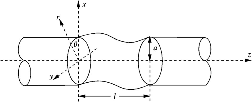
Consider the cylindrical shell model shown in Figure 1. The cylindrical shell of radius
The cylindrical shell model is meshed with quadrilateral elements. Figures 2A, B gives the meshing scheme with element number of 2112 and 8320, separately. Figure 3 provides the numerical solutions of the sound pressure at (
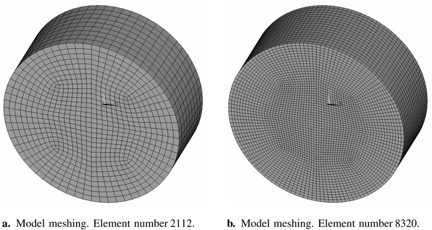
Figure 2. Meshing scheme for the cylindrical shell model with closed ends. Radius
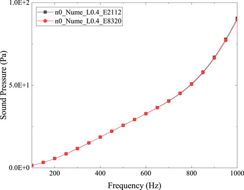
Figure 3. Numerical results of sound pressure at (
Consider the model presented in Figure 1. The cylindrical shell model for analytical analysis is of infinite length, in which only a segment of length
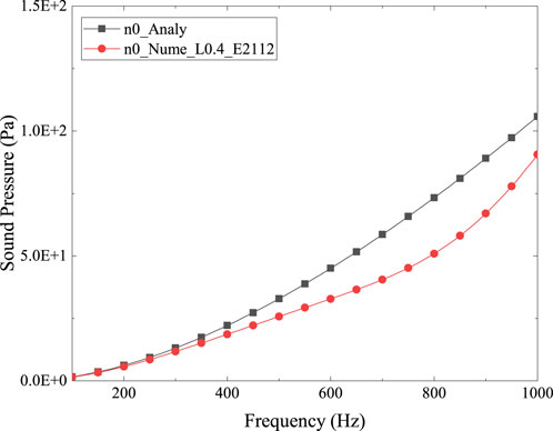
Figure 4. Numerical vs. analytical results of sound pressure at (
To reduce the computational errors resulting from the axial external space of the cylindrical shell, we attempt to lengthen the shell model with closed ends in the 3-D numerical analysis. For models of various lengths, the numerical results are compared with the analytical solution to determine an appropriate model configuration. Figure 5 gives the sound pressure at (
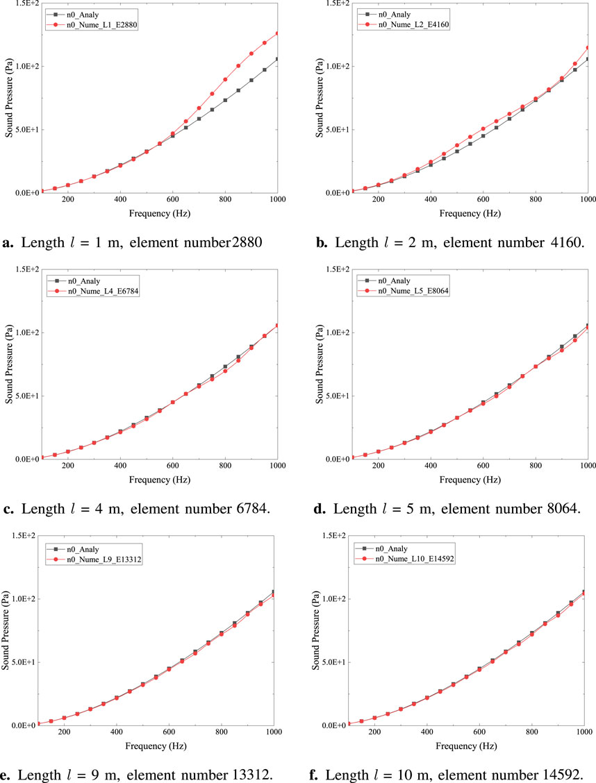
Figure 5. Numerical vs. analytical results of sound pressure at (
The data in Figures 5C–F, 6 give the relative error of the 3-D numerical solution to the analytical result. Similar characteristics are displayed by the four curves, namely, a rising relative error between the analytical and numerical solutions with increasing frequency, indicating that higher frequencies are more challenging to model accurately. This could be due to the higher spatial and temporal resolution required for capturing the dynamics of higher-frequency waves. For the cylindrical shell model of length
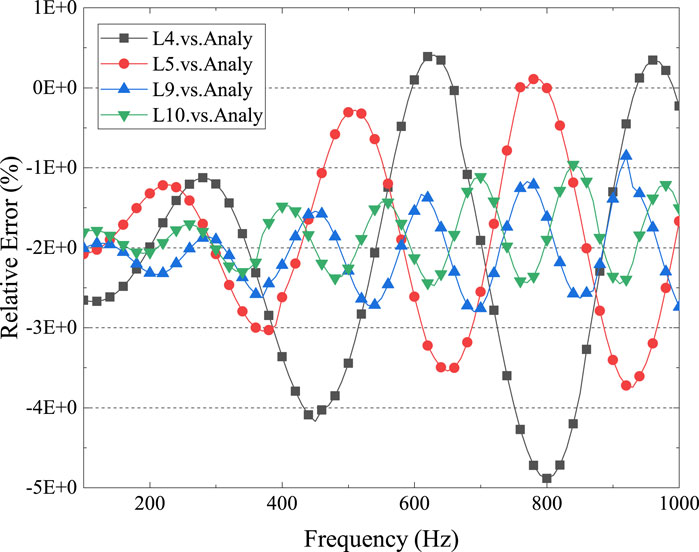
Figure 6. Relative error, numerical results vs. analytical results. Circumferential vibration order
Consider the cylindrical shell model shown in Figure 1. The cylindrical shell is closed at both ends for the 3-D numerical analysis. The radius
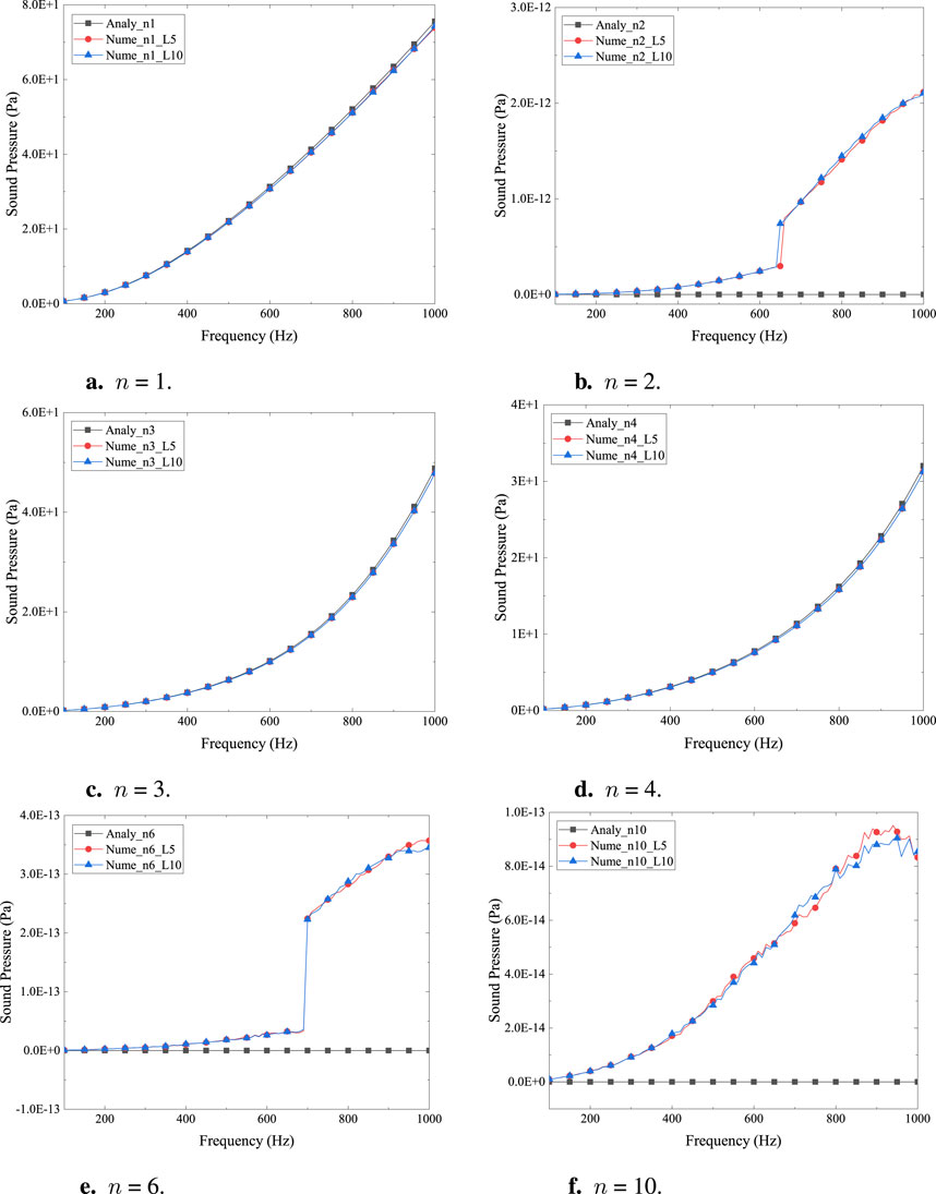
Figure 7. Sound pressure at (
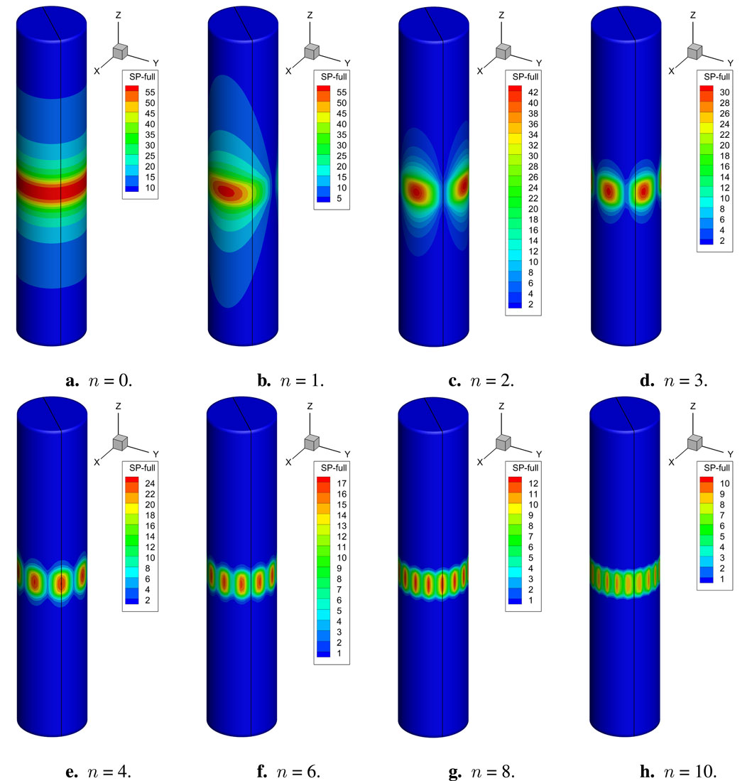
Figure 8. Numerical results. Sound pressure on the cylindrical shell with a length of 5 m. Frequency
Figure 7 shows that for n = 2, 6, and 10, the analytical solution goes to zero, and the numerical solution is less than 3.0E−12, which might be thought of as tending toward zero in numerical analysis. Note that the sound pressure at (
The agreement between analytical and numerical results for certain modes validates the theoretical model’s assumptions and the mathematical formulations that describe the sound pressure distribution. This is crucial for the reliability of predictions made using these models in practical applications. The results highlight the importance of considering different vibration modes in the analysis. The theoretical model predicts different behaviors for different modes, and the numerical simulations confirm these predictions, emphasizing the need for accurate modeling of vibration modes in the design and analysis of electric motors. The findings provide valuable insights for the design and optimization of electric motors, particularly in controlling the vibration modes that contribute to noise. Understanding which modes contribute to the sound pressure can guide the design of motor components to minimize noise emissions. The choice between analytical and numerical methods should be guided by the specific requirements of the problem, including the need for accuracy, computational resources, and the complexity of the model. The agreement between the two methods for certain modes suggests that, under these conditions, either method could be reliably used.
For the closed cylindrical shell model with a length of 5 m, Figures 8A–H provide the numerical sound pressure on the structure surface for various circumferential vibration orders, in which the frequency
5 Conclusion
This study concludes that the 3-D numerical analysis using FMBEM aligns well with the analytical solution for the sound pressure in the exterior acoustic domain of a cylindrical shell model, particularly when the model length is sufficient relative to its radius. The investigation reveals that computational accuracy improves as the model lengthens, suggesting a model length of at least 10 times the radius for accurate uncoupling analysis. The findings provide valuable insights for the design of low-noise motors and contribute to the understanding of electromagnetic vibration and noise control in electric motors.
Data availability statement
The original contributions presented in the study are included in the article/supplementary material; further inquiries can be directed to the corresponding author.
Author contributions
YX: conceptualization, investigation, methodology, project administration, and writing–original draft. JW: formal analysis, resources, supervision, and writing–review and editing. SY: data curation, validation, and writing–original draft. GL: software, visualization, and writing–review and editing. KZ: funding acquisition, validation, and writing–review and editing
Funding
The author(s) declare that financial support was received for the research, authorship, and/or publication of this article. The author(s) were sponsored by the Henan Provincial Key R&D and Promotion Project under Grant No. 232102220033, the National Natural Science Foundation of China under Grant No. 42207200, the Natural Science Foundation of Henan under Grant No. 222300420498, the Zhumadian 2023 Major Science and Technology Special Project under Grant No. ZMDSZDZX2023002, and the Postgraduate Education Reform and Quality Improvement Project of Henan Province under Grant No. YJS2023JD52.
Conflict of interest
The authors declare that the research was conducted in the absence of any commercial or financial relationships that could be construed as a potential conflict of interest.
Publisher’s note
All claims expressed in this article are solely those of the authors and do not necessarily represent those of their affiliated organizations, or those of the publisher, the editors, and the reviewers. Any product that may be evaluated in this article, or claim that may be made by its manufacturer, is not guaranteed or endorsed by the publisher.
References
1. Ballo F, Gobbi M, Mastinu G, Palazzetti R. Noise and vibration of permanent magnet synchronous electric motors: a simplified analytical model. IEEE Trans Transportation Electrification (2023) 9:2486–96. doi:10.1109/TTE.2022.3209917
2. Xing Z, Wang X, Zhao W, Sun L, Niu N. Calculation method for natural frequencies of stator of permanent magnet synchronous motors based on three-dimensional elastic theory. IEEE Trans Energy Convers (2021) 36:755–66. doi:10.1109/TEC.2020.3030042
3. Xing Z, Wang X, Zhao W. Fast calculation of electromagnetic vibration of surface-mounted pmsm considering teeth saturation and tangential electromagnetic force. IEEE Trans Ind Electronics (2024) 71:316–26. doi:10.1109/TIE.2023.3243298
4. Zhu S, Zhao W, Ji J, Liu G, Mao Y, Liu T. Investigation of bread-loaf magnet on vibration performance in fscw pmsm considering force modulation effect. IEEE Trans Transportation Electrification (2021) 7:1379–89. doi:10.1109/TTE.2020.3035180
5. Hong J, Wang S, Sun Y, Sun X, Cao H. Piecewise stagger poles with continuous skew edge for vibration reduction in surface-mounted pm synchronous machines. IEEE Trans Ind Electronics (2021) 68:8498–506. doi:10.1109/TIE.2020.3013535
6. Lin F, Zuo SG, Deng WZ, Wu SL. Reduction of vibration and acoustic noise in permanent magnet synchronous motor by optimizing magnetic forces. J Sound Vibration (2018) 429:193–205. doi:10.1016/j.jsv.2018.05.018
7. Hu S, Zuo S, Wu H, Liu M. An analytical method for calculating the natural frequencies of a motor considering orthotropic material parameters. IEEE Trans Ind Electronics (2019) 66:7520–8. doi:10.1109/TIE.2018.2883194
8. Torregrossa D, Peyraut F, Fahimi B, M’Boua J, Miraoui A. Multiphysics finite-element modeling for vibration and acoustic analysis of permanent magnet synchronous machine. IEEE Trans Energy Convers (2011) 26:490–500. doi:10.1109/TEC.2010.2080681
9. Zhao J, Wang Z, Liu H, Ning F, Hong X, Du J, et al. Modal analysis and structure optimization of permanent magnet synchronous motor. IEEE Access (2020) 8:151856–65. doi:10.1109/ACCESS.2020.3017679
10. Mercorelli P. Denoising and harmonic detection using nonorthogonal wavelet packets in industrial applications. J Syst Sci Complexity (2007) 20:325–43. doi:10.1007/s11424-007-9028-z
11. Mercorelli P. Detection of oscillations with application in the pantograph control. Recent Patents Electr Eng (2011) 4:71–7. doi:10.2174/1874476111104010071
12. Mercorelli P. A denoising procedure using wavelet packets for instantaneous detection of pantograph oscillations. Mech Syst Signal Process (2013) 35:137–49. doi:10.1016/j.ymssp.2012.09.001
13. Chai F, Li Y, Pei Y, Li Z. Accurate modelling and modal analysis of stator system in permanent magnet synchronous motor with concentrated winding for vibration prediction. IET Electric Power Appl (2018) 12:1225–32. doi:10.1049/iet-epa.2017.0813
14. Wu Z, Fan Y, Chen H, Wang X, Lee CHT. Electromagnetic force and vibration study of dual-stator consequent-pole hybrid excitation motor for electric vehicles. IEEE Trans Vehicular Technology (2021) 70:4377–88. doi:10.1109/TVT.2021.3075461
15. Park S, Kim W, Kim SI. A numerical prediction model for vibration and noise of axial flux motors. IEEE Trans Ind Electronics (2014) 61:5757–62. doi:10.1109/TIE.2014.2300034
16. Čorović S, Miljavec D. Modal analysis and rotor-dynamics of an interior permanent magnet synchronous motor: an experimental and theoretical study. Appl Sci (2020) 10:5881. doi:10.3390/app10175881
17. Mendizabal M, McCloskey A, Poza J, Zarate S, Iriondo J, Irazu L. Optimum slot and pole design for vibration reduction in permanent magnet synchronous motors. Appl Sci (2021) 11:4849. doi:10.3390/app11114849
18. Wang H, Williams K. Effects of laminations on the vibrational behaviour of electrical machine stators. J Sound Vibration (1997) 202:703–15. doi:10.1006/jsvi.1996.0845
19. Deng W, Zuo S. Axial force and vibroacoustic analysis of external-rotor axial-flux motors. IEEE Trans Ind Electronics (2018) 65:2018–30. doi:10.1109/TIE.2017.2739697
20. Xu X, Han Q, Qin Z, Chu F. Analytical methods for the radial electromagnetic vibration of stator in permanent magnet motors with an amorphous alloy core. Mech Syst Signal Process (2020) 145:106909. doi:10.1016/j.ymssp.2020.106909
21. Mao Y, Zhao W, Zhu S, Chen Q, Ji J. Vibration investigation of spoke-type pm machine with asymmetric rotor considering modulation effect of stator teeth. IEEE Trans Ind Electronics (2021) 68:9092–103. doi:10.1109/TIE.2020.3022530
22. Wang S, Hong J, Sun Y, Cao H. Mechanical and magnetic pivot roles of tooth in vibration of electrical machines. IEEE Trans Energy Convers (2021) 36:139–48. doi:10.1109/TEC.2020.3007802
23. Xing Z, Wang X, Zhao W, Wang F. Calculation of stator natural frequencies of electrical machines considering complex boundary conditions. IEEE Trans Industry Appl (2022) 58:7079–87. doi:10.1109/TIA.2022.3191301
24. Zhao G, Sun L, Niu N, Wang X, Xing Z. Analysis of vibration characteristics of stators of electrical machines under actual boundary. Mech Syst Signal Process (2023) 185:109778. doi:10.1016/j.ymssp.2022.109778
25. Sommerfeld A. Partial differential equations in physics. Academic Press (1949). v-vi. doi:10.1016/B978-0-12-654658-3.50003-3
26. Engleder OSS. Stabilized boundary element methods for exterior Helmholtz problems. Numerische Mathematik (2008) 110:145–60. doi:10.1007/s00211-008-0161-y
27. Chen L, Zhang Y, Lian H, Atroshchenko E, Ding C, Bordas S. Seamless integration of computer-aided geometric modeling and acoustic simulation: isogeometric boundary element methods based on catmull-clark subdivision surfaces. Adv Eng Softw (2020) 149:102879. doi:10.1016/j.advengsoft.2020.102879
28. Greengard L, Rokhlin V. A fast algorithm for particle simulations. J Comput Phys (1987) 73:325–48. doi:10.1016/0021-9991(87)90140-9
29. Coifman R, Rokhlin V, Wandzura S. The fast multipole method for the wave equation: a pedestrian prescription. IEEE Antennas Propagation Mag (1993) 35:7–12. doi:10.1109/74.250128
30. Rokhlin V. Diagonal forms of translation operators for the Helmholtz equation in three dimensions. Appl Comput Harmonic Anal (1993) 1:82–93. doi:10.1006/acha.1993.1006
31. Martinsson P, Rokhlin V. A fast direct solver for boundary integral equations in two dimensions. J Comput Phys (2005) 205:1–23. doi:10.1016/j.jcp.2004.10.033
32. Martinsson P, Rokhlin V. A fast direct solver for scattering problems involving elongated structures. J Comput Phys (2007) 221:288–302. doi:10.1016/j.jcp.2006.06.037
33. Bebendorf SMR. Adaptive low-rank approximation of collocation matrices. Computing (2003) 70:1–24. doi:10.1007/s00607-002-1469-6
34. Kim NH, Dong J. Shape sensitivity analysis of sequential structural-acoustic problems using FEM and BEM. J Sound Vibration (2006) 290:192–208. doi:10.1016/j.jsv.2005.03.013
35. Chen L, Zhao J, Lian H, Yu B, Atroshchenko E, Li P. A BEM broadband topology optimization strategy based on Taylor expansion and SOAR method-Application to 2D acoustic scattering problems. Int J Numer Methods Eng (2023) 124:5151–82. doi:10.1002/nme.7345
36. Qu Y, Zhou Z, Chen L, Lian H, Li X, Hu Z, et al. Uncertainty quantification of vibro-acoustic coupling problems for robotic manta ray models based on deep learning. Ocean Eng (2024) 299:117388. doi:10.1016/j.oceaneng.2024.117388
37. Simpson R, Bordas S, Trevelyan J, Rabczuk T. A two-dimensional isogeometric boundary element method for elastostatic analysis. Computer Methods Appl Mech Eng (2012) 209-212:87–100. doi:10.1016/j.cma.2011.08.008
38. Hughes T, Cottrell J, Bazilevs Y. Isogeometric analysis: CAD, finite elements, NURBS, exact geometry and mesh refinement. Computer Methods Appl Mech Eng (2005) 194:4135–95. doi:10.1016/j.cma.2004.10.008
39. Chen L, Lu C, Lian H, Liu Z, Zhao W, Li S, et al. Acoustic topology optimization of sound absorbing materials directly from subdivision surfaces with isogeometric boundary element methods. Computer Methods Appl Mech Eng (2020) 362:112806. doi:10.1016/j.cma.2019.112806
40. Shen X, Du C, Jiang S, Sun L, Chen L. Enhancing deep neural networks for multivariate uncertainty analysis of cracked structures by POD-RBF. Theor Appl Fracture Mech (2023) 125:103925. doi:10.1016/j.tafmec.2023.103925
41. Scott M, Simpson R, Evans J, Lipton S, Bordas S, Hughes T, et al. Isogeometric boundary element analysis using unstructured T-splines. Computer Methods Appl Mech Eng (2013) 254:197–221. doi:10.1016/j.cma.2012.11.001
42. Takahashi T, Matsumoto T. An application of fast multipole method to isogeometric boundary element method for Laplace equation in two dimensions. Eng Anal Boundary Elem (2012) 36:1766–75. doi:10.1016/j.enganabound.2012.06.004
43. Chen L, Cheng R, Li S, Lian H, Zheng C, Bordas S. A sample-efficient deep learning method for multivariate uncertainty qualification of acoustic-vibration interaction problems. Computer Methods Appl Mech Eng (2022) 393:114784. doi:10.1016/j.cma.2022.114784
44. Zhang S, Yu B, Chen L. Non-iterative reconstruction of time-domain sound pressure and rapid prediction of large-scale sound field based on ig-drbem and pod-rbf. J Sound Vibration (2024) 573:118226. doi:10.1016/j.jsv.2023.118226
45. Chen L, Lian H, Dong HW, Yu P, Jiang S, Bordas SP. Broadband topology optimization of three-dimensional structural-acoustic interaction with reduced order isogeometric FEM/BEM. J Comput Phys (2024) 509:113051. doi:10.1016/j.jcp.2024.113051
46. Chen L, Lian H, Pei Q, Meng Z, Jiang S, Dong HW, et al. FEM-BEM analysis of acoustic interaction with submerged thin-shell structures under seabed reflection conditions. Ocean Eng (2024) 309:118554. doi:10.1016/j.oceaneng.2024.118554
47. Cao G, Yu B, Chen L, Yao W. Isogeometric dual reciprocity bem for solving non-fourier transient heat transfer problems in fgms with uncertainty analysis. Int J Heat Mass Transfer (2023) 203:123783. doi:10.1016/j.ijheatmasstransfer.2022.123783
48. Ginnis A, Kostas K, Politis C, Kaklis P, Belibassakis K, Gerostathis T, et al. Isogeometric boundary-element analysis for the wave-resistance problem using T-splines. Computer Methods Appl Mech Eng (2014) 279:425–39. doi:10.1016/j.cma.2014.07.001
49. Zhang G, He Z, Qin J, Hong J. Magnetically tunable bandgaps in phononic crystal nanobeams incorporating microstructure and flexoelectric effects. Appl Math Model (2022) 111:554–66. doi:10.1016/j.apm.2022.07.005
50. Zhang G, He Z, Gao XL, Zhou H. Band gaps in a periodic electro-elastic composite beam structure incorporating microstructure and flexoelectric effects. Archive Appl Mech (2023) 93:245–60. doi:10.1007/s00419-021-02088-9
51. Chen L, Lian H, Xu Y, Li S, Liu Z, Atroshchenko E, et al. Generalized isogeometric boundary element method for uncertainty analysis of time-harmonic wave propagation in infinite domains. Appl Math Model (2023) 114:360–78. doi:10.1016/j.apm.2022.09.030
52. Zhang G, Gao X, Wang S, Hong J. Bandgap and its defect band analysis of flexoelectric effect in phononic crystal plates. Eur J Mechanics-A/Solids (2024) 104:105192. doi:10.1016/j.euromechsol.2023.105192
53. Zhang G, He Z, Wang S, Hong J, Cong Y, Gu S. Elastic foundation-introduced defective phononic crystals for tunable energy harvesting. Mech Mater (2024) 191:104909. doi:10.1016/j.mechmat.2024.104909
54. Shen X, Du C, Jiang S, Zhang P, Chen L. Multivariate uncertainty analysis of fracture problems through model order reduction accelerated SBFEM. Appl Math Model (2024) 125:218–40. doi:10.1016/j.apm.2023.08.040
55. Simpson R, Liu Z, Vázquez R, Evans J. An isogeometric boundary element method for electromagnetic scattering with compatible B-spline discretizations. J Comput Phys (2018) 362:264–89. doi:10.1016/j.jcp.2018.01.025
56. Qu Y, Jin F, Yang J. Temperature effects on mobile charges in thermopiezoelectric semiconductor plates. Int J Appl Mech (2021) 13:2150037. doi:10.1142/s175882512150037x
57. Xu Y, Li H, Chen L, Zhao J, Zhang X. Monte Carlo based isogeometric stochastic finite element method for uncertainty quantization in vibration analysis of piezoelectric materials. Mathematics (2022) 10:1840. doi:10.3390/math10111840
58. Qu Y, Zhang G, Gao X, Jin F. A new model for thermally induced redistributions of free carriers in centrosymmetric flexoelectric semiconductor beams. Mech Mater (2022) 171:104328. doi:10.1016/j.mechmat.2022.104328
59. Chen L, Wang Z, Lian H, Ma Y, Meng Z, Li P, et al. Reduced order isogeometric boundary element methods for CAD-integrated shape optimization in electromagnetic scattering. Computer Methods Appl Mech Eng (2024) 419:116654. doi:10.1016/j.cma.2023.116654
60. Li H, Chen L, Zhi G, Meng L, Lian H, Liu Z, et al. A direct fe2 method for concurrent multilevel modeling of piezoelectric materials and structures. Computer Methods Appl Mech Eng (2024) 420:116696. doi:10.1016/j.cma.2023.116696
61. Chen L, Liu C, Zhao W, Liu L. An isogeometric approach of two dimensional acoustic design sensitivity analysis and topology optimization analysis for absorbing material distribution. Computer Methods Appl Mech Eng (2018) 336:507–32. doi:10.1016/j.cma.2018.03.025
62. Xu G, Li M, Mourrain B, Rabczuk T, Xu J, Bordas SP. Constructing IGA-suitable planar parameterization from complex CAD boundary by domain partition and global/local optimization. Computer Methods Appl Mech Eng (2018) 328:175–200. doi:10.1016/j.cma.2017.08.052
63. Li S, Trevelyan J, Wu Z, Lian H, Wang D, Zhang W. An adaptive SVD-Krylov reduced order model for surrogate based structural shape optimization through isogeometric boundary element method. Computer Methods Appl Mech Eng (2019) 349:312–38. doi:10.1016/j.cma.2019.02.023
64. Chen L, Lian H, Liu Z, Chen H, Atroshchenko E, Bordas S. Structural shape optimization of three dimensional acoustic problems with isogeometric boundary element methods. Computer Methods Appl Mech Eng (2019) 355:926–51. doi:10.1016/j.cma.2019.06.012
65. Chen L, Lian H, Natarajan S, Zhao W, Chen X, Bordas S. Multi-frequency acoustic topology optimization of sound-absorption materials with isogeometric boundary element methods accelerated by frequency-decoupling and model order reduction techniques. Computer Methods Appl Mech Eng (2022) 395:114997. doi:10.1016/j.cma.2022.114997
66. Lu C, Chen L, Luo J, Chen H. Acoustic shape optimization based on isogeometric boundary element method with subdivision surfaces. Eng Anal Boundary Elem (2023) 146:951–65. doi:10.1016/j.enganabound.2022.11.010
67. Chen L, Lian H, Liu Z, Gong Y, Zheng C, Bordas S. Bi-material topology optimization for fully coupled structural-acoustic systems with isogeometric FEM-BEM. Eng Anal Boundary Elem (2022) 135:182–95. doi:10.1016/j.enganabound.2021.11.005
Keywords: electromagnetic vibration, acoustic analysis, electric motors, fast multipole boundary element method, permanent magnet synchronous motors
Citation: Xu Y, Wang J, Yang S, Lei G and Zhao K (2024) Acoustic analysis of a three-dimensional cylindrical shell model under electromagnetic vibration. Front. Phys. 12:1468327. doi: 10.3389/fphy.2024.1468327
Received: 21 July 2024; Accepted: 09 October 2024;
Published: 12 November 2024.
Edited by:
Leilei Chen, Huanghuai University, ChinaReviewed by:
Lu Meng, Taiyuan University of Technology, ChinaKui Liu, Harbin Institute of Technology, China
Paolo Mercorelli, Leuphana University Lüneburg, Germany
Copyright © 2024 Xu, Wang, Yang, Lei and Zhao. This is an open-access article distributed under the terms of the Creative Commons Attribution License (CC BY). The use, distribution or reproduction in other forums is permitted, provided the original author(s) and the copyright owner(s) are credited and that the original publication in this journal is cited, in accordance with accepted academic practice. No use, distribution or reproduction is permitted which does not comply with these terms.
*Correspondence: Kuanyao Zhao, a3kuemhhb0BodWFuZ2h1YWkuZWR1LmNu
 Yanming Xu
 Jiachen Wang
 Sen Yang1,2