- 1 Ocean Engineering Research Center, Hangzhou Dianzi University, Hangzhou, China
- 2 School of Mecharical Engineering, Hangzhou Dianzi University, Hangzhou, China
Introduction: Orthogonal Frequency Division Multiplexing (OFDM) is widely recognized for its high efficiency in modulation techniques and has been extensively applied in underwater acoustic communication. However, the unique sparsity and noise interference characteristics of the underwater channel pose significant challenges to the performance of traditional channel estimation methods.
Methods: To address these challenges, we propose a sparse underwater channel estimation method that combines the Noise2Noise (N2N) algorithm with the Sparsity Adaptive Matching Pursuit (SAMP) algorithm. This novel approach integrates the N2N technique from image denoising theory with the SAMP algorithm, utilizing a constant iteration termination threshold that does not require prior information. The method leverages the U-net neural network structure to denoise noisy pilot signals, thereby restoring channel sparsity and enhancing the accuracy of channel estimation.
Results: Simulation results indicate that our proposed method demonstrates commendable channel estimation performance across various signal-to-noise ratio (SNR) conditions. Notably, in low SNR environments, the N2N-SAMP algorithm significantly outperforms the traditional SAMP algorithm in terms of Mean Squared Error (MSE) and Bit Error Rate (BER). Specifically, at SNR levels of 0 dB, 10 dB, and 20 dB, the MSE of channel estimation is reduced by 58.95%, 76.08%, and 19.42%, respectively, compared to the SAMP algorithm that selects the optimal threshold based on noise power. Furthermore, the system’s BER is decreased by 12.35%, 26.41%, and 29.62%, respectively.
Discussion: The findings suggest that the integration of N2N and SAMP algorithms offers a promising solution for improving channel estimation in underwater communication channels, especially under low SNR conditions. The significant reduction in MSE and BER highlights the effectiveness of our proposed method in enhancing the reliability and accuracy of underwater communication systems.
1 Introduction
In the process of ocean exploration and development, underwater acoustic communication technology plays an essential role. It is not only a bridge for marine resource development and marine environmental monitoring but also an important part of maritime safety and national defense. Currently, underwater communication faces many challenges, especially in the complex and variable underwater environment where the stability and reliability of signal transmission are tested [1–3]. OFDM technology has been widely applied in underwater communication systems due to its excellent ability to resist multipath interference and its efficient spectral utilization efficiency [4, 5]. However, the performance of OFDM technology largely depends on the accuracy of channel estimation. In the underwater environment, the channel exhibits significant sparsity, meaning that the signal energy is mainly concentrated on a few paths, which brings new opportunities and challenges for channel estimation.
Traditional channel estimation methods, such as the Least Squares (LS) method [6] and the Minimum Mean Square Error (MMSE) method [7], encounter performance bottlenecks when dealing with sparse channels. These methods often require a large number of pilot signals, leading to the waste of spectral resources and potentially reducing estimation accuracy due to noise interference. The introduction of Compressed Sensing (CS) theory has provided a novel solution for sparse channel estimation [8, 9]. Utilizing the sparsity of signals, CS theory enables high-precision signal reconstruction from a small number of observation samples, thereby reducing the need for pilot signals and improving spectral utilization [10].
The problem of underwater channel estimation based on CS is essentially the process of reconstructing sparse signals. The reconstruction algorithms can be primarily divided into two major categories: those based on convex optimization theory [11] and those based on the greedy algorithm concept [10]. Convex optimization algorithms offer high precision in the reconstruction of sparse signals, with Basis Pursuit (BP) [12] being a quintessential example of such an algorithm. Greedy algorithms have garnered significant attention due to their lower computational complexity and ease of implementation. Typical greedy algorithms include: Orthogonal Matching Pursuit (OMP) [13], generalized Orthogonal Matching Pursuit (gOMP) [14], Compressive Sampling Matching Pursuit (CoSaMP) [15], and the SAMP algorithm [16], among others. Berger et al. [17] utilized the OMP algorithm to achieve channel estimation for multi-carrier underwater acoustic systems. The experimental results indicated that in cases where the channel is indeed sparse, the OMP algorithm outperforms the LS algorithm, which is based on the assumption of a dense channel. Huang et al. [11] compared the computational complexity and channel estimation accuracy of three typical BP algorithms and the OMP algorithm in OFDM underwater communication systems through both simulation and real-data experiments. The experiments demonstrated that the channel estimation performance of the three BP algorithms was superior to that of the OMP algorithm; however, their computational complexity was higher than that of the OMP algorithm.
In the field of compressed sensing, the SAMP algorithm overcomes the challenges of traditional algorithms by adaptively adjusting the step size of atom selection, without the need to predetermined sparsity, thereby enhancing the flexibility and accuracy of signal reconstruction [18]. However, the performance of the SAMP algorithm in underwater channel estimation may still be significantly affected by noise. Determining an appropriate iteration termination threshold is crucial for the accuracy of the algorithm, but setting this threshold becomes complex in the presence of noise. Under ideal conditions, the iteration termination threshold can be set to a very small value close to zero, allowing the algorithm to closely approximate the true sparsity [19]. The interference of noise makes it difficult to achieve this ideal threshold, thereby affecting the accuracy of channel estimation.
Additionally, the SAMP algorithm is highly sensitive to noise and heavily reliant on prior information such as the SNR when setting the iteration termination threshold, which limits its practicality in dynamic underwater acoustic environments [20]. The noise in the marine environment is characterized by its complexity and variability, which sets higher demands for the robustness of channel estimation algorithms. To overcome these limitations, it is essential to design a new algorithm that can adapt to changes in the noise environment without relying on the SNR or other prior information.
In response to the aforementioned challenges, this study proposes an innovative N2N-SAMP method for sparse underwater acoustic channel estimation. This approach integrates the N2N denoising technique [21] with the SAMP algorithm, eliminating the need for prior information such as SNR and featuring a constant iteration termination threshold. By designing a U-net neural network suitable for denoising pilot signals, the algorithm presented in this paper can effectively filter out noise interference, restore the channel’s sparsity, and enhance the accuracy of channel estimation.
The organizational structure of this paper is as follows: The second section introduces the OFDM underwater communication system model; the third section elaborates on the standard SAMP and the N2N-SAMP method proposed in this paper; the fourth section demonstrates the performance of the method through simulation experiments; finally, the fifth section summarizes the entire paper.
2 System model
In the OFDM architecture, the original high data rate serial data stream is first converted into multiple low data rate parallel data streams to reduce the risk of inter-symbol interference (ISI) and inter-carrier interference (ICI). Subsequently, the data is allocated to a set of orthogonal subcarriers through an inverse fast fourier transform (IFFT), further optimizing the spectral efficiency. To further mitigate the effects of ISI and ICI, guard intervals (GI) and cyclic prefixes (CP) are inserted between OFDM symbols [22].
Upon reaching the receiver, the signal effectively restores the original serial data stream through steps such as performing a fast fourier transform (FFT), parallel-to-serial conversion, and demodulation. These steps ensure the accurate transmission and reception of data, thereby achieving efficient OFDM acoustic communication.
This section will introduce the OFDM acoustic channel model and the acoustic channel model based on compressed sensing theory, respectively.
2.1 Underwater acoustic channel model
Taking an OFDM underwater communication system with a subcarrier number
where
where
where
where
2.2 Underwater acoustic channel model based on compressed sensing
According to the theory of compressed sensing, let the original signal be
where
where
3 N2N-SAMP
Given the sparsity characteristic of the underwater acoustic channel, the SAMP algorithm is commonly used for channel estimation due to its effectiveness in reconstructing sparse signals. In this section, we analyze the bottleneck of the SAMP channel estimation algorithm and find that it is highly sensitive to noise, with its performance heavily impacted by noise interference. Additionally, the determination of its iterative stopping threshold is highly dependent on prior information such as SNR. To address these issues, we propose an N2N-SAMP algorithm that does not require prior information like SNR and features a constant iterative stopping threshold. By filtering out noise from the pilot signals, this method ensures the accuracy of channel reconstruction and reduces reliance on prior information such as SNR.
3.1 Standard SAMP algorithm bottleneck
In the Compressed Sensing domain, the sparsity of a signal is essential for the reconstruction process. Conventional reconstruction algorithms necessitate prior knowledge of the signal’s sparsity, which is often not known in real-world scenarios. The SAMP algorithm addresses this issue by adaptively adjusting the step size for atom selection, thus removing the need to preset sparsity, and consequently improving the flexibility and accuracy of signal reconstruction.
Despite the advantages of the SAMP algorithm, its performance in underwater channel estimation can still be significantly affected by noise. Determining an appropriate iteration termination threshold
Considering that noise can affect the performance of the SAMP channel estimation algorithm, Equation 4 can be rewritten as shown in Equation 8:
where
Figure 1 illustrates the equivalent time-domain discrete channel response
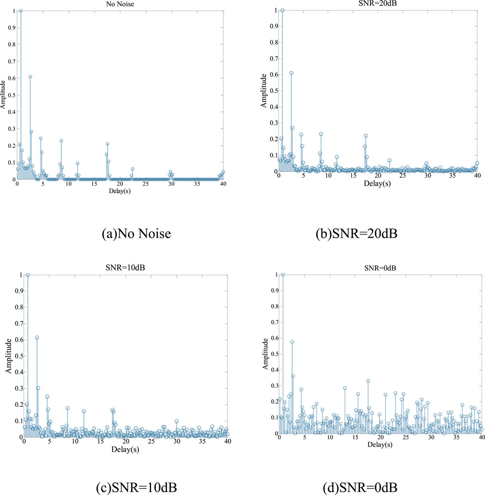
Figure 1. Equivalent time-domain discrete channel response under different noise levels. (A) No Noise (B) SNR=20dB (C) SNR=10dB (D) SNR=0dB.
Noise levels have a significant impact on the sparsity of the underwater acoustic channel. Under low noise conditions, the channel maintains good sparsity, and a smaller iterative termination threshold can be used to more accurately approximate the true channel impulse response. However, as noise power increases, the sparsity of the channel gradually decreases, necessitating an increase in the threshold to prevent mistakenly identifying noise as a genuine part of the channel.
To achieve effective channel estimation under various noise environments, the iterative termination threshold of the SAMP algorithm should be dynamically adjusted based on real-time noise power, which typically relies on prior information such as the SNR. An effective strategy is to reduce the impact of noise through denoising processing, restoring the noise-affected equivalent time-domain channel response
3.2 The principle of N2N denoising
Traditional image denoising models often utilize a vast collection of image pairs, each comprising a noisy image
where
Assuming a set of room temperature measurements
Training a neural network can be regarded as an extension of point estimation, where the objective is to train a neural network to output an expected value of
By continuously optimizing each image pair
where
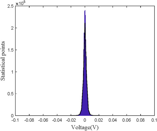
To verify whether the noise in the marine environment meets the zero-mean assumption required by the N2N denoising method, a statistical analysis of the collected marine noise data was conducted. The marine noise data originated from a South China Sea trial experiment conducted in August 2023, where continuous marine noise observation was carried out for 15 days in the South China Sea.
Figure 2 presents the results of this analysis, where the histogram depicts the cumulative counts of different voltage values, and the black curve represents the estimated probability density function based on these sample data. It is clear that the probability density function exhibits symmetry about the voltage zero value, which distinctly indicates that the frequency of occurrence of positive and negative directions in marine noise is balanced. In other words, positive and negative deviations are mutually balanced in the overall distribution, thereby confirming the zero-mean property of marine noise and ensuring the effectiveness of the N2N denoising method.
3.3 design of N2N denoising neural network
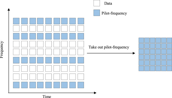
In OFDM underwater communication, each frame of the signal received by the receiver can be regarded as a two-dimensional matrix. It corresponds to each OFDM symbol in the time domain and to the frequencies of each subcarrier in the frequency domain, as shown in Figure 3. Accordingly, the pilot signals are also presented in matrix form. Therefore, the denoising process for the pilot signals can be considered as a matrix denoising problem. The essence of image denoising is also to process the pixel values in a two-dimensional matrix to remove or reduce the impact of noise, thereby restoring the original noise-free image. Given the inherent correlation between image denoising and pilot signal denoising, the denoising process for pilot signals can be equivalent to image denoising.
To address the challenge of denoising pilot signals, this study employs an innovative N2N denoising approach. This method does not require noise-free reference signals but achieves effective noise suppression through training with pairs of noisy images. Given the difficulty of obtaining noise-free pilot signals in underwater communication systems and the zero-mean characteristic of oceanic noise, the N2N denoising technique offers a practical solution for the denoising of pilot matrices.
In the N2N-SAMP method designed in this study, the U-net network model is selected. The structure of this model can be divided into four core parts: down-sampling, up-sampling, skip connections, and the output section. The down-sampling part, composed of consecutive convolutional layers and pooling layers, is specifically responsible for extracting key features from the input image. The up-sampling part then enlarges the size of the feature maps through transposed convolutions, thereby restoring the original size of the image. Skip connections link the corresponding layers of the down-sampling and up-sampling parts to facilitate feature transfer. The U-net network, with its powerful feature extraction capabilities, can more deeply understand the content of the image and accurately restore the parts of the image contaminated by noise.
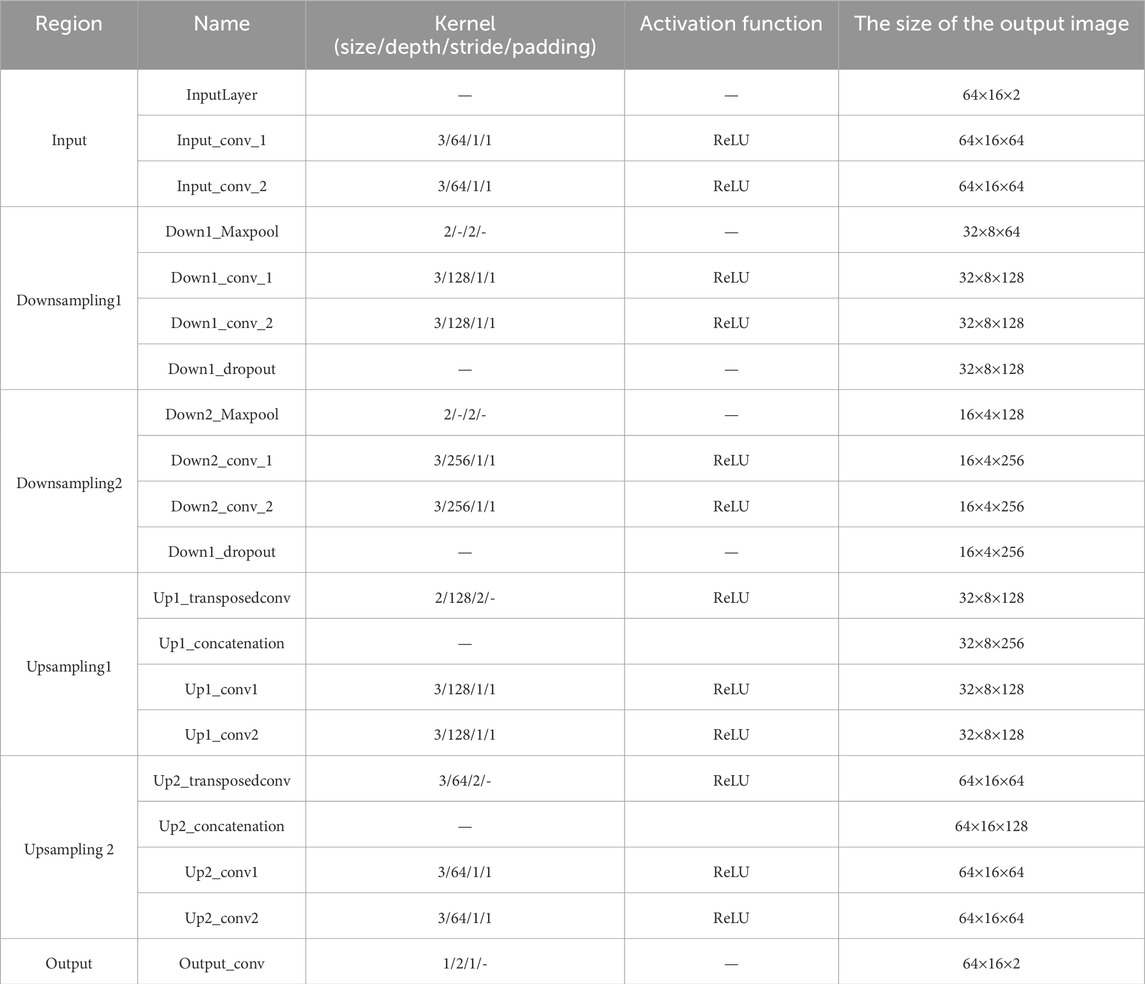
In the simulation experiments of this study, the number of pilots is 64, and a frame of data contains 16 OFDM symbols. The received pilot signals are complex-valued matrices. Since general neural networks cannot directly process complex numbers, the received pilot matrix is divided into real and imaginary parts, corresponding to two channels of an image. Furthermore, to adapt to the size and characteristics of the pilot matrix, the network structure of U-Net has been adjusted accordingly.
Figure 4 illustrates the schematic diagram of the U-Net network structure employed in this paper. The left half of the network structure consists of an input module and two downsampling modules, which are responsible for extracting features from the input pilot matrix; the right half is composed of two upsampling modules and an output module, which are tasked with restoring a clear pilot matrix based on the extracted features. Skip connections are used between each level for information transfer and fusion. The input module includes an image input layer and two convolutional layers for preliminary processing of the input pilot matrix. Each downsampling module contains a max pooling layer and two convolutional layers for stepwise feature extraction and abstraction. To prevent overfitting, a Dropout layer is added after each downsampling module, which randomly sets the output of a portion of the input neurons to zero. The upsampling modules gradually restore the size of the pilot and refine the features through transposed convolutional layers, feature concatenation layers, and convolutional layers. The output module consists of a convolutional layer that outputs the final denoised result. Except for the last convolutional layer, a ReLU activation function is added after each convolutional layer to enhance the network’s nonlinear expressive power. The specific parameters of the U-Net network are detailed in Table 1.
3.4 Procedure of the proposed N2N-SAMP
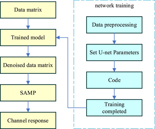
Based on the designed denoising neural network architecture, the following sections provide a detailed introduction to the N2N-SAMP method proposed in this study. The algorithmic process is illustrated in the Figure 5 and is primarily divided into two steps: training the denoising neural network and utilizing the denoised data for channel estimation.
The first phase of this method involves generating OFDM reception data by utilizing a simulated underwater acoustic channel model and adding zero-mean noise at different SNR. Subsequently, the received data undergoes preprocessing to extract the noisy pilot signals matrix and process them into a complex-valued pilot matrix.With the noisy pilot data required for training, the U-net network can be trained. The loss function used for this network is the
where
After the model is trained, the network is evaluated using a test set to obtain the denoised pilot matrices. The denoised pilot signals are then used in conjunction with the SAMP algorithm for channel estimation. At this point, the channel reconstructed by SAMP is the denoised equivalent time-domain underwater acoustic channel response, which is sparser than the original noisy channel, and the reconstruction accuracy can be effectively improved. Since the denoising process reduces noise, a smaller iterative termination threshold can be set without the need for dynamic adjustment based on the noise power.
4 Results and analysis
In this section, we will provide a detailed description of the simulation experiment setup used to verify the performance of the proposed N2N-SAMP algorithm. Initially, we will introduce the constructed underwater acoustic channel model, including its parameter selection and model characteristics. Subsequently, we will present the training results of the U-net network. Finally, this section will showcase the performance of the N2N-SAMP algorithm under different SNR conditions.
4.1 Simulation model construction
The initial stage of the study involves the simulation of an underwater acoustic channel model to obtain the necessary characteristics of the underwater channel. This study utilizes the underwater acoustic channel model developed in Ref. [23], which has been proven effective through numerous at-sea experiments. The model not only takes into account the fundamental physical laws of acoustic propagation but also considers the impact of random local displacements. It provides a more comprehensive and accurate description of the underwater acoustic channel, aiding in a deeper understanding of its characteristics and offering a crucial basis for the design, optimization, and performance evaluation of underwater acoustic communication systems.
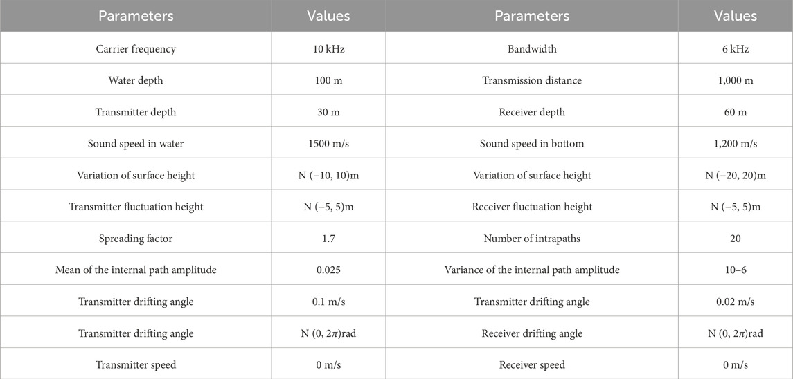
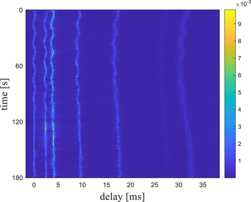
Underwater acoustic channel parameters are presented in Table 2. The center frequency of the transmitted signal is 10 kHz, with a bandwidth of 6 kHz and a signal duration of 60 s. The simulation results in a time-varying underwater acoustic channel as depicted in Figure 6. The underwater acoustic channel exhibits significant sparsity, with its energy primarily concentrated in seven multipath components. The maximum multipath delay reaches 32 ms, and there is a distinct time-varying characteristic that changes with the observation time.
After constructing the underwater acoustic channel, it is necessary to design the arrangement of pilot tones. In channel estimation based on CS, a pilot matrix composed of uniformly placed pilots does not achieve the best estimation performance. In this paper, a random pilot design method is selected, where the pilot positions corresponding to the smallest cross-correlation values of the sensing matrix are chosen from a certain number of randomly generated pilot positions. The specific implementation process of this method is as follows:
1. Initialize the parameters:
2. Randomly generate
3. Calculate the cross-correlation value corresponding to
4.
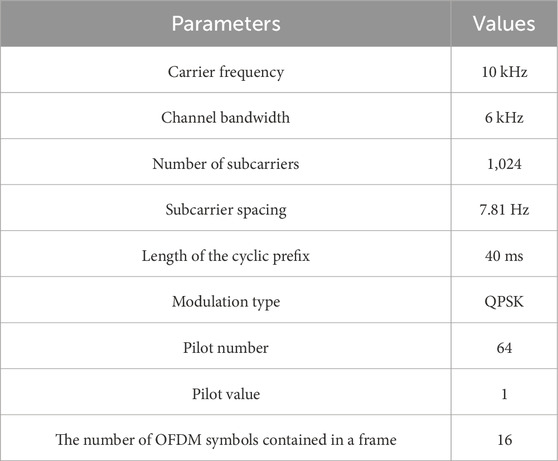
After obtaining the required underwater acoustic channel and pilot positions, OFDM underwater communication system simulations can be conducted to obtain pilot data under different SNR conditions. The simulation parameters for the OFDM underwater system are shown inTable 3.
4.2 Denoising performance
Under the condition of a signal-to-noise ratio (SNR) ranging from 0 dB to 20 dB, 20,000 frames of pilot complex matrix data with zero-mean noise were generated using an underwater acoustic channel simulation model. These complex matrices are then transformed into two-channel image data. Since training the network requires pairs of noisy images, after obtaining the dataset of noisy pilots, 80% of the data is used as the training set, and 20% as the test set. Finally, the U-Net network is trained using the Adam optimization algorithm, with a maximum of 300 training epochs. The dataset is shuffled after each training epoch. The initial learning rate is set to 0.01, and the learning rate decay factor is 0.1. After 200 epochs, the learning rate begins to decrease, ultimately reaching a very low level for the loss function value.
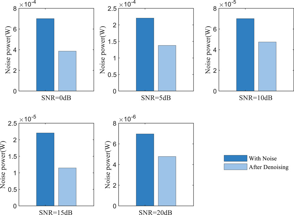
To verify the effectiveness of the denoiser in removing noise, the noise energy contained in the pilot matrix before and after denoising was statistically analyzed. Figure 7 presents a comparison of noise energy before and after denoising the pilot matrix at SNR levels of 0, 5, 10, 15, and 20 dB. It is evident from the figure that the denoiser effectively reduces the noise in the received pilot matrix. After calculation, it was found that over the range of SNR from 0 to 20 dB, the noise energy was reduced by more than 50%. Specifically, at an SNR of 20 dB, the least noise reduction of 52.66% was observed, while at an SNR of 15 dB, the maximum noise reduction of 69.82% was achieved, indicating the best denoising effect. This experiment demonstrates that the N2N algorithm can effectively reduce noise interference in the pilot, laying the foundation for subsequent sparse underwater channel reconstruction.
4.3 Simulation results
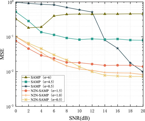
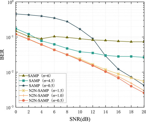
To verify the channel estimation performance of the N2N-SAMP algorithm and the impact of the iterative threshold on the algorithm, channel estimations are conducted using SAMP and N2N-SAMP with different threshold values
From Figure 8, it is evident that the SAMP algorithm is highly unstable, and the choice of
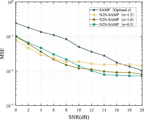
To further validate the performance of N2N-SAMP, during the experimental process, the parameter
From Figure 10, it can be observed that when
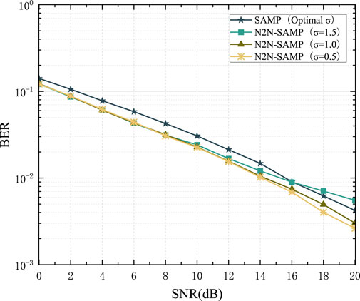
Figure 11 presents a comparison of the BER for the OFDM system. It is evident from the figure that the N2N-SAMP algorithm also demonstrates superiority in terms of system BER. Specifically, when
5 Conclusion
In response to the issue that the performance of the traditional SAMP sparse underwater channel estimation algorithm largely depends on the choice of its iterative stopping threshold, and that the optimal threshold varies significantly under different noise power conditions, this paper conducts a study on sparse underwater channel estimation in OFDM underwater communication systems. The paper first introduces the N2N algorithm from image denoising theory and combines it with the SAMP algorithm to propose an N2N-SAMP sparse underwater channel estimation method that does not require prior information such as SNR and has a constant iterative stopping threshold. The denoising problem of the pilot signal is transformed into an image denoising problem, and considering the statistical characteristics of oceanic noise, a U-net neural network suitable for pilot signal input is designed in conjunction with the N2N algorithm. Simulation experiments are conducted to verify the correctness and effectiveness of the proposed method. In subsequent work, sea trials are needed to further verify this algorithm in a real marine environment.
Data availability statement
The raw data supporting the conclusions of this article will be made available by the authors, without undue reservation.
Author contributions
ZW: Data curation, Methodology, Visualization, Writing–original draft. MW: Data curation, Visualization, Writing–review and editing. YW: Data curation, Methodology, Software, Writing–original draft. ZZ: Writing–review and editing. GS: Writing–review and editing. JZ: Writing–review and editing. NH: Writing–review and editing.
Funding
The author(s) declare that no financial support was received for the research, authorship, and/or publication of this article.
Conflict of interest
The authors declare that the research was conducted in the absence of any commercial or financial relationships that could be construed as a potential conflict of interest.
Publisher’s note
All claims expressed in this article are solely those of the authors and do not necessarily represent those of their affiliated organizations, or those of the publisher, the editors and the reviewers. Any product that may be evaluated in this article, or claim that may be made by its manufacturer, is not guaranteed or endorsed by the publisher.
References
1. Li Y, Zhang Y, Li W, Jiang T. Marine wireless big data: efficient transmission, related applications, and challenges. IEEE Wireless Commun (2018) 25(1):19–25. doi:10.1109/mwc.2018.1700192
2. Huang D, Zhao D, Wei L, Wang Z, Du Y. Modeling and analysis in marine big data: advances and challenges. Math Probl Eng (2015) 2015:1–13. doi:10.1155/2015/384742
3. Felemban E, Shaikh FK, Qureshi UM, Sheikh AA, Qaisar SB. Underwater sensor network applications: a comprehensive survey. Int J Distributed Sensor Networks (2015) 11(11):896832. doi:10.1155/2015/896832
4. Han X, Yin J, Du P, Guo X. The application of differential spread spectrum technology in underwater acoustic communication. The J Acoust Soc America (2012) 132(3_Suppl. ment):2015. doi:10.1121/1.4755457
5. Li Y, Wang S, Jin C, Zhang Y, Jiang T. A survey of underwater magnetic induction communications: fundamental issues, recent advances, and challenges. IEEE Commun Surv and Tutorials (2019) 21(3):2466–87. doi:10.1109/comst.2019.2897610
6. Van De Beek JJ, Edfors O, Sandell M, Wilson SK, Börjesson PO. On channel estimation in OFDM systems[C]//1995 IEEE 45th vehicular technology conference. Countdown to the wireless twenty-first century, 2. IEEE (1995). p. 815–9.
7. Ozdemir M, Arslan H. Channel estimation for wireless OFDM systems. IEEE Commun Surv Tutorials (2007) 9(2):18–48. doi:10.1109/comst.2007.382406
8. Berger CR, Wang Z, Huang J, Zhou S. Application of compressive sensing to sparse channel estimation. IEEE Commun Mag (2010) 48(11):164–74. doi:10.1109/mcom.2010.5621984
9. Tropp JA. Greed is good: algorithmic results for sparse approximation. IEEE Trans Inf Theor (2004) 50(10):2231–42. doi:10.1109/tit.2004.834793
10. Fuchs JJ, Delyon B. Minimal L/sub 1/-norm reconstruction function for oversampled signals: applications to time-delay estimation. IEEE Trans Inf Theor (2000) 46(4):1666–73. doi:10.1109/18.850713
11. Huang J, Berger CR, Zhou S, Huang J. Comparison of basis pursuit algorithms for sparse channel estimation in underwater acoustic OFDM[C]//OCEANS'10 IEEE SYDNEY. IEEE (2010).
12. Kim SJ, Koh K, Lustig M, Boyd SP, Gorinevsky DM. An interior-point method for large-scale $\ell_1 $-regularized least squares. IEEE Journal Selected Topics Signal Processing (2007) 1(4):606–17. doi:10.1109/JSTSP.2007.910971
13. Tropp JA, Gilbert AC. Signal recovery from random measurements via orthogonal matching pursuit. IEEE Trans Inf Theor (2007) 53(12):4655–66. doi:10.1109/tit.2007.909108
14. Wang J, Kwon S, Shim B. Generalized orthogonal matching pursuit. IEEE Trans signal Process (2012) 60(12):6202–16. doi:10.1109/TSP.2012.2218810
15. Needell D, Tropp JA. CoSaMP: iterative signal recovery from incomplete and inaccurate samples. Appl Comput harmonic Anal (2009) 26(3):301–21. doi:10.1016/j.acha.2008.07.002
16. Do TT, Gan L, Nguyen N, Tran TD. Sparsity adaptive matching pursuit algorithm for practical compressed sensing[C]. In: 2008 42nd Asilomar conference on signals, systems and computers. IEEE (2008) p. 581–7.
17. Berger CR, Zhou S, Preisig JC, Willett PK. Sparse channel estimation for multicarrier underwater acoustic communication: from subspace methods to compressed sensing. IEEE Transactions Signal Processing (2009) 58(3):1708–21. doi:10.1109/TSP.2009.2038424
18. Yu Z. Variable step-size compressed sensing-based sparsity adaptive matching pursuit algorithm for speech reconstruction[C]. In: Proceedings of the 33rd Chinese control conference. IEEE (2014) p. 7344–9.
19. Yanwan Z, Yongjun Z, Bing S. A modified sparsity adaptive matching pursuit algorithm. Signal Process. (2012) 28(1):80–6. doi:10.1016/j.sigpro.2011.12.014
20. Zhou Y, Zeng FZ, Gu YC. A gradient descent sparse adaptive matching pursuit algorithm based on compressive sensing[C]//2016. Int Conf Machine Learn Cybernetics (Icmlc) (2016) 1:464–9. doi:10.1109/ICMLC.2016.7747983
21. Lehtinen J, Munkberg J, Hasselgren J, Laine S, Karras T, Aittala M, et al. Noise2Noise: learning image restoration without clean data. arXiv preprint arXiv:1803.04189 (2018). doi:10.48550/arXiv.1803.04189
22. Song A, Stojanovic M, Chitre M. Editorial underwater acoustic communications: where we stand and what is next? IEEE J Oceanic Eng (2019) 44(1). doi:10.1109/JOE.2018.2883872
Keywords: OFDM, underwater acoustic communication, SAMP, Noise2Noise (N2N), U-net
Citation: Wang Z, Wang M, Wang Y, Zhu Z, Shang G, Zhao J and Hu N (2024) Based on the N2N-SAMP for sparse underwater acoustic channel estimation. Front. Phys. 12:1460388. doi: 10.3389/fphy.2024.1460388
Received: 06 July 2024; Accepted: 26 November 2024;
Published: 17 December 2024.
Edited by:
Qingbo He, Shanghai Jiao Tong University, ChinaReviewed by:
Sunita Khichar, Chulalongkorn University, ThailandXiaoxi Ding, Chongqing University, China
Copyright © 2024 Wang, Wang, Wang, Zhu, Shang, Zhao and Hu. This is an open-access article distributed under the terms of the Creative Commons Attribution License (CC BY). The use, distribution or reproduction in other forums is permitted, provided the original author(s) and the copyright owner(s) are credited and that the original publication in this journal is cited, in accordance with accepted academic practice. No use, distribution or reproduction is permitted which does not comply with these terms.
*Correspondence: Maofa Wang, d2FuZ21mMTYwMEAxNjMuY29t
 Zhen Wang
 Maofa Wang1*
 Zhenjing Zhu
 Guangtao Shang
 Ning Hu