- School of Physics, Xidian University, Xi’an, China
The Bessel beams scattering of the fog particles were calculated by using the plane beams angle spectrum expansion method, and the effects of the topological charge and the half-conic angle of the Bessel beam on the differential scattering cross-section were analyzed by numerical calculation. Based on the scattering results of a single fog particle by a Bessel beam, by Monte Carlo method, the propagation characteristics of the Bessel beam in fogs with different visibility are simulated, and the effects of the wavelength, topological charge and semi-conic angle of the Bessel beam on transmissivity and reflectivity are analyzed. The studies show the self-healing ability of the Bessel beams, and the propagation distance of the Bessel beam is longer than that of the plane beams in fogs.
1 Introduction
In 1987, Durnin [1] proposed an exact nonsingular solution to the scalar wave equation of a non-diffractive beam, i.e., a zero-order Bessel beam, and pointed out that the intensity pattern of the transverse plane of this beam does not change when it propagating in free space. Durnin’s proposal and experiment on non-diffractive beams, i.e., zero-order Bessel beams, have aroused the interest of many researchers in the study of Bessel beams. Gori et al. [2] proposed a set of solutions to the paraxial wave equation, which modulates the Gaussian beams to obtain an approximation of Bessel beams, which is called zero-order Bessel-Gaussian beams, which makes experimental studies of almost diffraction-free beam propagation possible. In 1991, Mishra [3] carried out a vector wave analysis of a zero-order Bessel beam satisfying Maxwell’s equations by means of the Lorentz gauge, and compared it with scalar wave theory, pointed out the limitations of scalar wave theory, and introduced a modification of vector wave properties. In 2002, Garces-Chavez et al. [4] demonstrated that higher-order Bessel beams have orbital angular momentum (OAM) and demonstrated the transparent particles captured by OAM transferred from the beam to optical tweezers, which showed that Bessel beams have good practical value in the field of optical tweezers. In 2011, Mitri [5] proposed a full-vector wave analysis of the electric and magnetic fields of higher-order Bessel beams based on Maxwell’s equations and Lorentz gauges using a method similar to Mishra, and derived the expressions of the radial components of each Cartesian coordinate system. In 2017, Gouesbet et al. [6] proposed that within the framework of the generalized Lorenz-Mie theory (GLMT) and other light scattering theories, electromagnetic beams can be described by beam factors, by which it is possible to determine whether the beam intensity is zero on the axis. This theory predicts higher-order non-vortex Bessel beams. In 2021, Fuscaldo et al. [7] compared the characteristics of Gaussian beams and Bessel beams in terms of application environment, and concluded that for the ability of beams transmitting over the longest distance, Bessel beams are superior to Gaussian beams.
In recent years, due to the non-diffraction and special intensity distribution of Bessel beams, the study of particle scattering characteristics of Bessel beams has gradually become the focus. In 2007, Marston [8] studied the scattering of a sphere centered on the beam axis of a Bessel beam and analyzed the results of the scattering geometrically. In 2009, Taylor [9] derived the analytical expression used to calculate the beam factor of the Bessel beam by GLMT, which greatly improved the computational efficiency of the Bessel beam scattering field. In 2011, Mitri [10] studied the scattering characteristics of a homogeneous sphere for zero- and higher-order Bessel beams, and analyzed the effect of the semi-conic angle of the beam on the scattering. In 2012, Shoorian et al. [11] studied the scattering of a linearly polarized Bessel beam by a conductor sphere and proposed an exact analytical solution. In 2020, Valdivia [12] used GLMT to describe scalar Bessel Gaussian beams, and calculated the beam factors using orthogonal, finite series and local approximations, and analyzed the effect of the semi-conic angle of Bessel beams on the beam factors.
As a common climate phenomenon, fog has attracted many scholars to carry out research because of its absorption and attenuation on electromagnetic waves. In 1976, Kreid [13] measured atmospheric visibility using continuous-wave lidar technology and proposed a simple formula between the attenuation coefficient and visibility of fog. In 1996, Vasseur [14] experimentally proposed a method to infer the physical properties of fog from the attenuation of millimeter, infrared, and visible wavelengths in fog, including droplet size distribution and average droplet diameter, and proposed an empirical formula between the water content and attenuation rate of fog. In 1998, Eloranta [15] proposed an equation for predicting the intensity of multiple scattering lidar echoes, which is suitable for cases where cloud particles are larger than the wavelength of lidar beams, and was verified with the results of Monte Carlo simulations and the data of lidar. In the same year, Hess [16] developed software to calculate the optical properties of atmospheric particulate in the solar and terrestrial spectra, including the microscopic physical and optical properties of water mist, ice clouds, and different aerosol components.
In the fields of laser communication and laser detection, laser transmission is greatly affected by the cloud and fog, which attenuate laser quickly. Bessel beams are self -healing and non-diffractive lights [17–20]. In the cloud or fog, compare with plane beams, Bessel beams have a longer detection and communication distance. Therefore, studying the propagation of Bessel beams in fogs is of great significance. To analyze the propagation characteristics of Bessel beams in fogs, the average scattering of fog particles is analyzed, based on the droplet spectrum distribution function, by the Monte Carlo algorithm, a model of Bessel beam propagation in fog is established, and the propagation characteristics of Bessel beam in fog with different visibility are discussed.
2 The size distribution of fog droplet particles
The fogs contain a large amount of water droplets, and the sizes of the water droplets particles have a certain size distribution. By a large number of observational data, many scholars have proposed different models to describe the spectral distribution of fog droplets, among which the most commonly used is the generalized Gamma distribution [21, 22]:
where n(r) is the number of droplets per unit volume and unit radius. In general,
Expression of the droplet size distribution function in radiation fog is [23].
In the above equation, V is the visibility and W is the water content.
As shown in Figure 1, the particle number of the two fogs is distributed with the particle radius at different visibility, and it can be seen that the fog particle radius of advection fog is distributed in the range of 1–100 μm, and the fog particle radius of radiation fog is smaller than that of advection fog, which is distributed in the range of 1–35 μm. The number of fog particles with larger radius increases with the decrease of fog visibility.
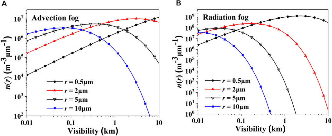
FIGURE 1. Distribution of fog particles with different radii versus visibility in fogs. (A) Advection fog. (B) Radiation fog.
3 The scattering of Bessel beams by fog particles
A Bessel beam is a vortex beam whose field distribution can be expressed by the column Bessel function, whose electric field expression is [24]:
here
According to the angular spectrum theory, a Bessel beam can be seen as a coherent superposition of an infinite number of plane beams whose wave vectors are located on the cone and have the same angle between them and the z-axis, which is called the semi-conical angle of the Bessel beam [25–27].
The Bessel beam can be expressed as a superposition of plane beams
where
For Bessel beams polarized along the x-axis and polarized along the y-axis, the polarization direction vector
Firstly, the plane beams are expressed by the spherical vector wave function series [28],
where
For a Bessel beam polarized along the x-axis, the x-direction polarization vector (6) is Substituted into (9),
For a Bessel beam polarized along the y-axis, the y-direction polarization vector (7) is Substituted into (9),
Substituting the expansion equation of the plane beams (8) into formula (5) of the Bessel vortex beam, the integral of the azimuth angle
here
Finally, the expansion of the spherical vector wave function of the vector Bessel beam is obtained
Its expansion coefficient
For a Bessel beam polarized along the x-axis
And a Bessel beam polarized along the y-axis
According to the relationship between the electric field and the magnetic field
To solve the spherical scattering field of the beam, the scattering field
By applying the electromagnetic field boundary conditions to each part of the electromagnetic field, the scattering coefficient
According to the results of the scattering coefficient of the Bessel beam, the expression of the scattering field can be further obtained. Substituting the scattering field coefficient and the spherical vector wave function into the expression of the scattering field, considering the far-field approximation of the Hankel function, the far field scattering can be represented by two transverse components
The expression of the scattering amplitude function is as follows
where
Figure 2 shows the curves of the differential scattering cross-section (DSCS) of fog particles as a function of the angle when incident with a Bessel beam at different half-conic angles. As can be seen from Figure 2, the change of the half-conic angle of the Bessel beam has a great influence on the micro-dispersed cross-section of the particles. In most scattering angle directions, the micro-dispersed cross-section decreases with the increase of the half-conic angle.
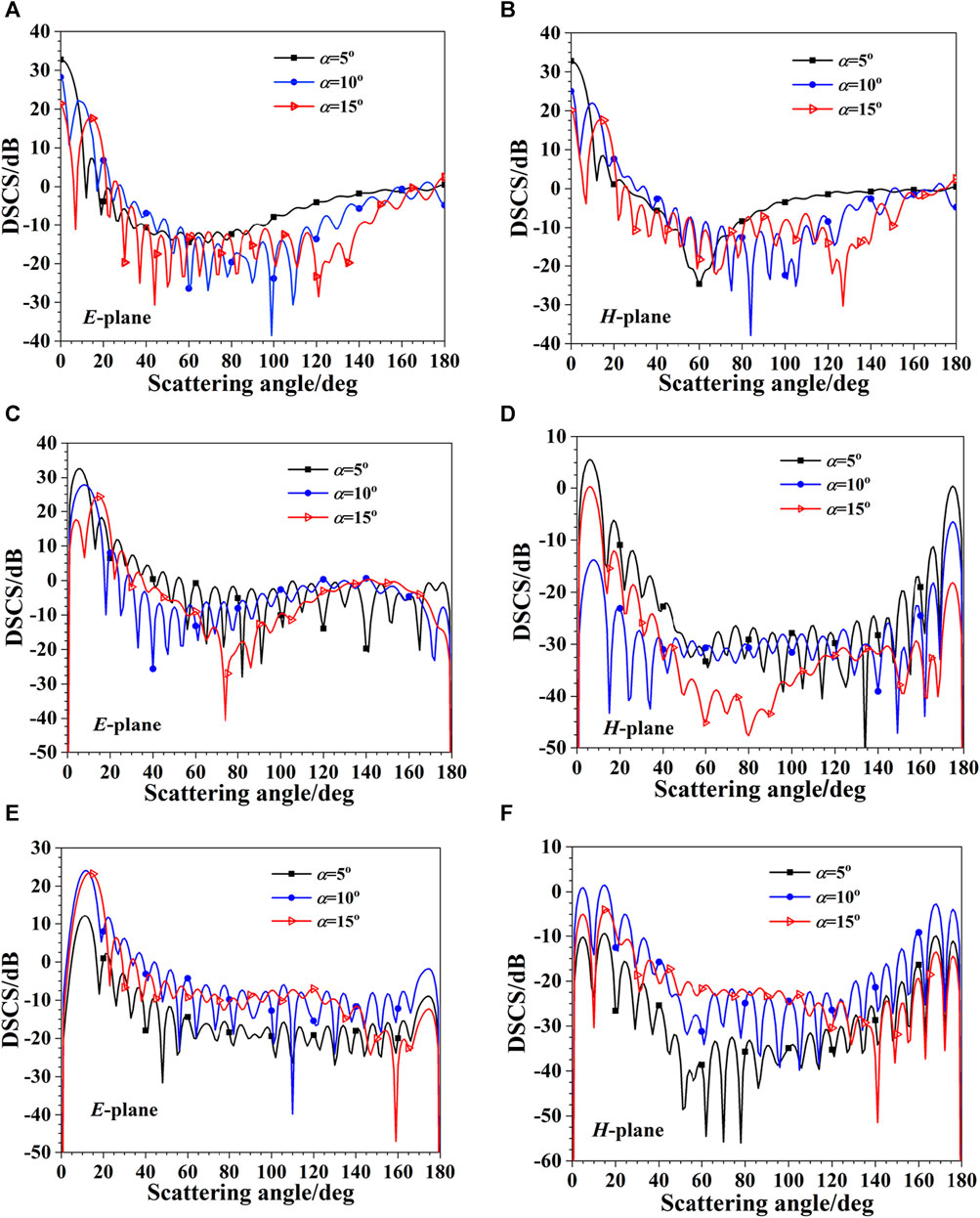
FIGURE 2. Differential scattering cross-section (DSCS) of Bessel beams. (A) l = 0, E-plane; (B) l = 0, H-plane; (C) l = 1, E-plane; (D) l = 1, H-plane; (E) l = 3, E-plane; (F) l = 3, H-plane.
Many researchers expressed a Bessel beam as superposition of plane beams [25–27], used diffraction theories to explain the Bessel self-healing mechanism. In our paper, similar with these researchers, a Bessel beam is also considered as a set of plane beams propagating on a cone, as shown in Figure 3.

FIGURE 3. (A) A plane beam irradiates a water particle of fog. (B) A Bessel beam irradiates a water particle of fog.
The obstacle is a spherical water particle on z-axis, the average intensity of the plane beams irradiating on the water particle is same as that of the Bessel beam, then, by using the scattering theories, we calculate the DSCS of a water particle with a plane beam (PB) and a Bessel beam (BB) irradiating respectively, as shown in Figure 4, comparing with a plane beams, Bessel beams have less DSCS at most scattering angles. That mean, the water particle on z-axis has less effect on the superposition of plane beams propagating on a cone, comparing with the effect on a plane beam propagating along z-axis. The Bessel beam can reconstruct behind the water particle. The scattering theories in our paper and the diffraction theories in the literature [25–27] are descriptions of self-healing mechanism of Bessel beams in different way.
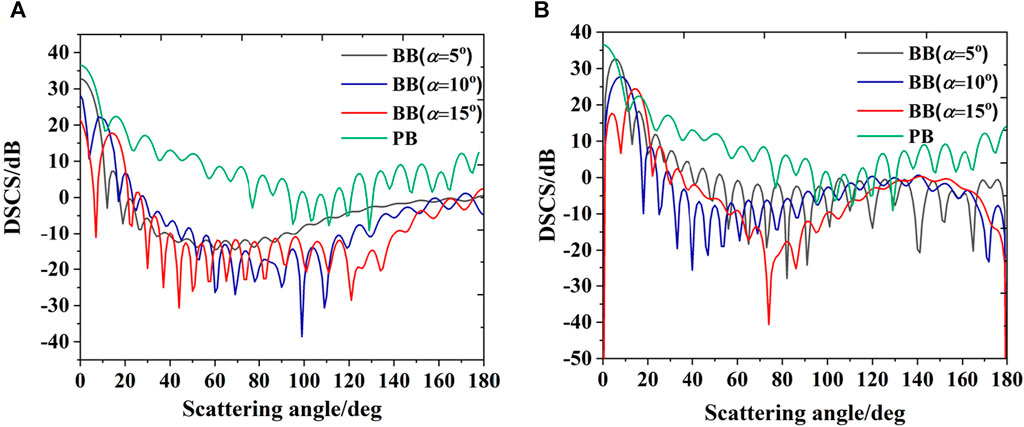
FIGURE 4. (A) DSCS (E-plane) for plane beam (PB) and Bessel beams (BB), for Bessel beams, l = 0,α = 5o, 10 o, 15 o respectively. (B) DSCS (E-plane) for plane wave beam (PB) and Bessel beams (BB), for Bessel beams, l = 1,α = 5o, 10 o, 15 o respectively.
4 Multiple scattering theory for Bessel beams prorogation in fogs
In 2013, Shen [29] focused on the attenuation of 0.532 μm wavelength laser in fog based on the Mie theory, and established an attenuation model. In 2019, Ma [30] used the Mie theory and Monte Carlo method to study the scattering and radiative transfer characteristics of a dense optical soft particle system, and found that particle agglomeration has a significant impact on the scattering characteristics of particles, and the scattering coefficient and asymmetry factor of particles increase significantly with the increase of agglomeration. In the same year, Wang [31] extended the theoretical framework of forward and backward Monte Carlo radiative transfer modeling based on the newly derived forward and backward vector scattering radiative transfer equations. In 2020, Zhang [32] proposed an improved Monte Carlo simulation to track the scattering of radiation in a multi-disperse sea fog layer, which can more accurately calculate the reflection and transmission of radiation through the propagation of sea fog with two different refractive indices, and compare it with previous results.
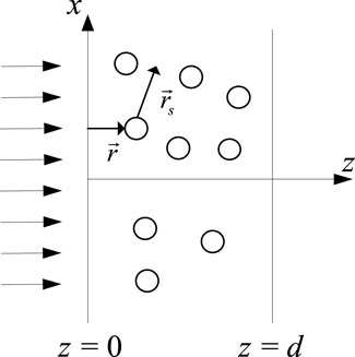
As shown in Figure 5, the incident plane is the xz plane, and z = 0 and z = h are the boundaries of the medium. The incident plane of the medium is z = 0, and the interface is z = h, without considering boundary reflection.
Assuming that the medium is passive and there is no interaction between the particles, the reduction intensity rate
The diffusion strength rate
Intensity rate
The average attenuation cross section
By definition, the albedo of the average particle satisfies
The average phase function of the particle swarm is
where
The scattering angle cosine satisfies
Since the phase function is only affected by angles
integral
Substituting (32) into the above Eq. 33 yields
where
here
The reduction intensity rate
Integrating Eq. 37 yields
The corresponding boundary conditions are
Equation 38 describes the multiple scattering of electromagnetic waves in a random medium.
5 Simulations of Bessel beams propagation in fogs
A Bessel beam is a non-diffraction beam. We set the direction of the photon exit perpendicular to the incident interface, as shown in Figure 6.
The Bessel beams propagation in the fog are calculated by Monte Carlo method, The Bessel beam is sampled by 106 photons, and the light intensity distribution is expressed by the number of photons. The number of photons sampled meets the Bessel function distribution. and the energy weight of each photon is equal to 1. From the previous theoretical section, the average extinction cross-sections of fog droplets corresponding to different visibility were calculated in Table 1, these were used for photon transfer calculation by Monte Carlo method. The incident wavelength is 1.55μm, and the corresponding complex refractive index of the fog particles is 1.318 + i9.86 × 10−5. The imaginary part of the complex refractive index is very small, indicating that the absorption of fog particles is very weak, so
Then, the attenuation and scattering of Bessel beam in fog is analyzed by simulating the transmitted light intensity distribution after a certain distance of transmission in advection fog and radiant fog with different visibility.
Figure 7 shows the intensity distribution of the a first-order Bessel beam with a wavelength of 1.55 μm and a half-cone angle of
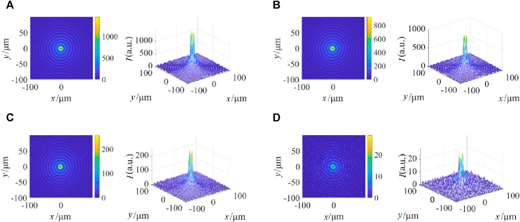
FIGURE 7. Intensity distribution of Bessel beam in advection fog for different visibility. (A) V = 0.3 km. (B) V = 0.2 km. (C) V = 0.1 km. (D) V = 0.05 km.
Figure 8 calculates the intensity distribution of a first-order Bessel beam with a wavelength of 1.55 μm and a half-cone angle of the transmitted light transmitting 1 km in the radiation fog of different visibility. As shown in the figure, the attenuation of the Bessel beam by the radiation fog becomes stronger as visibility decreases. Comparing Figure 7 with Figure 8, it can be intuitively seen that under the same visibility, the attenuation of the Bessel beam by the radiation fog is stronger, especially when the visibility V = 0.05 km, the Bessel beam is almost completely scattered after 1 km of transmission in the radiation fog.
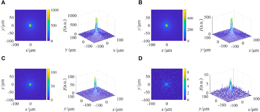
FIGURE 8. Intensity distribution of Bessel beam in radiation fog for different visibility. (A) V = 0.3 km. (B) V = 0.2 km. (C) V = 0.1 km. (D) V = 0.05 km.
Figure 7 and Figure 8 show that when the visibilities are relatively high (V = 0.3km, 0.2 km), the Bessel beam can maintain the original optical field structure well. As the visibilities are very low (V = 0.1km, 0.05 km), the optical field structure is destroyed, resulting in irregular optical field fluctuations. However, the central main lobe can still maintain high intensity, and the surrounding ring can still be distinguished, demonstrating the strong self-healing ability of the Bessel beam.
Figure 9 shows the intensity distribution of transmitted light at different distances H from a first-order Bessel beam with a wavelength of 1.55 μm and a half-conic angle of 1.55 μm in advection fog with visibility V = 0.05 km. As can be seen from the figure, the farther the Bessel beam travels in the fog, the stronger the attenuation effect of the fog on the Bessel beam.

FIGURE 9. Intensity of Bessel beams at different distances in the advection fog (V = 0.05 km). (A) H = 0.3 km. (B) H = 0.5 km. (C) H = 0.7 km. (D) H = 1.0 km.
Figure 10 shows the transmitted light intensity distribution of a first-order Bessel beam with a wavelength of 1.55 μm and a half-cone angle of
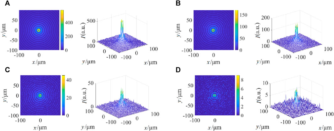
FIGURE 10. Intensity of Bessel beams at different distances in the radiation fog (V = 0.05 km). (A) H = 0.3 km. (B) H = 0.5 km. (C) H = 0.7 km. (D) H = 1.0 km.
From Figure 9 and Figure 10, it can be seen for the low visibility, as the transmission distance increases, the Bessel beam optical field structure gradually breaks down, but its central main lobe and surrounding ring can still be distinguished, showing the strong self-reconstruction ability of Bessel beams.
Figure 11 shows the transmissivity and reflectivity of Bessel beam propagation in advection fog at a wavelength of 1.55 μm with a half-conic angle of
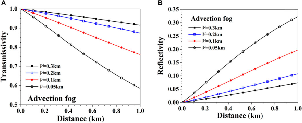
FIGURE 11. Transmissivity and reflectivity of Bessel beam in advection fog with different visibilities. (A) Transmissivity. (B) Reflectivity.
Figure 12 shows the transmissivity and reflectivity of a first-order Bessel beam with a wavelength of 1.55 μm and a semi-conic angle of
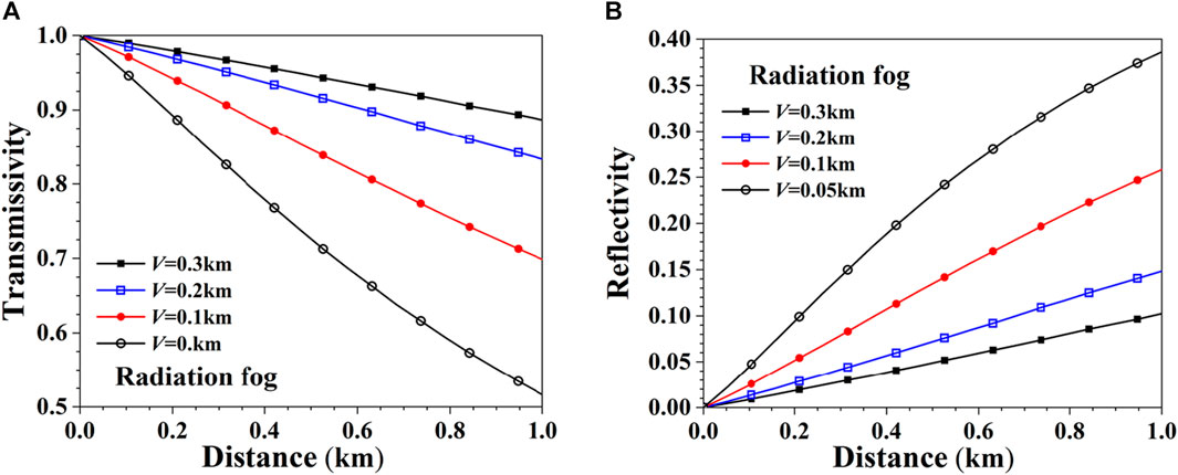
FIGURE 12. Transmissivity and reflectivity of Bessel beams in radiation fog with different visibilities. (A) Transmissivity. (B) Reflectivity.
Figure 13 shows the transmissivity and reflectivity of Bessel beams of different orders with a wavelength of 1.55 μm and a half-cone angle of
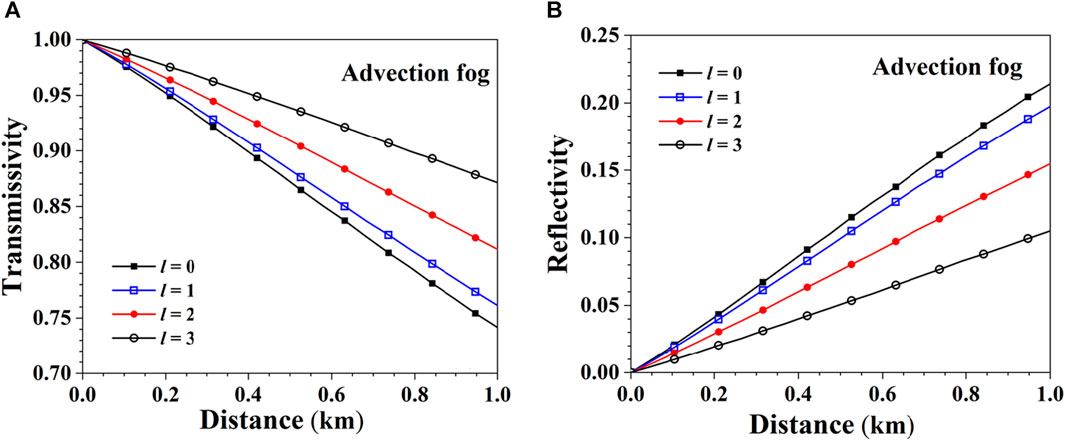
FIGURE 13. Transmissivity and reflectivity of different orders Bessel beams in advection fog. (A) Transmissivity. (B) Reflectivity.
Figure 14 shows the transmissivity and reflectivity curves of Bessel beams of different orders with a wavelength of 1.55 μm and a semi-conic angle of
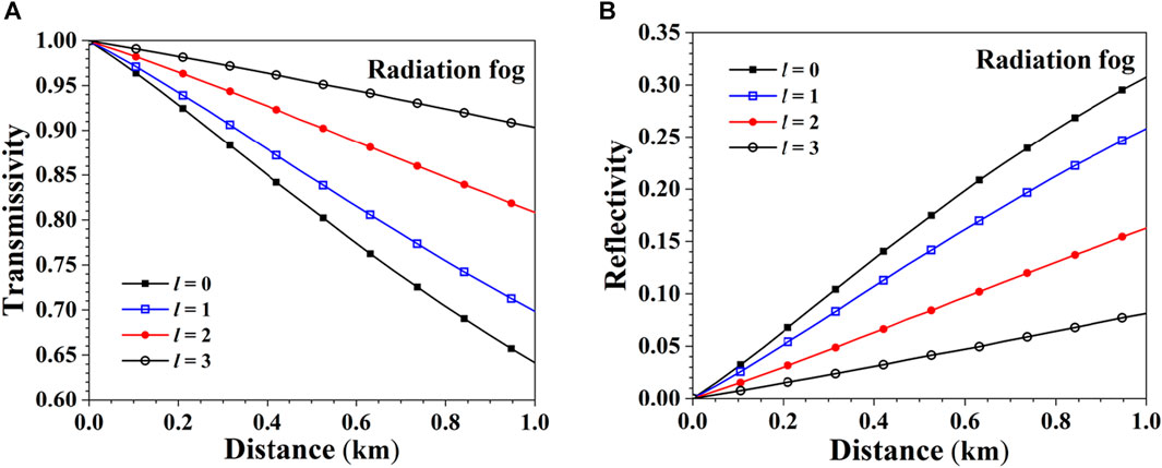
FIGURE 14. Transmissivity and reflectivity of different orders Bessel beams in radiation fog. (A) Transmissivity. (B) Reflectivity.
In order to compare the transmission performance of the two beams in fog, the reflectivity of the Bessel beam and the plane beams is compared, and the ability of the two beams to penetrate the fog is analyzed. In order to facilitate comparison, one wavelength of the visible (0.63 μm), the near-infrared (1.55 μm) and the mid-infrared (10.6 μm) were selected for comparative analysis.
Figure 15 shows the transmissivity and reflectivity of a first-order Bessel beam with a plane beams in advection fog with a visibility of 0.1 km. As can be seen from the figure, the transmissivity of the Bessel beam in advection fog is greater than that of the plane beams at the same wavelength, and the reflectivity is lower than that of the plane beams, these are because the strong self-healing and non-diffraction character of Bessel beams in fogs. From the definition of the complex refractive index, the imaginary part of the complex refractive index corresponds to the absorption capacity of light. From Table 2, it can be seen that the imaginary part of the complex refractive index of visible (wavelength is 0.63 μm) and near-infrared (wavelength is1.55 μm) light is very small, indicating that the absorption of fog particles is very weak, while the imaginary part of the complex refractive index of the mid-infrared light (wavelength is 10.6 μm) is larger, resulting in stronger absorption and attenuation as shown in Figure 15.
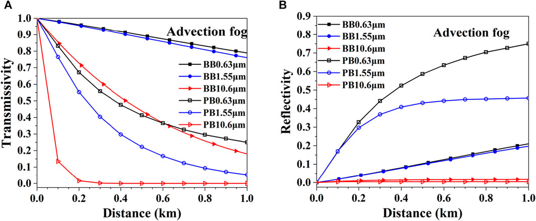
FIGURE 15. Comparison of Bessel beams (BB) and plane beams (PB) in advection fog. (A) Transmissivity. (B) Reflectivity.
Figure 16 shows the transmissivity and reflectivity of a first-order Bessel beam with a plane beams in a radiation fog with a visibility of 0.1 km. The transmissivity of Bessel beams of the same wavelength in the radiation fog is greater than that of plane beams. It can be observed in the figure that the transmissivity of plane beams in radiation fog is different from that in advection fog, mainly when the wavelength of 10.6 μm is transmitted in radiation fog, the scattering effect of fog particles on this wavelength is mainly Rayleigh scattering, so that the transmissivity of plane beams at this wavelength is very close to that of Bessel beams. It can be concluded that in most cases, compare with plane beams, because of self-healing and non-diffraction, Bessel beams can propagate longer distance in fogs.
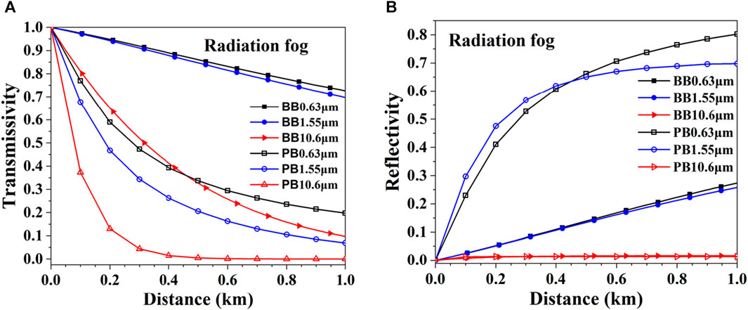
FIGURE 16. Comparison of Bessel beams (BB) and plane beams (PB) in radiation fog. (A) Transmissivity. (B) Reflectivity.
6 Conclusion
Based on the calculation of the scattering characteristics of a single fog particle by the Bessel beam, the Monte Carlo model of the transmission of Bessel beams in fog is established. The transmissivity of the Bessel beam in fog with different visibility is calculated, and the intensity distribution of transmitted light at different distances in fog with different visibility is gotten. It can be found that when the visibility is the same, the attenuation effect of radiation fog on the Bessel beam is stronger than that in advection fog. The influences of Bessel beam parameters (topological charge, semi-conic angle and wavelength) on the transmissivity were studied. The analysis shows that the larger the topological charge number, the larger the semi-conic angle, and the greater the transmissivity of the Bessel beam. the transmissivity of the visible band (0.63 μm) and the near-infrared band (1.55 μm) is similar, while the Bessel beam in the mid-infrared band (10.6 μm) has a strong absorption attenuation effect on the wavelength and low transmissivity due to the larger imaginary part of the complex refractive index at this wavelength. Finally, the propagation characteristics of the Bessel beam in the fog are compared with the plane beams, and the simulation results show the self-healing ability of the Bessel beams propagation in the fogs, and comparing with the plane beams, the longer propagation distance of Bessel beams in the fogs.
Data availability statement
The raw data supporting the conclusions of this article will be made available by the authors, without undue reservation.
Author contributions
CR: Data curation, Software, Writing–original draft. ZY: Software, Writing–original draft. XQ: Conceptualization, Writing–review and editing. HY: Writing–review and editing. ZW: Writing–review and editing.
Funding
The author(s) declare financial support was received for the research, authorship, and/or publication of this article. This work was supported by the National Natural Science Foundation of China (Grant no. 61975158) and Aeronautical Science Foundation (Grant no.2023M073081004).
Conflict of interest
The authors declare that the research was conducted in the absence of any commercial or financial relationships that could be construed as a potential conflict of interest.
The handling editor MC declared a shared affiliation with the author(s) at the time of review.
Publisher’s note
All claims expressed in this article are solely those of the authors and do not necessarily represent those of their affiliated organizations, or those of the publisher, the editors and the reviewers. Any product that may be evaluated in this article, or claim that may be made by its manufacturer, is not guaranteed or endorsed by the publisher.
References
1. Durnin J. Exact solutions for nondiffracting beams. I. The scalar theory. J.opt.soc (1987) 4:651–4. doi:10.1364/josaa.4.000651
2. Gori F, Guattari G, Padovani C. Bessel-gauss beams. Opt Commun (1987) 64(6):491–5. doi:10.1016/0030-4018(87)90276-8
3. Mishra SR. A vector wave analysis of a bessel beam. Opt Commun (1991) 85(2-3):159–61. doi:10.1016/0030-4018(91)90386-r
4. Volkesepulveda K, Arlt J, Dholakia K, Dholakia K. Orbital angular momentum of a high-order bessel light beam. J Opt B Quan Semiclassical Opt (2002) 4(2):S82–9. doi:10.1088/1464-4266/4/2/373
5. Mitri FG. Vector wave analysis of an electromagnetic high-order bessel vortex beam of fractional type α. Opt Lett (2011) 36(5):606–8. doi:10.1364/ol.36.000606
6. Gouesbet G, Lock JA. A darkness theorem for the beam shape coefficients and its relationship to higher-order non-vortex bessel beams. J Quantitative Spectrosc Radiative Transfer (2017) 201:229–35. doi:10.1016/j.jqsrt.2017.07.023
7. Fuscaldo W, Burghignoli P, Galli A. A comparative analysis of bessel and Gaussian beams beyond the paraxial approximation. Optik - Int J Light Electron Opt (2021) 240(10):166834. doi:10.1016/j.ijleo.2021.166834
8. Marston PL. Scattering of a bessel beam by a sphere. J Acoust Soc America (2007) 121(2):753–8. doi:10.1121/1.2404931
9. Taylor JM, Love GD. Multipole expansion of bessel and Gaussian beams for mie scattering calculations. J Opt Soc America A (2009) 26(2):278–82. doi:10.1364/josaa.26.000278
10. Mitri FG. Arbitrary scattering of an electromagnetic zero-order bessel beam by a dielectric sphere. Opt Lett (2011) 36(5):766–8. doi:10.1364/ol.36.000766
11. Shoorian H, Sounas D, Caloz C. Bessel beam scattering by a conducting sphere. In: Proceedings of the 2012 IEEE International Symposium on Antennas and Propagation; July, 2012; Chicago, IL, USA (2012).
12. Valdivia N, Votto L, Gouesbet G, Wang J, Ambrosio LA. Bessel-gauss beams in the generalized lorenz-mie theory using three remodeling techniques. J Quantitative Spectrosc Radiative Transfer (2020) 256(2):107292. doi:10.1016/j.jqsrt.2020.107292
13. Kreid DK. Atmospheric visibility measurement by a modulated cw lidar. Appl Opt (1976) 15(7):1823. doi:10.1364/ao.15.001823
14. Vasseur H, Gibbins CJ. Inference of fog characteristics from attenuation measurements at millimeter and optical wavelengths. Radio Sci (1996) 31(5):1089–97. doi:10.1029/96rs01725
15. Eloranta EW. Practical model for the calculation of multiply scattered lidar returns. Appl Opt (1998) 37(12):2464–72. doi:10.1364/ao.37.002464
16. Hess M, Koepke P, Schult I. Optical properties of aerosols and clouds: the software package opac. Bull Am Meteorol Soc (1998) 79(5):831–44. doi:10.1175/1520-0477(1998)079<0831:opoaac>2.0.co;2
17. Shen Y, Pidishety S, Nape I, Dudley A. Self-healing of structured light: a review. J Opt (2022) 24:103001. doi:10.1088/2040-8986/ac8888
18. Vetter C, Steinkopf R, Bergner K, Ornigotti M, Nolte S, Gross H, et al. Realization of free-space long-distance self-healing bessel beams. Laser Photon Rev (2019) 13(10):1900103. doi:10.1002/lpor.201900103
19. Anguiano-Morales M. Self-healing properties of asymmetric Bessel beams. Opt Quan Elect (2018) 50:363. doi:10.1007/s11082-018-1636-4
20. Fahrbach F, Rohrbach A. Propagation stability of self-reconstructing Bessel beams enables contrast-enhanced imaging in thick media. Nat Commun (2012) 3:632. doi:10.1038/ncomms1646
21. Zeng X, Chu J, Cao W, Kang W, Zhang R. Visible-IR transmission enhancement through fog using circularly polarized light. Appl Opt (2018) 57(23):6817–22. doi:10.1364/ao.57.006817
22. Zhang C, Zhang J, Wu X, Huang M. Numerical analysis of light reflection and transmission in poly-disperse sea fog. Opt Express (2020) 28(17):25410–30. doi:10.1364/oe.400002
23. Zhao Z, Wu Z. Millimeter-wave attenuation due to fog and clouds. Int J Infrared Millimeter Waves (2000) 21(10):1607–15. doi:10.1023/A:1006611609450
24. Dartora CA, Nobrega KZ. Study of Gaussian and Bessel beam propagation using a new analytic approach. Opt Commun (2012) 285(5):510–6. doi:10.1016/j.optcom.2011.11.015
25. Aiello A, Agarwal GS. Wave-optics description of self-healing mechanism in Bessel beams. Opt Lett (2014) 39(24):6819–22. doi:10.1364/ol.39.006819
26. Aiello A, Agarwal G, Paúr M, Stoklasa B, Hradil Z, Řeháček J, et al. Unraveling beam self-healing. Opt Express (2017) 25:19147–57. doi:10.1364/oe.25.019147
27. McGloin D, Dholakia K. Bessel beams: diffraction in a new light. Contemp Phys (2005) 46(1):15–28. doi:10.1080/0010751042000275259
28. Ma X, Li E. Scattering of an unpolarized bessel beam by spheres. Chin Opt Lett (2010) 8(12):1195–8. doi:10.3788/col20100812.1195
29. Shen N, Zhang XJ, Guo J. Attenuation of laser fuse through fog. Opt Precision Eng (2013) 21(4):864–9. doi:10.3788/OPE.20132104.0864
30. Ma LX, Xie BW, Wang CC, Liu L. Radiative transfer in dispersed media: considering the effect of host medium absorption on particle scattering. J Quantitative Spectrosc Radiative Transfer (2019) 230:24–35. doi:10.1016/j.jqsrt.2019.03.021
31. Wang Z, Cui SC, Zhang ZB, Yang J, Gao H, Zhang F. Theoretical extension of universal forward and backward Monte Carlo radiative transfer modeling for passive and active polarization observation simulations. J Quantitative Spectrosc Radiative Transfer (2019) 235:81–94. doi:10.1016/j.jqsrt.2019.06.025
Keywords: Bessel beam, scattering, propagation, advection fog, radiation fog
Citation: Chen R, Zhang Y, Xu Q, Han Y and Wu Z (2024) Multiple scattering of Bessel beams propagating in advection fog and radiation fog. Front. Phys. 12:1356528. doi: 10.3389/fphy.2024.1356528
Received: 15 December 2023; Accepted: 12 February 2024;
Published: 28 February 2024.
Edited by:
Mingjian Cheng, Xidian University, ChinaReviewed by:
Alfonso Padilla-Vivanco, Universidad Politécnica de Tulancingo, MexicoYijie Shen, Nanyang Technological University, Singapore
Copyright © 2024 Chen, Zhang, Xu, Han and Wu. This is an open-access article distributed under the terms of the Creative Commons Attribution License (CC BY). The use, distribution or reproduction in other forums is permitted, provided the original author(s) and the copyright owner(s) are credited and that the original publication in this journal is cited, in accordance with accepted academic practice. No use, distribution or reproduction is permitted which does not comply with these terms.
*Correspondence: Qiang Xu, cXh1QHhpZGlhbi5lZHUuY24=
 Run Chen
 Qiang Xu
 Yiping Han