
94% of researchers rate our articles as excellent or good
Learn more about the work of our research integrity team to safeguard the quality of each article we publish.
Find out more
ORIGINAL RESEARCH article
Front. Phys., 16 November 2023
Sec. Medical Physics and Imaging
Volume 11 - 2023 | https://doi.org/10.3389/fphy.2023.1269495
This article is part of the Research TopicMultidisciplinary Approaches to The FLASH RadiotherapyView all 12 articles
 Jake Harold Pensavalle1,2,3
 Francesco Romano4,5*
 Mariagrazia Celentano1,3
 Damiano Del Sarto1,3
 Giuseppe Felici2
 Gaia Franciosini6Luigi Masturzo1,2,3
 Giuliana Milluzzo4
 Vincenzo Patera6
 Yolanda Prezado7
 Fabio Di Martino1,3,8,9
The use of the flash effect and mini-beams have demonstrated the ability to spare healthy tissue while maintaining the same effectiveness in controlling tumors. In this study, we present the implementation and comprehensive dosimetric characterization of low-energy mini-beam radiation therapy at both conventional and ultra-high dose rates. These beams possess important features that allow for a wide range of spatial and temporal parameter variations, independently or simultaneously, for both effects. This novel capability enables the performance of in vivo/vitro radiobiological experiments, which are crucial for understanding the underlying mechanisms and quantitative dependencies of these effects on their respective parameters. This understanding is essential for evaluating the potential clinical applications of the two effects both individually and in terms of their potential synergistic actions.
The initial intuition that led to the development of spatially fractionated radiotherapy (SFRT) was credited to Dr. Alban Köhler in 1909. Köhler discovered that by introducing a grid-shaped shielding system for X-ray beams (at that time, X-ray tubes were the only radiation source), he was able to treat skin tumors more effectively while significantly reducing damage to healthy tissue. Erythema and necrosis healed within a few weeks, leaving the new epidermal tissue completely healthy [1]. Although this approach was initially used for the treatment of some superficial tumors, it remained on the sidelines of radiotherapy development for a long time. However, since the 1990s, several research groups in Europe and the United States have begun to consider the possibility of implementing spatial fractionation in radiotherapy. Multiple radiobiology studies were conducted, initially using X-rays, including synchrotron light [2–5] and later with proton beams [2, 3, 6–10]. These studies have demonstrated that this highly unconventional approach has the potential to be revolutionary, allowing significant sparing of healthy tissue while maintaining local tumor control. This outcome presents evident clinical prospects once radiation therapy accelerators (medical devices) capable of delivering such treatment become available. Most SFRT techniques spare normal tissues with conventional dose rates [11, 12]. Experiments combining Ultra High Dose Rates (UHDR) with SFRT using Microbeam Radiotherapy (MRT) and mini-beam Radiotherapy (MBRT) have been conducted [13, 14], however, establishing the additive or synergistic effects of combining these techniques is still pending, and separating the flash effect from spatial fractionation in MRT studies has yielded inconclusive results [15].
Conventional radiotherapy has always followed the paradigm of using a uniform beam to deliver the same dose to the target. In contrast, SFRT proposes the possibility of achieving a spatially periodic structure where the transverse profile is articulated in a recurring series of “peaks and valleys” [3]. The optimal structure of this pattern, which refers to the peak-to-valley dose ratio (PVDR) and the spatial extent of the “light and shadow” regions, is still the subject of ongoing research. SFRT can be implemented in two different modes, irrespective of the radiation source employed. The first mode involves using a spatially homogeneous beam and positioning a periodic screen with alternating slits and solid elements, known as the GRID technique [16–19], between the source and the target. This approach, initially proposed by Köhler in 1909 and replicated in experiments using synchrotron light with microbeams, has demonstrated promising results. The second mode utilizes the pencil beam technique, wherein multiple narrow beams, referred to as “pencil beams,” are employed to paint the desired dose distribution pattern. This requires charged particles. Proton accelerators have been particularly suitable for implementing this approach, even though most radiobiological studies have used passive collimation [20–25].
While GRID therapy has found clinical success in palliative applications and mini beam RT is approaching clinical trials with enormous potential, SFRT has not gained widespread adoption not only due to technological limitations of current available devices, as detailed in [21], but also due to the high heterogeneity of tumor coverage, which is in stark contrast to conventional radiotherapy.
Furthermore, it is important to emphasize that the optimal use of SFRT with low energy electron beams is limited to the context of potential flash delivery, as extensively discussed in [2]. Therefore, the study of the combined flash and mini-beam effect is a key aspect, and this present work serves as a foundation for future research.
A dedicated beam with the ability to independently adjust its parameters is essential not only for advancing radiobiology research but also for facilitating accurate dosimetric studies, as was the case of flash [26]. This capability has been demonstrated to be valuable in previous research involving electron Ultra High Dose per Pulse (UHDP) beams, where fundamental dosimetry solutions have been developed [27–30].
In fact, for low energy electrons an immediate application in the clinic would be Intra Operative Radiotherapy (IORT). However, the study of the mini-beam effect is fundamental in the perspective of Very High Energy Electron (VHEE) irradiation, since the mini-beam effect may play a major role since VHEE will most likely be delivered via pencil beams, that allow the possibility of “painting” the spatial dose distribution [18].
In this paper, we explore the potential of using electron mini-beams in conjunction with flash irradiation. The flash effect, as described in previous studies [31–33], is observed when irradiation times are shorter than 0.1–0.2 s, and the average dose rate exceeds 40–100 Gy/s. The mini-Beam distribution, correlated to a tissue sparing effect [3], is characterized by a spatial dose distribution with alternating peaks and valleys, where the full width at half maximum (FWHM) of the peaks is less than 1 mm, and the distance between successive peaks is 2–4 times the FWHM. Although the combination of these two techniques has not been experimentally evaluated yet, it has the potential for a synergistic action, resulting in a significant reduction in the side effects of radiation therapy while maintaining therapeutic efficacy. Therefore, we can deliver irradiation in four different modalities (Conventional, flash, mini-Beam, and mini-beam-flash), independently varying their main parameters, to study the individual and combined effects of these techniques.
To explore the possibility of creating UHDR mini beams, Monte Carlo simulations were carried out reproducing different devised suitable collimator templates, which are passive spatial distribution modulators. These templates are integrated into the beam optic system to achieve mini-beam spatial distributions.
The mini-beam templates have been designed with the GEANT4 [34] version 10.7.2 Monte Carlo code. In particular, the Sordina IORT Technologies S.p.A. (SIT, Italy) ElectronFlash linear accelerator (linac) available at the Centro Pisano for Flash Radiotherapy (CPFR) was fully modelled, in terms of beam optics, geometry and input energy spectra with the Geant4 code, and a dedicated application was recently inserted within the official advanced examples of the Geant4 distribution with the name “eFLASH_radiotherapy.” For each simulation, the GEANT4 standard_opt4 physics list with 108 primary particles and 0.1 mm production cuts were set. A water phantom was implemented just after the template to score the dose, using a 0.125 × 0.125 × 0.5 mm3 voxel size.
A fundamental requisite for a useful mini-beam structure, defined as having distinct peaks and valleys with high peak-to-valley dose ratio, is avoiding bleed-through of electrons through the septa, thus high Z materials are needed. In fact, by keeping the thickness equal to the practical range of the electron energy (9 MeV nominal energy), we noticed a significant reduction of PVDR for plastic materials, such as Teflon, as opposed to Tungsten due to septa bleed-through, as shown in Figure 1. Similar results have been reported also in [35] in the context of experimental IORT beam limiting devices.
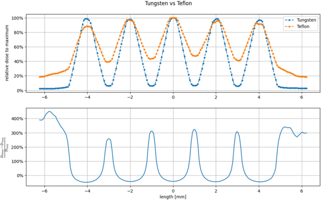
FIGURE 1. Comparison between Tungsten (thickness 5 mm) and Teflon (thickness 25 mm) grid-hole template superficial dose profiles. The thickness has been calculated as the practical range extrapolated from the PDD in the selected material. We can see that Teflon cannot achieve useful peak to valley ratio since the thickness of the walls of the holes (1 mm) are much smaller than the practical range.
Thus, we designed the collimators to have a thickness of 5 mm and be made of Tungsten. Each of the designed templates differs mainly in hole structure (grid or planar slits) and center-to-center distance (ctc), so that it is possible to study the effect of varying these parameters.
To further strengthen the reliability of dose evaluations in terms of spatial distribution, we compared the Monte Carlo simulations with experimental data acquired with radiochromic gafchromic films, which are currently considered the most suitable dosimeters with high spatial resolution (below 25 µm [36]). However, it is important to acknowledge that these dosimeters have certain limitations, mostly related to the accuracy of dose reading [37]. To address this, we conducted a comparative analysis by comparing the gafchromic data with results obtained from three independent Monte Carlo simulation codes: Electron Gamma Shower by the National Research Council Canada (EGSnrc) [38], Geant4, and FLUKA [39, 40]. The realistic input energy spectrum and spatial distribution before the Titanium window were provided by SIT Sordina company. To validate the accuracy of the simulations, we compared them with measurements obtained using the FlashDiamond [41] detector, including PDD and dose profile measurements. In order to obtain absolute dose values from the simulations, we normalized the mini-beam dose percentage with respect to an open field measurement at the buildup region. This normalization was then scaled to the desired depth using the PDD curve.
The simulations performed using EGSnrc consisted of two parts, using the beamline simulation code (BEAMnrc) and the dose deposition simulation code (DOSXYZnrc). At first, a phase space was obtained using BEAMnrc, then the dose was calculated using DOSXYZnrc in the water phantom. The voxel size was adjusted to closely match the dots per inch (DPI) scan setting of the gafchromic film and the film thickness. With BEAMnrc, we modeled the accelerator optics starting from the titanium window down to the tungsten template. To include all the beam optic materials, we expanded the default International Commission on Radiation Units and Measurements (ICRU) material data file (ICRU521) using the EGSnrc graphic interface.
We also recreated the EGSnrc setup using GEANT4 to compare it with the gafchromic measurements. We used the same input spectrum and designed the simulated setup to mimic the modeling approach in EGSnrc. However, in GEANT4, we directly calculated the dose in a water phantom without generating a phase space.
In addition, we replicated the EGSnrc configuration using FLUKA as an alternative comparison to the measurements. Keeping the input spectrum unchanged, the simulated setup closely emulates the modeling methodology employed in EGSnrc. Like in GEANT4, in FLUKA, the dose calculation was performed directly in a water phantom, eliminating the need for generating a phase space.
The flash linac adopted is the Triode-Gun equipped ElectronFlash manufactured by SIT, available at the CPFR in Pisa, Italy. It operates at energies of 7 and 9 MeV, delivering a dose-rate of up to 5,000 Gy/s. Field size and Normal Treatment Distance (NTD) is achieved by means of passive collimation with polymethyl methacrylate (PMMA) cylindrical tubes, called applicators. Each applicator is uniquely identified by its diameter (ex. Applicator 100 mm, 50 mm, 40 mm, etc.). With this linac it’s possible to achieve flash conditions and vary the main parameters (Dose per pulse, pulse width, pulse repletion frequency ecc.) independently from one and another, without changing experimental setup or beam collimation [42].
Measurements were performed using the ElectronFlash linac in 9 MeV mode with a 40 mm diameter applicator. For electron flash, beam monitoring is critical as conventional systems based on ionization chambers are not compatible with the high beam current [43]. As in the case of flash with protons [44], beam monitoring is a topic of great interest which requires non-conventional solution. In fact, ElectronFlash comes equipped with a IEC 60601-2-1 [45] compliant beam current transformer (ACCT) based monitoring system, which correlates the beam current to delivered dose in the form of monitor units (MU) displayed on the machine human interface (HMI) system. After an initial MU calibration check without the mini-beam template, we fixed the pulse width (tp), pulse repetition frequency (PRF), and dose per pulse to ensure each gafchromic film received the same dose at the open field electron beam build up depth (R100). The EBTXD gafchromic films [36] were analyzed with an Epson Expression scanner 10000XL after 48 h, 254 DPI with the background subtracted from a pre-irradiation scan. From the scan, we converted the optical density (OD) to dose with previously measured dose calibration curves. Each film was irradiated accumulating a total dose of 23.5 Gy at R100, using a dose per pulse of about 0.2 Gy/p, tp of 4 µs and a PRF of 50 Hz.
The mini-beam templates were attached to the applicator using a 3D-printed nylon holder, and the films were placed between slabs of a plastic water phantom to measure the dose profile at each depth. The total phantom dimensions are 30 × 30 × 15 cm3, with singular slab thickness ranging from 1 mm to 1 cm. For each template we evaluated the main characteristics, such as ctc, PVDR, irradiated surface, and the effect of hole type and dimensions.
As by design, the nylon holder does not extend beyond the template, ensuring that only the tungsten is in contact with the phantom. For each template, we measured the dose profile at various depths ranging from 0 up to 4 mm water depth, using 25.6 × 25.6 mm2 films positioned perpendicular to the beam axis in the water equivalent phantom. In the case of GRID templates, we sampled additional points along the depth to evaluate the PDD (percentage depth dose). For the PLANAR templates, a 51.2 × 51.2 mm2 film was placed parallel to the beam axis at a depth of 4 mm, with normalization to the entrance dose measured using a 25.6 × 25.6 mm2 film positioned perpendicular to the beam axis during the same irradiation.
Each of the Monte Carlo codes show good agreement with the open field experimental data in the water phantom, as shown in Figure 2. Gamma index analysis [46] was performed for the Monte Carlo curves, comparing each one with the FlashDiamond data. With a Dose Difference (DD) of 3% and a Distance to Agreement (DTA) of 3 mm, we have obtained over a 90% agreement for the curves across all Monte Carlo codes. We decided on these values of DD and DTA due to the dose response and spatial resolution of the FlashDiamond detector [41]. Thus, we can reasonably use the Monte Carlo codes for a comparison with the experimental data.
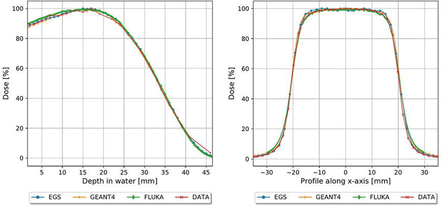
FIGURE 2. Monte carlo simulations plotted with FlashDiamond measurements, PDD (left) and profiles at R100 (right).
The final collimators which have been constructed are shown in Figure 3, which also shows a picture of the template attachment on the PMMA applicator and a close-up of the setup, and in Table 1 the main geometric characteristics of each one is summarized. Each one is 5 × 5 × 0.5 cm3 and is made of Tungsten, to ensure minimal electron septa bleed-through and maintain a useful mini-beam structure. Since the templates are made of a high Z material, it is useful to evaluate secondary radiation and its effect on the mini-beam distribution. As shown in Figure 4, Bremsstrahlung photons, evaluated in the worst-case scenario of the grid_conf2 template (the one with least open volume), constitute less than 10% for depth up to 5 mm of the dose, which is deposited mostly at depths beyond the desired mini-beam structure. A rough approximation can be made by utilizing the radiative stopping powers listed in the National Institute of Standards and Technology (NIST) tables for Tungsten [47]. This calculation overlooks any directional or geometric aspects of the beam and yields an estimate of approximately 10% of the maximum dose attributable to radiative loss.
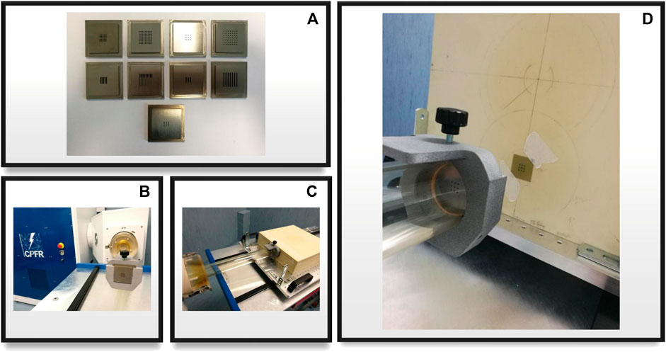
FIGURE 3. (A) All nine template configurations for grid and planar collimators; (B) template mounted on the accelerator’s applicator with a nylon 3d printed holder; (C) experimental setup close-up, applicator, template and phantom are shown; (D) close-up of the beam optics, template and irradiated gafchromic film after dose delivery with a visible mini-beam pattern.
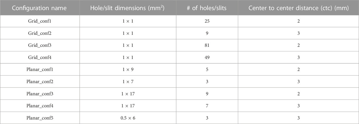
TABLE 1. Mini-beam template geometric parameters.
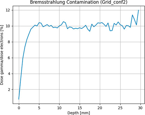
FIGURE 4. Bremsstrahlung photons evaluated as average dose contribution along the depth of a water phantom by separating particles in the phase space after the template.
The templates used for measurement, referenced in Table 1, are as follows:
1. Grid_conf1
2. Grid_conf2
3. Planar_conf1
4. Planar_conf3
In Figures 5, 6, the transversal dose profiles obtained experimentally, at the center of the beam from 0 mm up to 4 mm in water depth are presented for the grid configurations, grid1 and grid2, along with the expected values from the Monte Carlo (MC) simulations. For all profiles, the dose is normalized to the dose at R100 of the open 40 mm field. To evaluate the agreement of the Monte Carlo simulations, we used gamma index analysis with DD of 6% and DTA of 2 mm to achieve an agreement greater than 93% with the experimental data at each depth. The choice of DD and DTA is due to the high dose uncertainty and high spatial resolution of gafchromic films, as pointed out in [36, 37, 41]. The agreement is further observed in the PVDR values reported as function of the depth depicted in Figure 7. As anticipated, a higher ctc results in a significantly greater PVDR, as the increased septa blocks adjacent hole contamination, leading to a substantial decrease in the valley dose at the expense of a lower average dose. Figure 8 illustrates the average dose PDDs (percentage depth dose) and the depth at which PVDR > 2.5 for the grid templates. As comparison, also the equivalent open field (obtained as EGSnrc simulated tungsten slab of 5 mm with an aperture of the dimensions of the hole distribution, in this case 1 cm) is shown. We can observe that a greater ctc considerably expands the “mini-beam zone” (PVDR > 2.5) while creating a steeper PDD. This mini-beam structure covers a zone up to the depth of the 50% dose deposition (R50) in water, while reducing the total penetration of the dose distribution for greater depth. This makes the grid template particularly interesting, as it is possible to obtain a large area of “mini-beam” characteristics, with the possibility of performing in vivo experiments on organs and tissues of dimensions of 5–6 mm. Figures 9, 10 present the profiles for the planar templates, showing a good agreement also above 93% of gamma index with DD 6% and DTA 2 mm. In Figure 11, the PVDR as a function of depth for the planar configuration is displayed. Apart from a slight discrepancy (15%) at the entrance, where a small increase in the valley dose can significantly impact the PVDR, the greater field size does not affect significantly the mini-beam distribution along the depth. Figure 12 shows the PDDs normalized to the entrance dose and “mini-beam zone” (PVDR > 2.5) for the templates, compared to the equivalent open beam configuration (2 × 2 cm2 field). Since the positioning of the film parallel to the beam resulted in an underexposure after the R50 beyond the constructor’s tolerances, that part is omitted on the graph. As expected, with an increase in field size, we approach an open field configuration, resulting in greater penetration, as precedingly reported by [18]. Furthermore, in comparison to the grid configuration, the PDD does not significantly differ from the equivalent open field. This makes the planar template interesting from a clinical point of view, as it has a PDD practically identical to that of the conventional beam of equal energy (same depth of treatment) with the possibility of having a mini-beam effect, for example, on the skin, potentially reducing the collateral effects to this organ.
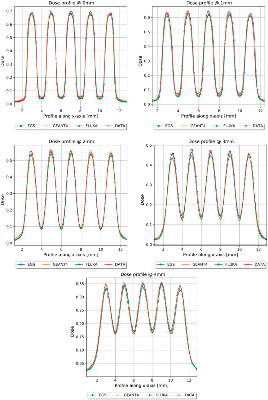
FIGURE 5. Dose profiles, normalized to the dose value of the open field at R100, of the first 4 mm in depth of grid conf1, Monte Carlo vs. Gafchromic film.
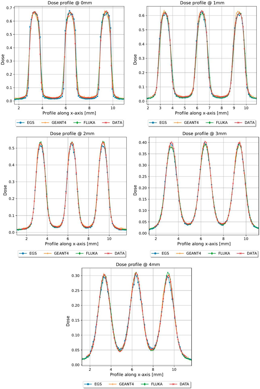
FIGURE 6. Dose profiles, normalized to the dose value of the open field at R100, of the first 4 mm in depth of grid conf2, Monte Carlo vs. Gafchromic film.
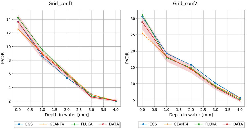
FIGURE 7. PVDR for grid_conf1 (left) and grid_conf2 (right).
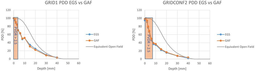
FIGURE 8. PDDs for the grid configurations. For grid_conf1 (left) the “mini-beam zone” extends up to 3 mm, while for grid_conf2 (right) the zone extends to 6 mm.
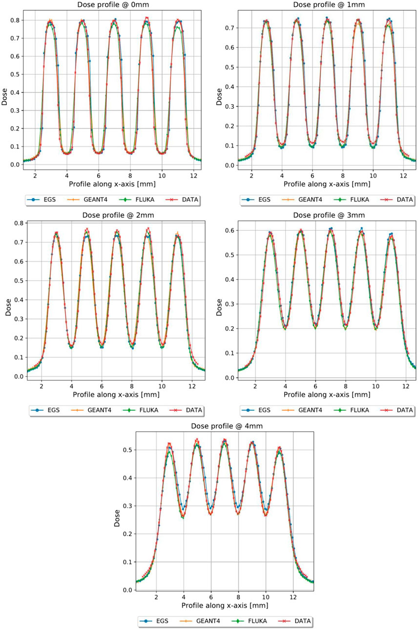
FIGURE 9. Dose profiles, normalized to the dose value of the open field at R100, of the first 4 mm in depth of planar_conf1, MC vs. GAF.
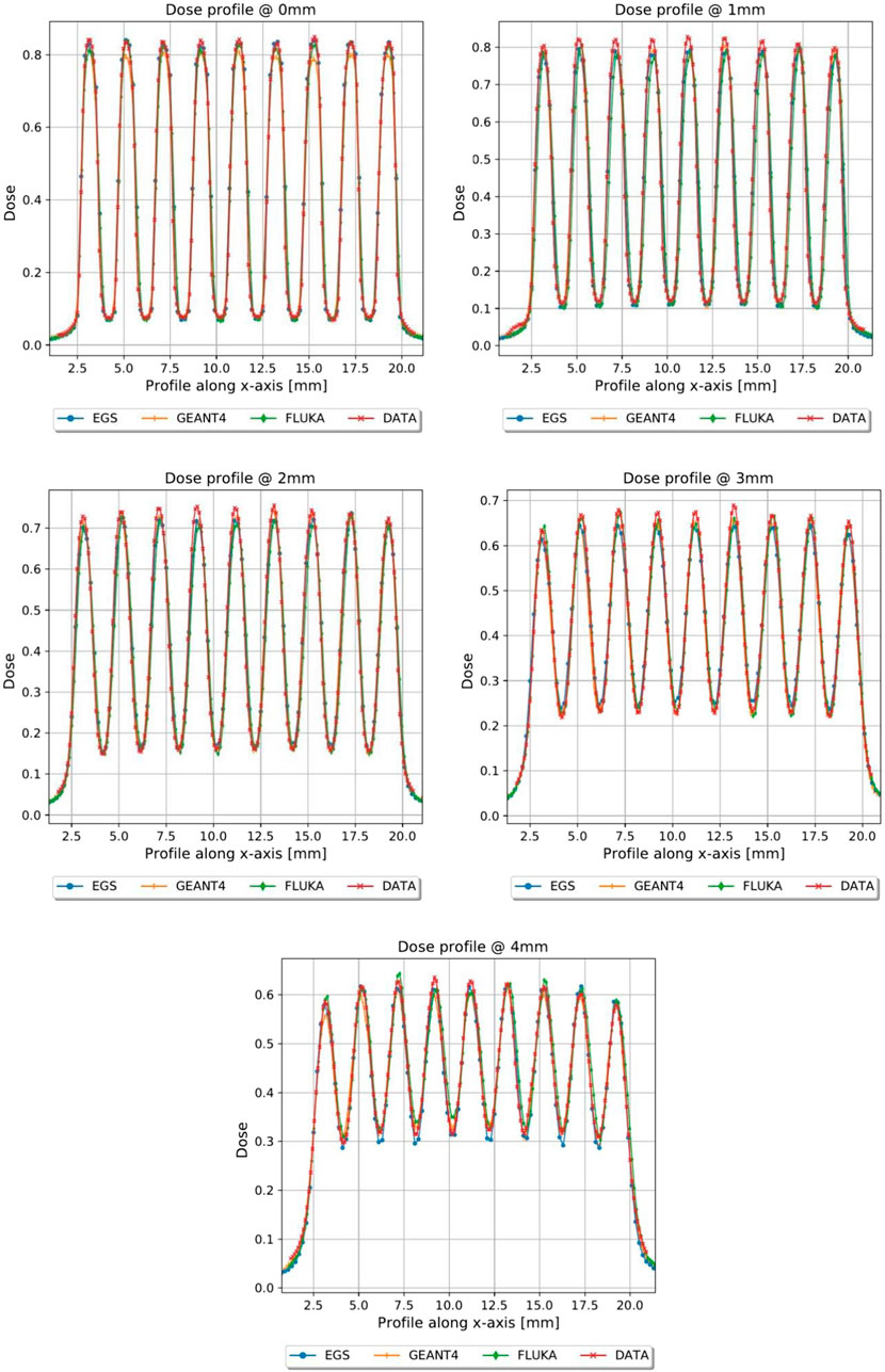
FIGURE 10. Dose profiles, normalized to the dose value of the open field at R100, of the first 4 mm in depth of planar_conf3, MC vs. GAF.
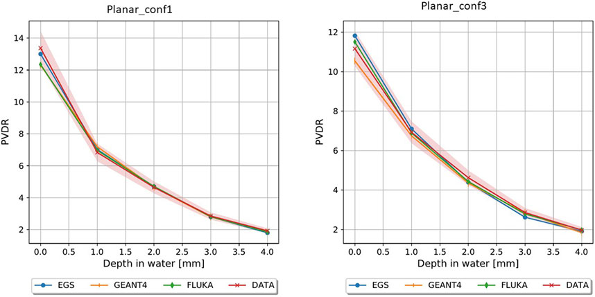
FIGURE 11. PVDR planar_conf1 (left) and planar_conf3 (right).
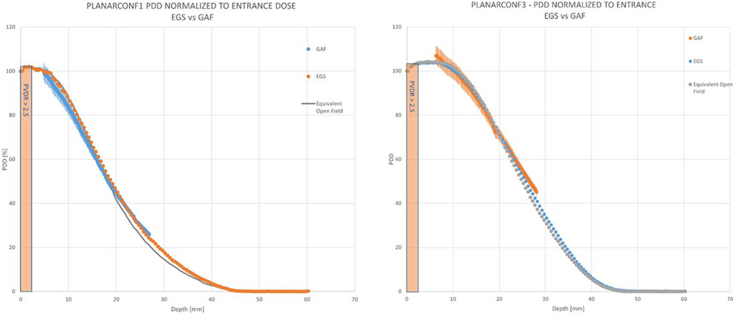
FIGURE 12. PDDs for the planar configurations. For planar_conf1 (left) the “mini-beam zone” extends up to 3 mm, which is the same as planar_conf3 (right).
In Table 2, the main mini-beam characteristics are reported for each constructed template. We reported, for each template and each depth, the PVDR, the ratio of the dose at the peak (D_p) and the dose at the buildup depth without the template (D_open, which is to be considered a reference dose value), the ratio of the dose at the valley (D_v) and D_open, the ratio of the average dose (D_avg) and D_open, the ctc, the FWHM and finally the R50 (which is the same for each template). For the sake of legibility, uncertainties on single dose measurements are assumed to be 4%, to be appropriately propagated for each derived quantity.
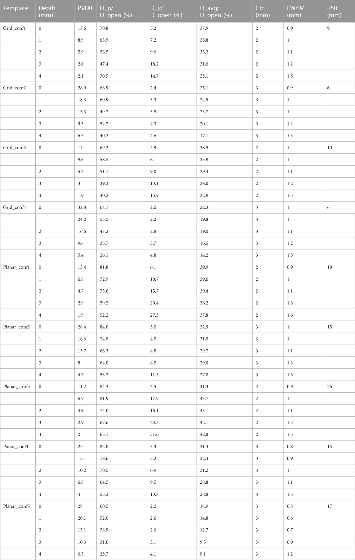
TABLE 2. Mini-beam characteristics for each template.
Finally, we present in Table 3 the possible parameters for mini-beam-conv and mini-beam-UHDR irradiation (Average dose rate (DR), dose per pulse (DPP) and dose rate within the pulse (DR_PULSE) at the peak and average mini-beam dose), at the reference depth of 1 mm, for the peak and average dose. All values are reported as ranges in square brackets, indicating the minimum (CONV) and maximum (FLASH) values achievable. These parameters are to be considered indicative, since we can tune the ElectronFlash to obtain a wide range of characteristics in a continuous way, within the limits of proper linac function.
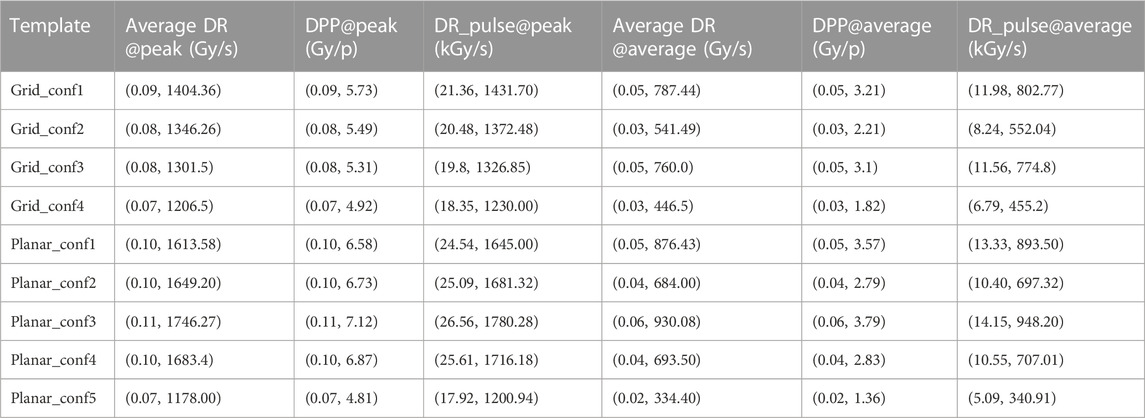
TABLE 3. MINI-BEAM-CONV and MINI-BEAM-FLASH characteristics for PEAK and AVERAGE dose points.
In this study, we have designed, simulated, and finally realized mini-beam and UHDR-mini-beams by using the triode-gun ElectronFlash low energy electrons linac and special tungsten passive template; we have then completely characterized dosimetrically our beams by means of radiochromic films. We have observed a good agreement between film measurements and Monte Carlo simulations. Due to the nature of radiochromic films, a greater discrepancy is the valley is to be expected with respect to the peaks, since the dose is much lower and the region of interest in which the dose is calculated is quite small. Nevertheless, the comparison with the simulations with various codes gave additional robustness to the experimental measurements. Across all Monte Carlo codes, the obtained results exhibited comparable outcomes with only minor discrepancies in valley dose. The relative dose values and PVDR measurements were in almost all cases within the uncertainty range of the gafchromic films, with discrepancies most likely due to different statistics and variation between the unique code parameters. Nevertheless, these findings affirm the capability of each of the evaluated codes to accurately simulate the linac geometry and templates. We have observed that increasing the ctc results in a decrease in the valley dose, leading to higher PVDR and a larger mini-beam zone. Having both grid and planar configurations at our disposal allows for great versatility in experiments. A grid configuration reduces dose deposition along the depth and enables a higher PVDR and mini-beam zone with fixed template parameters. This can be beneficial for in vivo irradiations for target up to 5–6 mm of size. On the other hand, the planar geometry diminishes the PVDR but achieves a higher peak dose and deeper dose penetration. This may be promising from a clinical perspective, as the beam does not lose penetration compared to the open field and has a mini-beam component in the first few mm of depth, which could substantially reduce side effects on the skin. Regarding bremsstrahlung contamination, even in the worst-case scenario, it is not significant within the mini-beam zone, and an appropriate mini-beam structure is maintained. This allows for the use of tungsten as the material of choice, at least in the case of low-energy electrons, as the main cause of mini-beam loss is primarily electron septa crossing, which is avoided due to the high atomic number (Z) of the material. Thus, the proposed method of generating a mini-beam structure offers great versatility. This versatility is particularly important when combined with the flash capabilities of our triode-gun ElectronFlash linac, as it enables the study of both mini-beam and flash effects by independently varying the fundamental spatial and temporal parameters involved in the two effets. This is fundamental for quantitative mini-beam and flash experiments, since we can vary all the fundamental parameters independently one from the other and without altering the experimental setup, guaranteeing a wide range of investigations and great reproducibility. The mini-beam and mini-beam-flash operating beams that we have realized, can be used to carry out radiobiological experiments necessary to study the quantitative dependencies of the flash and mini-beam effects and the beam parameters that characterize them, and to understand their underlying radiobiological mechanisms. These experiments are aimed at optimizing the clinical implementation of flash, mini-beam and possibly mini-beam flash radiotherapy. This will be fundamental also for the future transition to VHEE [48, 49], as mini-beams and the flash effect will play a crucial role. We are thus able to continue working towards a robust clinical protocol and evaluate the biological modifying factors necessary for a treatment planning system, both pre-clinical and clinical.
The original contributions presented in the study are included in the article/Supplementary Material, further inquiries can be directed to the corresponding author.
JP: Writing–original draft, Writing–review and editing. FR: Writing–review and editing. MC: Writing–review and editing. DS: Writing–review and editing. GFe: Writing–review and editing. GFr: Writing–review and editing. LM: Writing–review and editing. GM: Writing–review and editing. VP: Writing–review and editing. YP: Writing–review and editing. FD: Writing–review and editing.
The author(s) declare financial support was received for the research, authorship, and/or publication of this article. We thank Fondazione Pisa for funding CPFR with the grant “prog. n. 134/2021.” The research is also partially supported by INFN CSN5 funded project “FRIDA.” Additionally, the research has received funding from the European Union—NextGenerationEU through the Italian Ministry of University and Research under PNRR—M4C2-I1.3 Project PE_00000019 “HEAL ITALIA.”
Authors JP, GFe, and LM were employed by Sordina IORT Technologies S.p.A.
The remaining authors declare that the research was conducted in the absence of any commercial or financial relationships that could be construed as a potential conflict of interest.
All claims expressed in this article are solely those of the authors and do not necessarily represent those of their affiliated organizations, or those of the publisher, the editors and the reviewers. Any product that may be evaluated in this article, or claim that may be made by its manufacturer, is not guaranteed or endorsed by the publisher.
The views and opinions expressed are those of the authors only and do not necessarily reflect those of the European Union or the European Commission. Neither the European Union nor the European Commission can be held responsible for them.
1. Laissue JA, Blattmann H, Slatkin DN. “Alban Köhler (1874–1947): Erfinder der Gittertherapie.” Zeitschrift für Medizinische Physik (2012) 22 (2):90–99.
2. Schneider T, Prezado Y, Bertho A, Fazzari J, Iturri L, Martin OA, et al. Combining FLASH and spatially fractionated radiation therapy: the best of both worlds. Radiother Oncol (2022) 175(1):169–77. doi:10.1016/j.radonc.2022.08.004
3. Prezado Y. Divide and conquer: spatially fractionated radiation therapy. Expert Rev Mol Med (2022) 24:e3. doi:10.1017/erm.2021.34
4. Yan W, Khan MK, Wu X, Simone CB, Fan J, Gressen E, et al. Spatially fractionated radiation therapy: history, present and the future. Clin translational Radiat Oncol (2020) 20:30–8. doi:10.1016/j.ctro.2019.10.004
5. Bräuer-Krisch E, Serduc R, Siegbahn EA, Le Duc G, Prezado Y, Bravin A, et al. Effects of pulsed, spatially fractionated, microscopic synchrotron X-ray beams on normal and tumoral brain tissue. Mutat Research/Reviews Mutat Res (2010) 704(1-3):160–6. doi:10.1016/j.mrrev.2009.12.003
6. Prezado Y, Jouvion G, Hardy D, Patriarca A, Nauraye C, Bergs J, et al. Proton mini-beam radiation therapy spares normal rat brain: long-Term Clinical, Radiological and Histopathological Analysis. Scientific Rep (2017) 7:14403. doi:10.1038/s41598-017-14786-y
7. Prezado Y, Jouvion G, Guardiola C, Gonzalez W, Juchaux M, Bergs J, et al. Tumor control in RG2 glioma-bearing rats: a comparison between proton mini-beam therapy and standard proton therapy. Int J Radiat Oncology* Biology* Phys (2019) 104:266–71. doi:10.1016/j.ijrobp.2019.01.080
8. Girst S, Greubel C, Reindl J, Siebenwirth C, Zlobinskaya O, Walsh DW, et al. Proton mini-beam radiation therapy reduces side effects in an in vivo mouse ear model. Int J Radiat Oncology* Biology* Phys (2016) 95:234–41. doi:10.1016/j.ijrobp.2015.10.020
9. Lamirault C, Doyère V, Juchaux M, Pouzoulet F, Labiod D, Dendale R, et al. Short and long-term evaluation of the impact of proton mini-beam radiation therapy on motor, emotional and cognitive functions. Scientific Rep (2020) 10:13511. doi:10.1038/s41598-020-70371-w
10. Bertho A, Ortiz R, Juchaux M, Gilbert C, Lamirault C, Pouzoulet F, et al. First evaluation of temporal and spatial fractionation in proton mini-beam radiation therapy of glioma-bearing rats. Cancers (2021) 13:4865. doi:10.3390/cancers13194865
11. Mohiuddin M, Fujita M, Regine WF, Megooni AS, Ibbott GS, Ahmed MM. High-dose spatially-fractionated radiation (GRID): a new paradigm in the management of advanced cancers. Int J Radiat Oncol Biol Phys (1999) 45:721–7. doi:10.1016/s0360-3016(99)00170-4
12. Steel H, Brüningk SC, Box C, Oelfke U, Bartzsch SH. Quantification of differential response of tumour and normal cells to microbeam radiation in the absence of FLASH effects. Cancers (Basel) (2021) 13:3238. doi:10.3390/cancers13133238
13. Bouchet A, Brauer-Krisch E, Prezado Y, El Atifi M, Rogalev L, Le Clec’h C, et al. Better efficacy of synchrotron spatially microfractionated radiation therapy than uniform radiation therapy on glioma. Int J Radiat Oncol Biol Phys (2016) 95:1485–94. doi:10.1016/j.ijrobp.2016.03.040
14. Prezado Y, Deman P, Varlet P, Jouvion G, Gil S, Le Clec’H C, et al. Tolerance to dose escalation in mini-beam radiation therapy applied to normal rat brain: long-term clinical, radiological and histopathological analysis. Radiat Res (2015) 184:314–21. doi:10.1667/rr14018.1
15. Smyth LML, Donoghue JF, Ventura JA, Livingstone J, Bailey T, Day LRJ, et al. Comparative toxicity of synchrotron and conventional radiation therapy based on total and partial body irradiation in a murine model. Sci Rep (2018) 8:12044. doi:10.1038/s41598-018-30543-1
16. Martínez-Rovira I, Puxeu-Vaqué J, Prezado Y. Dose evaluation of Grid Therapy using a 6 MV flattening filter-free (FFF) photon beam: a Monte Carlo study. Med Phys (2017) 44(10):5378–83. doi:10.1002/mp.12485
17. Reiff JE, Huq MS, Mohiuddin M, Suntharalingam N. Dosimetric properties of megavoltage grid therapy. Int J Radiat Oncol Biol Phys (1995) 33(4):937–42. doi:10.1016/0360-3016(95)00114-3
18. Martínez-Rovira I, Fois G, Prezado Y. Dosimetric evaluation of new approaches in GRID therapy using nonconventional radiation sources. Med Phys (2015) 42(2):685–93. doi:10.1118/1.4905042
20. Prezado Y, Fois GR. Proton-mini-beam radiation therapy: a proof of concept. Med Phys (2013) 40:031712. doi:10.1118/1.4791648
21. Wright MD. Microbeam radiosurgery: an industrial perspective. Physica Med (2015) 31:601–6. doi:10.1016/j.ejmp.2015.04.003
22. Patriarca A, Fouillade C, Auger M, Martin F, Pouzoulet F, Nauraye C, et al. Experimental set-up for FLASH proton irradiation of small animals using a clinical system. Int J Radiat Oncology* Biology* Phys (2018) 102:619–26. doi:10.1016/j.ijrobp.2018.06.403
23. Peucelle C, Nauraye C, Patriarca A, Hierso E, Fournier-Bidoz N, Martínez-Rovira I, et al. Proton mini-beam radiation therapy: experimental dosimetry evaluation. Med Phys (2015) 42:7108–13. doi:10.1118/1.4935868
24. Schneider T. Technical aspects of proton mini-beam radiation therapy: mini-beam generation and delivery. Physica Med (2022) 100:64–71. doi:10.1016/j.ejmp.2022.06.010
25. Mohiuddin M, Lynch C, Gao M, Hartsell W. Early clinical results of proton spatially fractionated GRID radiation therapy (SFGRT). Br J Radiol (2020) 93:20190572. doi:10.1259/bjr.20190572
26. Felici G, Barca P, Barone S, Bortoli E, Borgheresi R, De Stefano S, et al. Transforming an IORT linac into a FLASH research machine: procedure and dosimetric characterization. Front Phys (2020) 8:374. doi:10.3389/fphy.2020.00374
27. Di Martino F, Del Sarto D, Giuseppina Bisogni M, Capaccioli S, Galante F, Gasperini A, et al. A new solution for UHDP and UHDR (Flash) measurements: theory and conceptual design of ALLS chamber. Physica Med (2022) 102:9–18. doi:10.1016/j.ejmp.2022.08.010
28. Marinelli M, di Martino F, Del Sarto D, Pensavalle JH, Felici G, Giunti L, et al. A diamond detector based dosimetric system for instantaneous dose rate measurements in FLASH electron beams. Phys Med Biol (2023) 68:175011. doi:10.1088/1361-6560/acead0
29. Morrocchi M, Pensavalle JH, Ciarrocchi E, Di Martino F, Felici G, Galante F, et al. Experimental characterization and Monte Carlo simulation of scintillator detectors in online electron FLASH radiotherapy dosimetry. J Instrumentation (2022) 17:P09005. doi:10.1088/1748-0221/17/09/p09005
30. Romano F, Milluzzo G, Di Martino F, D’Oca MC, Felici G, Galante F, et al. First characterization of novel silicon carbide detectors with ultra-high dose rate electron beams for FLASH radiotherapy. Appl Sci (2023) 13:2986. doi:10.3390/app13052986
31. Favaudon V, Caplier L, Monceau V, Pouzoulet F, Sayarath M, Fouillade C, et al. Ultrahigh dose-rate FLASH irradiation increases the differential response between normal and tumor tissue in mice. Sci translational Med (2014) 6(245):245ra93. doi:10.1126/scitranslmed.3008973
32. Vozenin MC, De Fornel P, Petersson K, Favaudon V, Jaccard M, Germond JF, et al. The advantage of FLASH radiotherapy confirmed in mini-pig and cat-cancer patients. Clin Cancer Res (2019) 25(1):35–42. doi:10.1158/1078-0432.ccr-17-3375
33. Montay-Gruel P, Petersson K, Jaccard M, Boivin G, Germond JF, Petit B, et al. Irradiation in a flash: unique sparing of memory in mice after whole brain irradiation with dose rates above 100 Gy/s. Radiother Oncol (2017) 124(3):365–9. doi:10.1016/j.radonc.2017.05.003
34. Agostinelli S, Allison J, Amako K, Apostolakis J, Araujo H, Arce P, et al. Geant4—a simulation toolkit. Nucl Instr Methods Phys Res Section A: Acc Spectrometers, Detectors Associated Equipment (2003) 506(3):250–303. ISSN 0168-9002. doi:10.1016/S0168-9002(03)01368-8
35. Soriani A, Iaccarino G, Felici G, Ciccotelli A, Pinnarò P, Giordano C, et al. Development and optimization of a beam shaper device for a mobile dedicated IOERT accelerator. Med Phys (2012) 39:6080–9. doi:10.1118/1.4749968
36. Ashland. EBTXD. https://www.ashland.com/industries/medical/radiotherapy-films/ebtxd (Accessed November 8, 2023).
37. Niroomand-Rad A, Chiu-Tsao S, Grams MP, Lewis DF, Soares CG, Van Battum LJ, et al. Report of AAPM task group 235 radiochromic film dosimetry: an update to TG-55. Med Phys (2020) 47:5986–6025. doi:10.1002/mp.14497
38. Kawrakow I, Rogers DWO, Mainegra-Hing E, Tessier F, Townson RW, Walters BRB. EGSnrc toolkit for Monte Carlo simulation of ionizing radiation transport (2000). [release v2021]. doi:10.4224/40001303
39. Böhlen TT, Cerutti F, Chin MPW, Fassò A, Ferrari A, Ortega PG, et al. The FLUKA code: developments and challenges for high energy and medical applications. Nucl Data Sheets (2014) 120:211–4. doi:10.1016/j.nds.2014.07.049
40. Ferrari A, Sala PR, Fasso` A, Ranft J. FLUKA: a multi-particle transport code (2005). CERN-2005-10, INFN/TC_05/11, SLAC-R-773.
41. Gianluca VR, Felici G, Galante F, Gasparini A, Kranzer R, Mariani G, et al. Application of a novel diamond detector for commissioning of FLASH radiotherapy electron beams. Med Phys (2022) 49:5513–22. doi:10.1002/mp.15782
42. Di Martino F, Del Sarto D, Bass G, Capaccioli S, Celentano M, Coves D, et al. Architecture, flexibility and performance of a special electron Linac dedicated to FLASH Radiotherapy research: ElectronFlash with a triode gun of the Centro Pisano Flash radiotherapy (CPFR). Front. Phys. (2023) 11:1268310. Accepted on 26 Oct 2023.
43. Di Martino F, Barca P, Barone S, Bortoli E, Borgheresi R, De Stefano S, et al. FLASH radiotherapy with electrons: issues related to the production, monitoring, and dosimetric characterization of the beam. Front Phys (2020) 8:570697. doi:10.3389/fphy.2020.570697
44. Abouzahr F, Cesar JP, Crespo P, Gajda M, Hu Z, Kaye W, et al. The first PET glimpse of a proton FLASH beam. Phys Med Biol (2023) 68:125001. doi:10.1088/1361-6560/acd29e
45. IEC 60601-2-1:2020. Medical electrical equipment - Part 2-1: particular requirements for the basic safety and essential performance of electron accelerators in the range 1 MeV to 50 MeV (2020). https://webstore.iec.ch/publication/31388 (Accessed November 8, 2023).
46. Low DA, Harms WB, Mutic S, Purdy JA. A technique for the quantitative evaluation of dose distributions. Med Phys (1998) 25:656–61. doi:10.1118/1.598248
47. NIST. National Institute of standards and Technology. https://physics.nist.gov/PhysRefData/Star/Text/ESTAR.html (Accessed November 8, 2023).
48. Sarti A, De Maria P, Battistoni G, De Simoni M, Di Felice C, Dong Y, et al. Deep seated tumour treatments with electrons of high energy delivered at FLASH rates: the example of prostate cancer. Front Oncol (2021) 11:777852. doi:10.3389/fonc.2021.777852
49. Muscato A, Arsini L, Battistoni G, Campana L, Carlotti D, De Felice F, et al. Treatment planning of intracranial lesions with VHEE: comparing conventional and FLASH irradiation potential with state-of-the-art photon and proton radiotherapy. Front Phys (2023) 11:1185598. doi:10.3389/fphy.2023.1185598
Keywords: mini-beam, flash, UHDR, UHDP, SFRT, passive collimation
Citation: Pensavalle JH, Romano F, Celentano M, Sarto DD, Felici G, Franciosini G, Masturzo L, Milluzzo G, Patera V, Prezado Y and Di Martino F (2023) Realization and dosimetric characterization of a mini-beam/flash electron beam. Front. Phys. 11:1269495. doi: 10.3389/fphy.2023.1269495
Received: 30 July 2023; Accepted: 03 November 2023;
Published: 16 November 2023.
Edited by:
Paweł Moskal, Jagiellonian University, PolandReviewed by:
Karol Lang, The University of Texas at Austin, United StatesCopyright © 2023 Pensavalle, Romano, Celentano, Sarto, Felici, Franciosini, Masturzo, Milluzzo, Patera, Prezado and Di Martino. This is an open-access article distributed under the terms of the Creative Commons Attribution License (CC BY). The use, distribution or reproduction in other forums is permitted, provided the original author(s) and the copyright owner(s) are credited and that the original publication in this journal is cited, in accordance with accepted academic practice. No use, distribution or reproduction is permitted which does not comply with these terms.
*Correspondence: Francesco Romano, ZnJhbmNlc2NvLnJvbWFub0BjdC5pbmZuLml0
Disclaimer: All claims expressed in this article are solely those of the authors and do not necessarily represent those of their affiliated organizations, or those of the publisher, the editors and the reviewers. Any product that may be evaluated in this article or claim that may be made by its manufacturer is not guaranteed or endorsed by the publisher.
Research integrity at Frontiers
Learn more about the work of our research integrity team to safeguard the quality of each article we publish.