- School of Electronic and Information Engineering, Anshun University, Anshun, China
Vibration induced by dry friction is ubiquitous in various engineering fields. To explore the vibration characteristics for further studies and/or controls, it is of great theoretical and practical significances to investigate the non-linear dynamic behaviors of the friction systems. This study considers the slight vibration of a two-degree-of-freedom non-linear dry friction excitation system. The differential equations of system motion are established according to Newton’s law of motion. Moreover, the system’s non-linear dynamic is studied when the block velocity is always less than the friction surface velocity. The results indicate that the linearized matrix of the vibration system has a pair of purely imaginary eigenvalues for some critical values of the relevant parameters. The Poincaré-Birkhoff normal forms are utilized to simplify the motion equation under the non-resonant assumption to obtain a simplified equation with only the resonant terms. Furthermore, the truncated part of the simplified equation is analyzed in the case of only linear terms degeneration. Finally, numerical simulations reflect some qualitative conclusions about the system’s local dynamic properties, including equilibrium point, periodic motion, torus motion, and their stability.
1 Introduction
There are numerous dry friction phenomena in engineering practice, including wheel-rail contact, locomotive braking systems, machine tool guides, tool cutting, drilling, and friction damping. Indeed, dry friction can cause surface wear and fatigue failure of mechanical components, and the resulting dynamic behavior (e.g., generating noises) harms production and living environments. The phenomenon of machine tools, drill pipe chatter, brake whistle, and other phenomena caused by dry friction excitation will cause severe problems in engineering. However, dry friction can dissipate system energy to achieve vibration reduction or stimulate the required motion state. Therefore, studying the motion law of objects under the dry friction action is particularly important for finding effective engineering control methods and effectively utilizing the dry friction phenomenon.
Leine et al. [1] investigated the existence and stability of the periodic solutions of the vector field in the case of continuous, non-smooth, and unique solutions, corresponding to the existence and stability of the periodic solution of the dry friction system in the pure slip state. Luo [2] established the Poincaré mapping of the dry friction system in the pure slip state and analyzed the system’s periodic motion and the mapping bifurcation. A specific periodic solution was obtained in the presence of adhesion by adjusting the parameters to satisfy the functional relationship on the vector field interface. The dry friction system’s periodic motion and chaos were studied by numerical simulations [3–5]. Guo et al. [6] established the Poincaré mapping of the single-degree-of-freedom dry friction vibrator based on the series solution of the differential equation and investigated the existence and stability of the system under 1:4 strength resonance for periodic and torus motions. Guo [7] investigated the existence and stability of subharmonic periodic and torus motions of single-degree-of-freedom dry friction vibrator under 1:5 weak resonance. When the amplitude of the vibration induced by the dry friction reached to some motion constraints, collisions will occur, which may result in complex non-linear dynamic phenomena, such as chaos and chaos control [8]. Refs. [9–14] present the researches of the collision system or the friction collision coexistence system. By applying the stroboscopic controlled hybrid Poincaré map and OGY control method, Gritli and Belghith [9] investigated the non-linear dynamic characteristic and chaos control of a one-degree-of-freedom impact oscillator with a single rigid constraint, in which the border-collision bifurcation is explored for the use of OGY-based state-feedback control method. A two-degree-of-freedom impact oscillator with dry friction and external periodically forced excitation is considered by Li et al. [10] based on the flow switchability theory and G-functions. A one-degree-of-freedom flexible-impact oscillator is investigated by Stefani et al. [11], where some possible dynamic scenarios were obtained by experimental tests and numerical simulations. In another paper by Stefani et al. [13], a comprehensive numerical study is conducted, where, compared to Ref. [11], the range of selected parameters were extended. Based on the numerical results in Ref. [13], Stefani et al. [12] investigated further the effect of gap size on the response of a one-degree-of-freedom flexible-impact oscillator, in which the secondary resonances were observed for quite small gap and the number of resonances were analyzed by changing the gap size. Peng and Fan [14] studied a three-degree-of-freedom rigid-impact oscillator with dry friction by using the flow switchability theory, and divided the six-dimensional phase space of the system into different domains and boundaries/edges. It can be seen from the above mentioned researches that numerical simulation and experimental method are the main means to explore the non-linear dynamic phenomena of system with friction and/or collision. Furthermore, in the previous studies, the bifurcation analysis after impact generally began with some periodic solution. To the best of the author’s knowledge, when the amplitude of torus motion reached to motion constraints and then collision occurs, the non-linear vibration characteristic (i.e., the bifurcation analysis after impact begin with some torus motion) is an open problem, which motivated the current study. As an initial investigation, only the periodic and torus motions within the smooth case are considered in this paper, which provides a theoretical basis for further analysis collision with motion constraints.
Non-linear vibrations are widely encountered in engineering practice. As one of the important characteristics of non-linear vibrations, the periodic and/or torus motions have attracted much attention [15–17]. Hopf-Hopf bifurcation is an approach to investigate the periodic and torus motions of dynamical system. Wen et al. [18] proposed a new Hopf-Hopf bifurcation criterion based on the coefficients of the original equation of dynamics for a dry friction system and the corresponding feedback control method was investigated. Guo et al. [19] investigated Hopf-Hopf bifurcation for a simplified railway wheelset model in the case of non-resonance and near-resonance, in which the resonant coefficients and the truncated Poincaré-Birkhoff normal form were computed by use of MATCONT [20]. A numerical analysis of Hopf-Hopf bifurcation for a non-linear electric oscillator in the case of 1:2 resonance was performed by Revel et al. [21], where the resonance could arise more non-trivial mode interactions and lead to more complex dynamical phenomena. Hopf-Hopf bifurcation can also be found in other dynamical systems, for instance in vibro-impact system [22], high-dimensional maps [23] and infinite dynamical system [24]. It is noted that in the above literature of Refs. [18, 19, 21, 24] concerning differential equations, the non-linear resonant terms either were computed numerically in which the analytical expressions cannot be given or were simplified by use of symmetry which cannot apply to asymmetric systems. For this reason, the expressions of non-linear resonant terms for a system without symmetry will be given analytically in the current paper.
By means of the Hopf-Hopf bifurcation theory, the periodic and torus motions of a two-degree-of-freedom dynamical system with dry friction are considered both analytically and numerically in this paper. This paper is organized as follows: In Section 2, the differential equation of the system motion is established according to Newton’s laws of motion, and the problem is confined to the “smooth motion” case. This means the block velocity is considered smaller than the friction surface velocity. Section 3 employs the Poincaré-Birkhoff normal forms to process the dynamic equation in Section 2 to obtain a simplified equation equivalent to the original dynamic equation, which only contains the resonant terms. Moreover, the calculation formulas of the resonant terms coefficients and the eigenvalues’ rate of change on the perturbated parameters are given analytically. In Section 4, the amplitude equation is studied with specific examples, and the conclusions of the existence and stability of the equilibrium point and periodic and torus motions of the original vibration system are investigated. Some conclusions and discussions are made in Section 5.
2 Mechanical model and motion equations
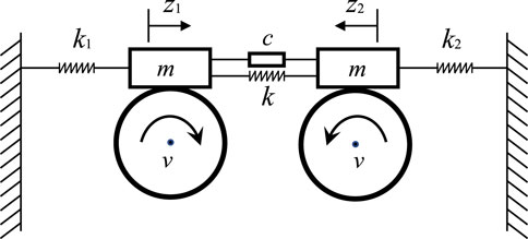
Figure 1 shows the schematic of a two-degree-of-freedom dry friction system [25].
The mass of each mass block is m, placed on two rotating circles. The speed of the circle’s edge is v. The remote ends of the two blocks are connected to the fixed end by springs with stiffness coefficients k1 and k2, respectively, and a spring-damping element is employed to connect the adjacent ends. The spring stiffness coefficient is k, and the damping coefficient is c. According to Newton’s law of motion, taking z1 and z2 as generalized coordinates, the following motion’s differential equation can be obtained:
where
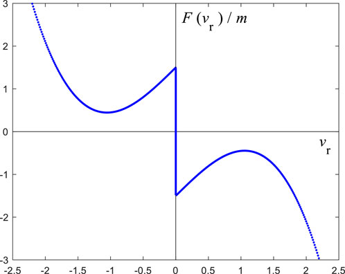
where vr is the relative velocity of the mass block relative to the edge of the wheel, and
This study considers that the relative velocity between the mass block and the edge of the wheel is always negative. Equivalently, a smooth vibration is considered. Thus, Eq. 2 can be written as:
Let
To perform coordinate translation, let
Hence, the origin is the system’s equilibrium position. Substituting Eq. 4 into Eq. 1 gives:
Let
where
let
To be sure, the highest order terms of Eq. 3 and Eq. 5 are cubic. Therefore, Taylor’s formula (6) for Eq. 5 are actually cubic polynomial rather than infinite series.
3 Normal form theory
Generally, the following differential equations are considered [26]:
where
where
Let
The non-linear terms in Eq. 8 can be represented with the following Taylor expansions with respect to the first four arguments:
Lemma 1 [26]: For the above system, if.
near the equilibrium point, Eq. 8 can be simplified to the following form through the reversible change of coordinates:
where
In relations (10–13), all
Lemma 2 [26]: Based on Lemma 1, if the following relations are satisfied.
Then, Eq. 9 can be transformed into the following form through coordinate transformation and modular, complex angle substitution:
where
In the case of simple degeneration, considering the truncated part of the modular equation in Eq. 14, we have
Accordingly, the primary motion forms of the system near the equilibrium position and their mutual transformations with parameter changes can be obtained. The orbit structure on a torus in Eq. 14 is generically different from that in the truncated Equation 15 due to phase locking. Nevertheless, for the non-resonance case [i.e., kω10≠lω20, (k, l > 0, k + l ≤ 5)] in this paper, the qualitative dynamical characteristics for Eq. 14 are the same as Eq. 15 from the observability point of view [26, p. 368].
In the proposed model, it can be seen that its linearized matrix
let
When
Consider the following transformation
where
By substituting Eq. 19 into Eq. 6, we have:
Let
By substituting the above equations into Eq. 21, the following plural form similar to Eq. 8 can be obtained:
Since only the case of linear terms degeneration is considered, it is only necessary to consider the first-order approximate expression of the eigenvalues’ real part
First, the coefficients of the cubic resonant terms are calculated. In order to obtain the resonant terms’ coefficients in normal form, take
Let
Now, when
Equation 27 is substituted into Eq. 21 and is transformed into the form of Eq. 24. According to Equations 10–13, one can obtain:
In order to calculate the first-order approximate expression of the real part
The corresponding
where
By differentiating Eq. 18 with respect to
Taking the inner product of
In consideration of the inner product definition, Eq. 35 can be written as
It follows from Eq. 32 that
In view of the inner product definition, Eq. 37 can be written as
From Eq. 33 and eliminating the terms
Taking the inner product of
Taken value at
Taking its real part, the change rate of
Specifically, let
From Eq. 16, we have:
Substituting equations (25-26) and (43–46) into Eq. 41, one can obtain:
4 Case study and Hopf-Hopf bifurcation
For the system shown in Figure 1, taking
It can be easily verified that it satisfies the non-resonance condition.
Let
From Eq. 52, we have
Substituting Eq. 52 into Eq. 42, one can obtain:
Substituting Equations (51) and (56) into Eq. 15, the specific form of Eq. 15 can be obtained. It is noted from Eqs. (51), (54) and (55) that the system undergoes Hopf-Hopf bifurcation in the “Simple” case [26]. Furthermore, since
From Eq. 51, it is easy to see
where
For all values of
If
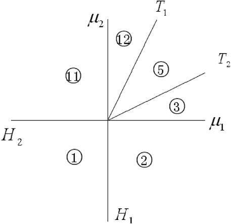
FIGURE 3. Parameter region division in Ref. [26] (corresponding to
If at least one of
and
the trivial equilibrium points
Specifically,
which is the area below
It should be noted that the “equilibrium point” at this time is the equilibrium point of the amplitude equation. Moreover, the non-trivial equilibrium point
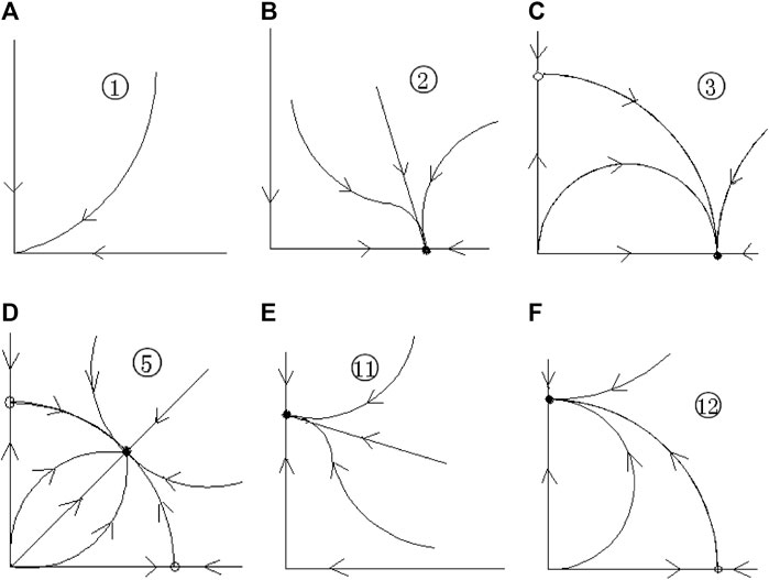
The phase trajectories corresponding to the parameter region
As shown in Figure 4, there is only a stable equilibrium point in region
According to equations (51) and (53), the specific form of Figure 3 can be drawn, as shown in Figure 5. Now,
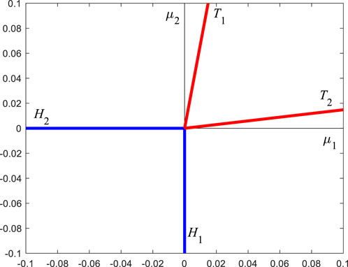
FIGURE 5. The specific form of Figure 3, determined by the specific parameters of this paper.
According to Eq. 56,
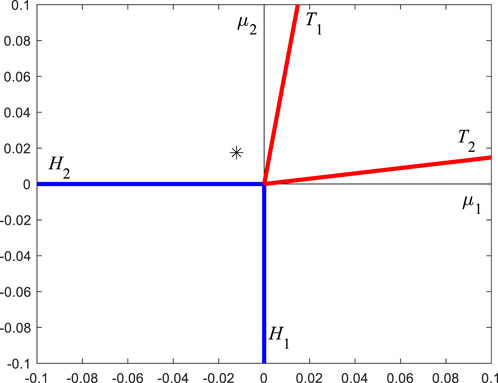
Take the first set of parameters:
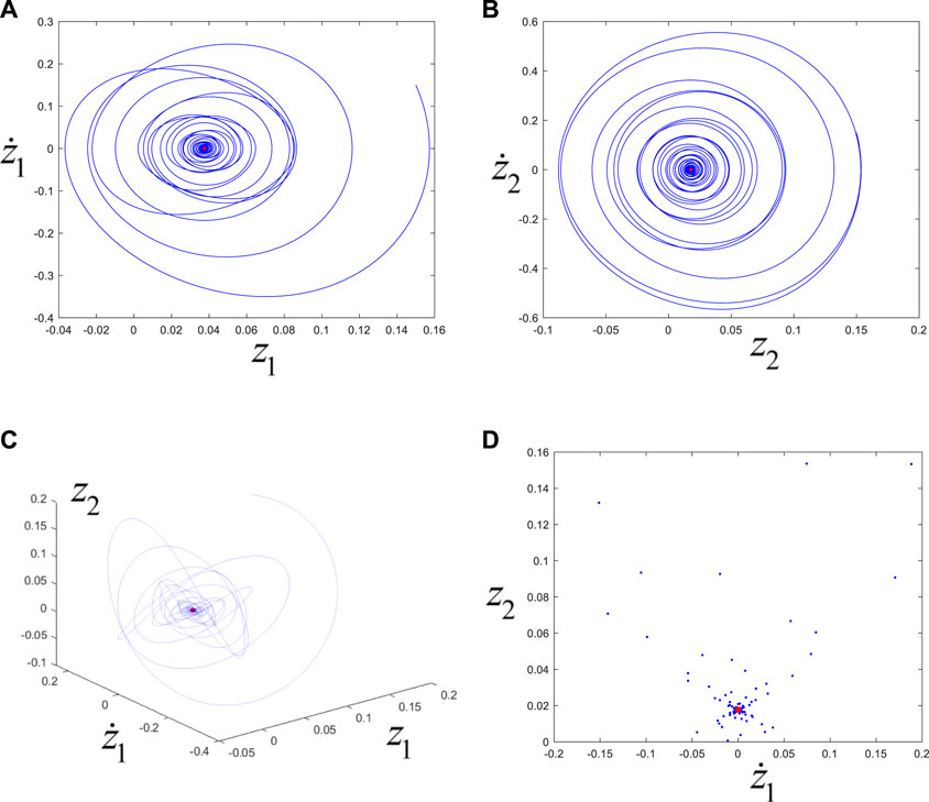
FIGURE 7. (A), (B), (C) are the phase trajectories, and (D) is the Poincaré map. The blue lines or points correspond to transient motions, and the red points correspond to steady-state motions (i.e., the final approach to the equilibrium position).
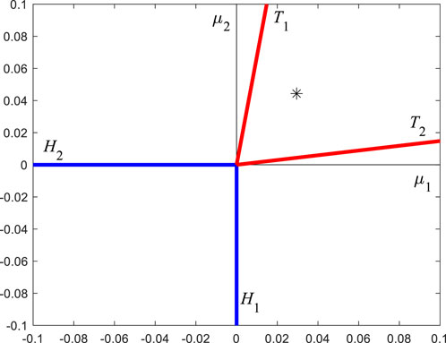
Take the second set of parameters:
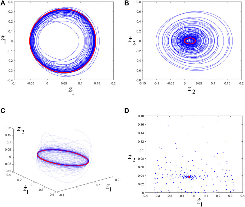
FIGURE 9. (A), (B), (C) are the phase trajectories, and (D) is the Poincaré map. The blue line or point corresponds to transient motion, and the red line or point corresponds to steady-state motion (i.e., eventually trending towards periodic motion).
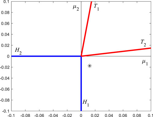
Take the third set of parameters:
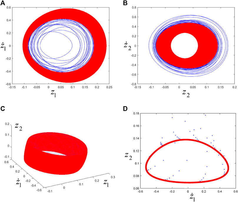
FIGURE 11. (A), (B), (C) are the phase trajectories, (D) is the Poincaré map. The blue line or point corresponds to the transient motion, and the red line or point corresponds to the steady-state motion (i.e., the final trend towards torus motion).
Take the fourth set of parameters:
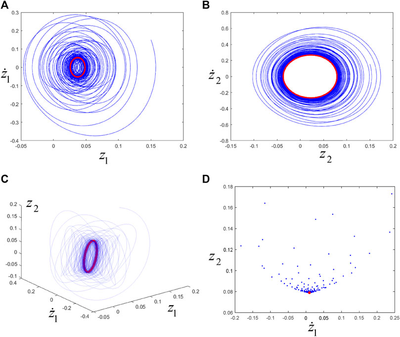
FIGURE 13. (A), (B), (C) are the phase trajectories, and (D) is the Poincaré map. The blue line or point corresponds to transient motion, and the red line or point corresponds to steady-state motion (i.e., eventually trending towards periodic motion).
In order to validate further the expressions (28–31, 47–50) and the analysis from Eq. 56 to Figure 5, the relevant numerical calculations for the system shown in Figure 1 are conducted with another set of parameters;
Let
From Eq. 61, we have
Substituting Eq. 61 into Eq. 42, one can obtain:
According to equations (60) and (62), the specific form of Figure 3 can be drawn, as shown in Figure 14. Now,
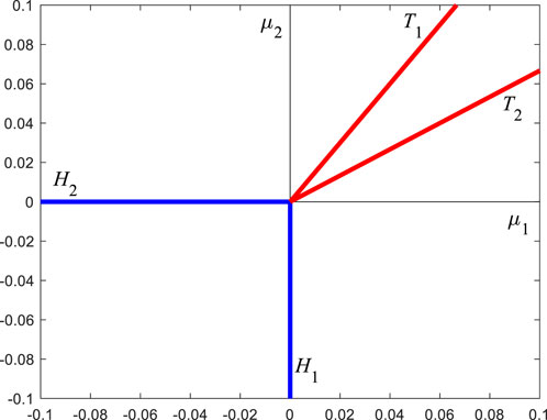
FIGURE 14. The specific form of Figure 3, determined by the specific parameters of this paper.
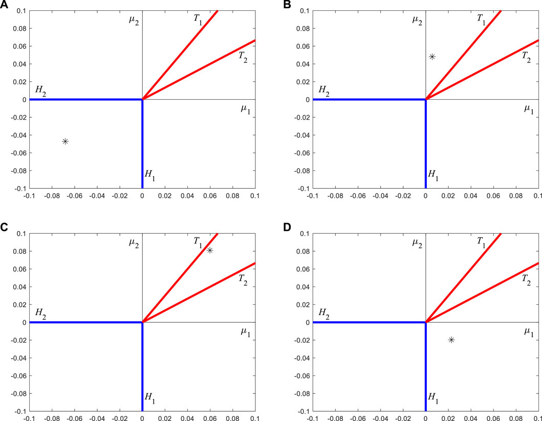
Taking four sets of parameters of
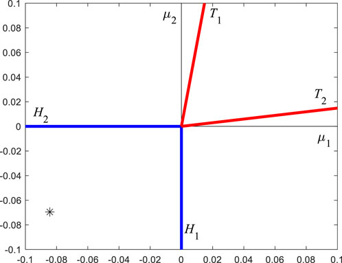
respectively, and their positions are represented by "*" in Figure 15.
According to the analysis from Eq. 56 to Figure 5, it can be seen from Figure 15A that the equilibrium position of system (1) is stable, and its phase trajectories and Poincaré map (with
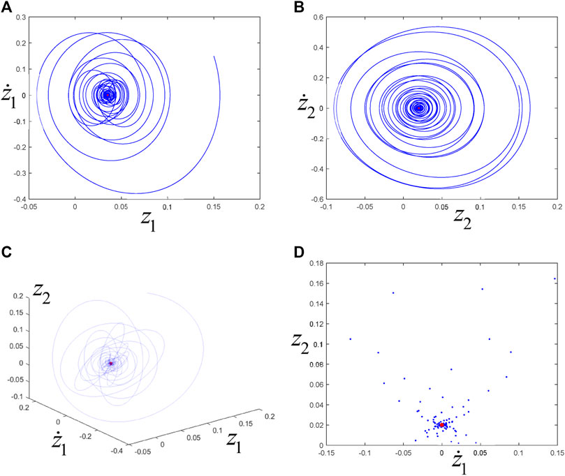
FIGURE 16. (A), (B), (C) are the phase trajectories, and (D) is the Poincaré map. The blue lines or points correspond to transient motions, and the red points correspond to steady-state motions (i.e., the final approach to the equilibrium position).
It is noted from Figure 15B that "*" belong to the area sandwiched by the blue and red lines. Then, system (1) has a stable periodic motion, and its phase trajectories and Poincaré map (with
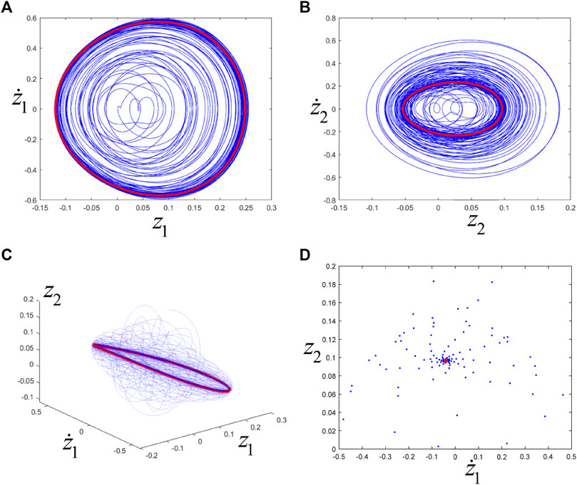
FIGURE 17. (A), (B), (C) are the phase trajectories, and (D) is the Poincaré map. The blue line or point corresponds to transient motion, and the red line or point corresponds to steady-state motion (i.e., eventually trending towards periodic motion).
The location of "*" in Figure 15C means that system (1) has a stable torus motion, where its phase trajectories and Poincaré map (with
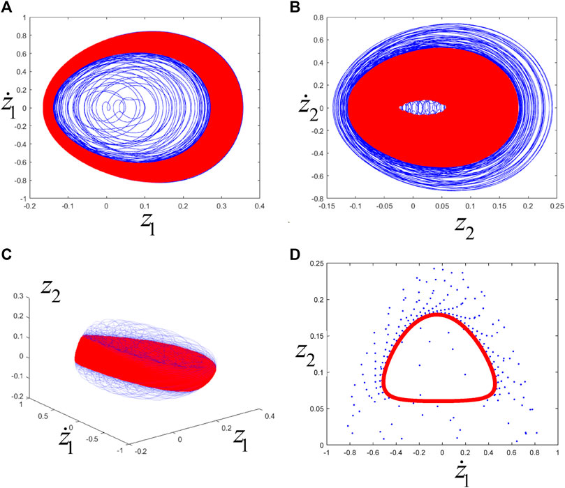
FIGURE 18. (A), (B), (C) are the phase trajectories, (D) is the Poincaré map. The blue line or point corresponds to the transient motion, and the red line or point corresponds to the steady-state motion (i.e., the final trend towards torus motion).
As shown in Figure 15D, "*" belong to the region sandwiched by the red and blue lines, which indicates that system (1) has a stable periodic motion, where its phase trajectories and Poincaré map (with
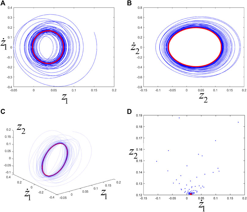
FIGURE 19. (A), (B), (C) are the phase trajectories, and (D) is the Poincaré map. The blue line or point corresponds to transient motion, and the red line or point corresponds to steady-state motion (i.e., eventually trending towards periodic motion).
5 Conclusions and discussions
5.1 Discussions
Comparing this paper with the previous works, the non-linear resonant terms are given analytically for a system without symmetry. In the previous studies: the non-linear resonant terms were not given and only the eigenvalues of linearization matrix and their derivatives were computed [18]; the non-linear resonant terms were obtained by numerical methods [19]; the non-linear resonant terms were derived analytically for a system with O (2) symmetry [24], where the non-linear resonant terms were simplified tremendously by the O (2) symmetry of the system. In the previous Ref. [18], the Hopf-Hopf bifurcation is “Subcritical” and the periodic and torus motions are unstable, where an inversion of time (i.e., t→-t) was needed for the visualization of the periodic and torus motions. However, the current paper gives an example of dynamical system in which “Supercritical” Hopf-Hopf bifurcation could occur; this complements the previous study.
In fact, the methods used in this paper can also be used to analyze the periodic and torus motions of high-dimensional systems. Nevertheless, before calculating the non-linear resonant terms, a longitudinal simplification is needed to reduce the high-dimensional systems to a set of four-dimensional ordinary differential equations, where the center manifold theory will be applied to obtain the reduced equations and the whole computational process could be tedious and numerical. For infinite dynamical systems, e.g., the analysis of vibration characteristics of structures with geometry non-linear caused by large deformation, the current methods are also applicable after reducing the non-linear partial differential equations to a set of four-dimensional ordinary differential equations. However, this process will be more difficult than that of high-dimensional system, which involved the two-point boundary values problem of linear partial differential equation and the projection of function spaces (see Ref. [24] as a simple example). Incidentally, the methods applied in this paper can accurately predict the qualitative dynamical behavior for systems having a pair of purely imaginary eigenvalues for some critical values of the relevant parameters. Nevertheless, the advantages are restricted to some neighborhood of the critical parameters values. Indeed, for the analysis of global bifurcations of mechanical systems, only using the current methods are inadequate.
In lemma 1, there is a non-resonant condition kω10≠lω20, (k, l > 0, k + l ≤ 5). If the eigenvalues ω10, ω20 fail to meet the non-resonant condition, i.e., kω10 equate or equate approximately to lω20 (k, l > 0, k + l ≤ 5), richer dynamical phenomena will happen. Meanwhile, the normal form (9) will become more difficulty and the differential equations in regard to argument variables ϕ1, ϕ2 in Eq. 14 should be considered. For this, the detailed analysis remains to be further studied in the future. Some numerical investigations for two kinds of resonant cases are given in what follows.
Case 1. ω10 = 2ω20. Taking
They do not satisfy the non-resonance condition because ω10 = 2ω20 (k, l > 0, k + l = 3 ≤ 5). Take the set of parameters:
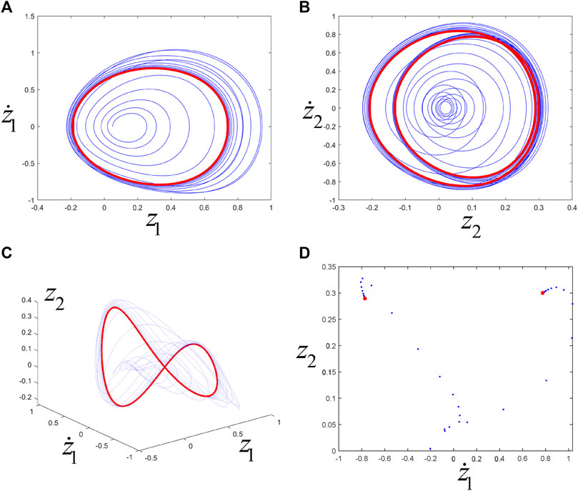
FIGURE 20. (A), (B), (C) are the phase trajectories, and (D) is the Poincaré map. The blue line or point corresponds to transient motion, and the red line or point corresponds to steady-state motion (i.e., eventually trending towards periodic motion).
Case 2. 2ω10 ≈ 3ω20. Taking
They do not satisfy the non-resonance condition because 2ω10 ≈ 3ω20 (k, l > 0, k + l = 5 ≤ 5). Take the set of parameters:
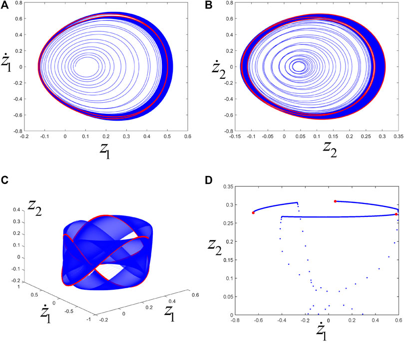
FIGURE 21. (A), (B), (C) are the phase trajectories, and (D) is the Poincaré map. The blue line or point corresponds to transient motion, and the red line or point corresponds to steady-state motion (i.e., eventually trending towards periodic motion).
5.2 Conclusions
This paper studied the periodic and torus motions of a two-degree-of-freedom dynamical system with dry friction by theoretical analysis and numerical simulations in the non-resonance case. The Poincaré-Birkhoff normal form was calculated analytically, and the simplified equations were obtained. The analysis of the simplified equations reflected stable periodic and torus motions for suitable parameter regions. Numerical simulations were compatible with the theoretical results. The novelty of this paper is focused on the analytical calculations of non-linear resonant terms for the current asymmetric mechanical system and the discovery of “Supercritical” Hopf-Hopf bifurcation.
Data availability statement
The raw data supporting the conclusion of this article will be made available by the authors, without undue reservation. All authors contributed to the article and approved the submitted version.
Author contributions
The author confirms being the sole contributor of this work and has approved it for publication.
Funding
This work was supported by the National Natural Science Foundation of China [12002096] and the 2022 Doctoral Foundation of Anshun University (asxybsjj202201).
Conflict of interest
The author declares that the research was conducted in the absence of any commercial or financial relationships that could be construed as a potential conflict of interest.
Publisher’s note
All claims expressed in this article are solely those of the authors and do not necessarily represent those of their affiliated organizations, or those of the publisher, the editors and the reviewers. Any product that may be evaluated in this article, or claim that may be made by its manufacturer, is not guaranteed or endorsed by the publisher.
References
1. Leine RI, Nijmeijer H. Dynamics and bifurcations of non-smooth mechanical systems. New York: Springer-Verlag (2004).
2. Luo ACJ. Discontinuous dynamical systems on time-varying domains. Beijing: Higher Education Press and Springer-Verlag (2009).
3. Galvanetto U. Dynamics of a three DOF mechanical system with dry friction. Phys Lett A (1998) 248:57–66. doi:10.1016/s0375-9601(98)00644-6
4. Stefański A, Wojewoda J, Wiercigroch M, Kapitaniak T. Chaos caused by non-reversible dry friction. Chaos, Solitons and Fractals (2003) 16:661–4. doi:10.1016/s0960-0779(02)00451-4
5. Bellido F, Ramírez-Malo JB. Periodic and chaotic dynamics of a sliding driven oscillator with dry friction. Int J Non-Linear Mech (2006) 41:860–71. doi:10.1016/j.ijnonlinmec.2006.05.004
6. Guo Y, Xie JH. Neimark-Sacker (N-S) bifurcation of oscillator with dry friction in 1:4 strong resonance. Appl Math Mech (2012) 34:27–36. doi:10.1007/s10483-013-1650-9
7. Guo Y. Torus and subharmonic motions of a forced vibration system in 1 : 5 weak resonance. Adv Math Phys (2020) 2020:1–9. doi:10.1155/2020/5017893
8. Karami H, Mobayen S, Lashkari M, Bayat F, Chang A. LMI-Observer-Based stabilizer for chaotic systems in the existence of a nonlinear function and perturbation. Mathematics (2021) 9:1128. doi:10.3390/math9101128
9. Gritli H, Belghith S. Diversity in the nonlinear dynamic behavior of a one-degree-of-freedom impact mechanical oscillator under OGY-based state-feedback control law: Order, chaos and exhibition of the border-collision bifurcation. Mechanism Machine Theor (2018) 124:1–41. doi:10.1016/j.mechmachtheory.2018.02.001
10. Li C, Fan J, Yang Z, Xue S. On discontinuous dynamical behaviors of a 2-DOF impact oscillator with friction and a periodically forced excitation. Mechanism Machine Theor (2019) 135:81–108. doi:10.1016/j.mechmachtheory.2019.01.020
11. Stefani G, De Angelis M, Andreaus U. Scenarios in the experimental response of a vibro-impact single-degree-of-freedom system and numerical simulations. Nonlinear Dyn (2020) 103:3465–88. doi:10.1007/s11071-020-05791-4
12. Stefani G, De Angelis M, Andreaus U. Influence of the gap size on the response of a single-degree-of-freedom vibro-impact system with two-sided constraints: Experimental tests and numerical modeling. Int J Mech Sci (2021) 206:106617. doi:10.1016/j.ijmecsci.2021.106617
13. Stefani G, De Angelis M, Andreaus U. Numerical study on the response scenarios in a vibro-impact single-degree-of-freedom oscillator with two unilateral dissipative and deformable constraints. Commun Nonlinear Sci Numer Simulation (2021) 99:105818. doi:10.1016/j.cnsns.2021.105818
14. Peng Y, Fan J. Discontinuous dynamics of a class of 3-DOF friction impact oscillatory systems with rigid frame and moving jaws. Mechanism Machine Theor (2022) 175:104931. doi:10.1016/j.mechmachtheory.2022.104931
15. Wang J, Shan Za., Chen S. Bifurcation and chaos analysis of gear system with clearance under different load conditions. Front Phys (2022) 10. doi:10.3389/fphy.2022.838008
16. Han X, Bi X, Sun B, Ren L, Xiong L. Dynamical analysis of two-dimensional memristor cosine map. Front Phys (2022) 10. doi:10.3389/fphy.2022.911144
17. Akram S, Nawaz A, Yasmin N, Ghaffar A, Baleanu D, Nisar KS. Periodic solutions of some classes of one dimensional non-autonomous equation. Front Phys (2020) 8. doi:10.3389/fphy.2020.00264
18. Wen G, Xu H, Xie J. Controlling Hopf–Hopf interaction bifurcations of a two-degree-of-freedom self-excited system with dry friction. Nonlinear Dyn (2010) 64:49–57. doi:10.1007/s11071-010-9844-x
19. Guo P, Huang C, Zeng J, Cao H. Hopf–Hopf bifurcation analysis based on resonance and non-resonance in a simplified railway wheelset model. Nonlinear Dyn (2022) 108:1197–215. doi:10.1007/s11071-022-07274-0
20. Dhooge A, Govaerts W, Kuznetsov YA. Matcont: A MATLAB package for numerical bifurcation analysis of ODEs. ACM Trans Math Softw (Toms) (2003) 37:141–64. doi:10.1145/779359.779362
21. Revel G, Alonso DM, Moiola JL. Numerical semi-global analysis of a 1:2 resonant Hopf–Hopf bifurcation. Physica D: Nonlinear Phenomena (2013) 247:40–53. doi:10.1016/j.physd.2012.12.007
22. Xie J, Ding W. Hopf–Hopf bifurcation and invariant torus of a vibro-impact system. Int J Non-Linear Mech (2005) 40:531–43. doi:10.1016/j.ijnonlinmec.2004.07.015
23. Wen G-L, Xu D. Feedback control of Hopf–Hopf interaction bifurcation with development of torus solutions in high-dimensional maps. Phys Lett A (2004) 321:24–33. doi:10.1016/j.physleta.2003.12.005
24. Guo Y, Xie J, Wang L. Three-dimensional vibration of cantilevered fluid-conveying micropipes—types of periodic motions and small-scale effect. Int J Non-Linear Mech (2018) 102:112–35. doi:10.1016/j.ijnonlinmec.2018.04.001
Keywords: dry friction, normal form, bifurcation, equilibrium, periodic motion, torus motion
Citation: Guo Y (2023) Periodic and torus motions of a two-degree-of-freedom dry friction vibration system. Front. Phys. 11:1188002. doi: 10.3389/fphy.2023.1188002
Received: 16 March 2023; Accepted: 11 April 2023;
Published: 09 May 2023.
Edited by:
Jacques Kengne, University of Dschang, CameroonReviewed by:
Zhouchao Wei, China University of Geosciences Wuhan, ChinaTianhu Yu, Luoyang Normal University, China
Copyright © 2023 Guo. This is an open-access article distributed under the terms of the Creative Commons Attribution License (CC BY). The use, distribution or reproduction in other forums is permitted, provided the original author(s) and the copyright owner(s) are credited and that the original publication in this journal is cited, in accordance with accepted academic practice. No use, distribution or reproduction is permitted which does not comply with these terms.
*Correspondence: Yong Guo, Z3ktZ2F0ZXNAMTYzLmNvbQ==
 Yong Guo