
94% of researchers rate our articles as excellent or good
Learn more about the work of our research integrity team to safeguard the quality of each article we publish.
Find out more
ORIGINAL RESEARCH article
Front. Phys., 17 February 2023
Sec. Interdisciplinary Physics
Volume 11 - 2023 | https://doi.org/10.3389/fphy.2023.1135739
This article is part of the Research TopicAdvances in Nonlinear Systems and NetworksView all 13 articles
As the product of a circuit’s voltage and current, apparent power (S) is of paramount necessity and importance in electrical utilities, electronics, communication, and neural network systems. Based on the existing AC power analysis on the two-terminal passive elements (i.e., R, L, and C), some in-depth research on AC apparent power calculations for second-order memory elements and memristive systems is introduced to help with revealing their complex and unique non-linear phenomena. This paper derives the forms of real power, reactive power, and apparent power for the proposed second-order memory elements (i.e., MR, MC, and ML) and reveals the difference between ideal memory elements and traditional passive ones (i.e., R, C, and L). For all involved memory elements, harmonic values and an extra term occur in the expression of powers to represent their memory characteristics. Especially, the real power is a function of a circuit’s dissipative elements (usually resistances R), but not exactly the memristor (MR). Then, the corresponding curves could be depicted, which demonstrate the differences between R/C/L and MR/MC/ML and verified that harmonic values existed in SMR/SMC/SML, meaning that it would perpetually supply energy when operated with an alternating current.
Since the memristor was founded by L. O Chua in 1971 [1] and fabricated by HP Laboratories in 2008 [2,3], the notion of the MR was expanded to encompass ‘memristive systems’ and has demonstrated that the existence of a fingerprint (known as the ‘pinched hysteresis loop’) is the sufficient condition of a memory system [1,4]. Subsequently, memcapacitor (MC, abbreviation of ‘memory capacitor’) and meminductor (ML, abbreviation of ‘memory inductor’) were postulated in 1978 [2,3]. Up to now, plenty of memristive systems with different memory elements have been implemented. In the field of neural systems and networks, in 2015, both single-associative memory and multi-associative memories based on a memristive Hopfield network have been realized with memristors and memristive systems [5]. In 2019, a novel synaptic unit with double identical memristors and its neural network circuit architecture was built to update the weight matrices [6]. In 2020, C Y Lin and his co-workers demonstrated one resistive random-access memory with a novel memristor to mimic biological synapses, which offered a multi-bit functionality and synaptic plasticity for simulating various strengths in neuronal connections [7]. In 2021, spiking and burst phenomena were successfully simulated based on memristor circuits [8]. In 2022, Juan Pablo Carbajal and his co-workers introduced a training algorithm for a memristor network, which has been implemented in the hardware [9]. Also, Yi and his team reported an activity-difference-based training on co-designed tantalum oxide analog memristor crossbars, which has been termed memristor activity-difference energy minimization and trained one-layer and multilayer neural networks that can classify Braille words with high accuracy [10]. Then, Sun and his team proposed a multimode generalization and differentiation circuit for the Pavlov associative memory based on memristors [11]. Also, Liao M et al. realized the associative memory neural network and the gradual learning, gradual forgetting, and gradual transferring processes of emotions and designed a memristor-based circuit of the affective associative memory neural network [12]. Based on the memristive Hopfield neural network, neural bursting and synchronization have been imitated by modeling two neural network models [13]. Moreover, the famous Hodgkin−Huxley neuron model with a memristor [14] and firing mechanism for both single memristive neuron and double memristive coupled neurons [15] have been built. From the aforementioned works, it has been widely recognized that memristors have been successfully employed to configure neurons and synapses in a series of neuromorphic circuits.
In the field of emulator and oscillation circuits, the following non-linear behaviors have been founded, such as spiking and bursting oscillation [8,16], coexistent and hidden attractors [17,18], two-parameter bifurcations [8,19], chaotic dynamics [20,21], memristive diode bridge-coupled oscillator [22], neural oscillation [23,24], and the unified floating and grounded mem-element emulator [3,3]. Furthermore, there are some other applications. For example, in memory computing, both charge-based and resistance-based memory devices are used to analyze their physical attributes [25]. In the machine learning and neuromorphic hardware, the memristor has been applied for proving the effectiveness for edge detection [16]. In the privacy protection of medical data [26], image encryption [27], and audio encryption application [28], multi-scroll memristive Hopfield neural networks have played an important role. In 2011, D Biolek et al. presented is a proof that the ‘non-crossing-type pinched hysteretic loops’ phenomenon cannot occur in ideal memory elements, which are defined axiomatically via corresponding constitutive relations or via other equivalent characteristics and pointed that the ‘crossing-type hysteretic loop’ is one of their typical fingerprints [29,30]. In 2020, Guo Z et al introduced a phasor analysis method for memory elements to help with the understanding of complex non-linear phenomena in circuits with a memristor, memcapacitor, meminductor, and second-order memristor [31]. In 2021, the expression of equivalent admittance and impedance connected in parallel and series memristive circuits were derived [32], which are still in their infancy. Also, these existing researches have opened new realms for non-linear circuit investigations.
The second-order memristor, such as the ideal HP memory elements, could be considered as one of the most closely related ways to reflect the constitutive relationship of a physical memristor and are also the keys to developing a new generation of intelligent and neuromorphic devices. There are few pieces of literature that involve power analysis for these memory elements. Although some effort has been applied and published in AC circuit analyses, they are not sufficient in obtaining entry characteristics for an electric circuit in practical engineering. For the sake of the completeness of the non-linear electric circuit theory, power analyses and calculations should be given more and more attention. In this paper, based on constitutive relationships, some in-depth research on AC power calculations for memory elements are introduced to help in revealing their complex and unique non-linear phenomena and memory features. The difference between ideal second-order memory elements (i.e., MR, MC, and ML) and traditional passive ones (i.e., R, C, and L) is presented according to the forms of apparent powers for them. For all involved memory elements, harmonic values and an extra term occur in the expression of apparent power to represent their memory characteristics. Especially, the real power equals the apparent power for a resistor (R), which is the positive value, but this result is not available for the memristor (MR) in the unit of Ohm (Ω). Moreover, observed from the curves of PR/QC/QL and SMR/SMC/SML, harmonic values exist in all expressions of apparent power. These harmonic (and negative) values represent that it would perpetually supply energy when operated with an alternating current.
The remainder of this paper is organized as follows: in Section II, the background on the apparent power for basic 2-terminal passive elements (i.e., R, L, and C) and a brief introduction on ideal memory elements are presented. Then, three apparent power models for an ideal memristor (MR), memcapacitor (MC), and meminductor (ML) are derived in Section III. In Section V, the apparent power for the combination of memory elements is fully studied and analyzed. Finally, the conclusions are summarized in Section VI.
Based on the circuit theory, instantaneous power (P(t)) could be defined as the product of the instantaneous voltage v(t) across the element and instantaneous current i(t) through the load element. The combination of real power and reactive power is called apparent power, without a reference to the phase angle. In a simple circuit with the passive element, the applied current
where variables vR, vC, and vL present the voltages; SR, SC, and SL are the apparent powers; PR, QC, and QL stand for the real power for a resistor (R) and reactive powers for both the capacitor (C) and inductor (L), respectively.
Then, considering a current source (i) is applied as the input excitation, setting the parameters (I = 1A, ω = 0.002 rad/s, θ = π/6, R = 2Ω, C = 40F, and L = 30H), the following curves of instantaneous voltage (vR(t), vC(t), or vL(t)) and instantaneous power (PR(t), QC(t), or QL(t)) are drawn in Figure 1.
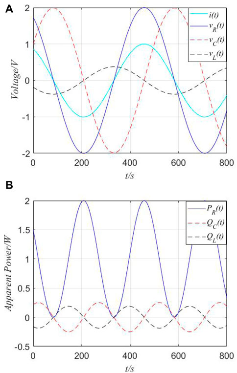
FIGURE 1. Instantaneous voltage and instantaneous power in the time domain. (A) Instantaneous voltage in the time domain. (B) Instantaneous power in the time domain.
From Figure 1, the instantaneous real power (PR(t)) is always positive, and reactive power (QC(t) and QL(t)) may be positive or negative values.
Next, AC power analysis should be present, which is of paramount importance that involves the transmission of power from one point to another. It could be considered as a basic and useful technique for analyzing circuits with AC signals.
Recalling from physics, the phasor-domain representation of impedances for passive elements (i.e., R, L, and C) can be given as follows:
We consider a practical circuit network, which is the arbitrary combination of passive elements under sinusoidal excitations, as shown in Figure 2.
Both the voltage and current at the terminals of the network can be described as follows:
where both variables I and U present amplitudes (or peak values); θi and θv stand for phase angles of the voltage and current, respectively.
Thus, instantaneous power for the network is computed as follows:
From Eq. 4, there are two terms in the form of instantaneous power. The first part is a sinusoidal function whose frequency is 2ω, which is twice the angular frequency of the voltage or current, plus the sum of the phase of the voltage and current. The second one is time independent, which depends upon the phase difference between the voltage and current.
Practically, instantaneous power is difficult to measure. Also, the value measured by the wattmeter is the average power, which shows the average of instantaneous power over a period of time and is given by
where Pavg means the average of power. It has two integrals. The first integral is a sinusoid. The average of this sinusoid over a period of time is zero. The second integral term is constant. Thus, average power can be denoted as
Subsequently, based on the concept of the effect value or the root of the mean of the square of the AC signal, the effect value of power (Prms) can be written as follows:
Moreover, in order to clearly show the related concepts on load impedance
where real power (P = Prms = Pavg) is delivered to a load in watts, which is the only useful and actual power dissipated by the load. Reactive power (Q) is related to the energy exchange between the source and the reactive part of the load.
According to the concepts of memristors in [1], there are three mathematical representations of the time-invariant ones, which have been named as extended memristor, generic memristor, and ideal memristor; each one has two forms depending on whether the input signal is a current source (current-controlled memristor) or a voltage source (voltage-controlled memristor). In this section, we focus on one of the specific cases based on the constitutive relationship, i.e., the ideal second-order memristor (MR), second-order memcapacitor (MC), and second-order meminductor (ML).
Considering a charge-controlled memristor for an ideal second-order one, its constitutive relationship can be described analytically by a proposed cubic polynomial:
where φ and q are the accumulated flux and charge, respectively; a11 and b11 are the two parameters; R represents the initial memristance in Ohm (Ω).
The pinched hysteresis loop occurs at the origin (v, i) = (0, 0) and is depicted in Figure 3A. The Lissajous figures of v−i for
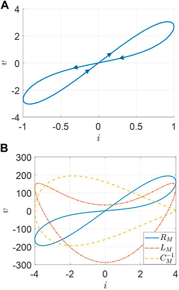
FIGURE 3. Pinched hysteresis loop and Lissajous figure of v−i. (A) Pinched hysteresis loop of an ideal memristor. (B) v−i for the inverse memcapacitance and meminductance.
Also, the proposed ideal second-order memristance R(q) can be calculated as follows:
Then, constitutive relations and notions of the ideal second-order memcapacitor and meminductor can be expanded as follows:
where Cm and Lm stand for the memcapacitance and meminductance, respectively; φ and q are the time-domain integrals of u and i, respectively; a12, b12, a13, and b13 are the parameters; both C and L represent the initial memcapacitance in farad (F) and meminductance in henry (H).
Both pinched hysteresis loops occur at the origin (v, i) = (0, 0) and are depicted in Figure 4.
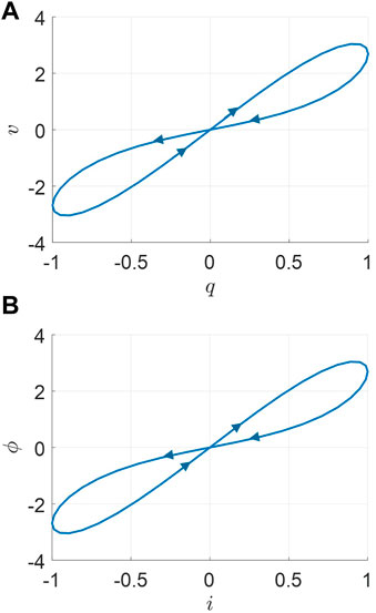
FIGURE 4. Pinched hysteresis loops. (A) Double-valued Lissajous figure of q(t) and v(t) for an ideal second-order memcapacitor. (B) Double-valued Lissajous figure of i(t) and ϕ(t) for an ideal second-order meminductor.
From Figure 3 and Figure 4, ‘crossing-type hysteretic loops’ are exhibited as one of their typical fingerprints for ideal memory elements [4].
We consider a non-linear circuit which is a combination of a memory element and several resistors under sinusoidal excitation. It is tested with bipolar periodic input sinusoidal signals, which result in a periodic sinusoidal response with a different frequency. Both the resistor and memristor have the unit of Ohm, and the “in-phase” relationship could be found for the purely resistive circuit, but different conclusions could occur for the non-linear circuit with a memory element. As mentioned in the previous section, this section begins by defining and deriving the apparent power for this special non-linear circuit with only one memory element, as shown in Figure 5.

FIGURE 5. Memristive system with a memory element and several resistors excited by a sinusoidal source.
For a charge-controlled ideal second-order memristor (see Eq. 9), we assume that the applied current source is
where the variables i and vMR with the period t could be presented in the form of the Fourier series; I,
Then, instantaneous power PMR(t) for a memristor in Figure 5 could be also defined as the product of instantaneous voltage vMR(t) across this element and the instantaneous current i(t) through it, given as follows:
where the variable PMR is also presented in the form of the Fourier series;
Moreover, the average value of memristor instantaneous power over on period can be given as follows:
where PavgMR has two terms. The first one is a non-linear function with frequency instead of the constant for purely resistive circuits. The second integer term is a sinusoid, which equals to zero over a period of time. Therefore, memristor average power could be denoted as
Furthermore, as mentioned in the concept of the effect value of power (PrmsMR), it can be derived as follows:
where PrmsMR has two parts. The first part is a constant which is similar to the effect power of the resistor. The second one is a non-linear function, which could change with the frequency affecting the memristive circuit effect power.
According to the concepts in the circuit theory, for an AC purely resistive circuit, the current and voltage are in-phase and power at any instant can be found by multiplying the voltage by the current at that instant, and because of this “in-phase” relationship, P(t) and Prms(t) values can be used to find the equivalent DC power or heating effect.
and
While comparing the instantaneous power between (PR) and (PMR) (see Eq. 15) and effect power between (PrmsR) and (PrmsMR) (see Eq. 16), there is an extra term in each equation; they are unpublished and important special variables that change with the frequency. Both of them can be considered as key points in exhibiting memory characteristics for a memristor.
Hereby, when a current source (i) is applied through this memory element, the parameters (I = 3A, ω = 1.5 rad/s, θ = π/6, R = 2, b11 = 2, and a11 = 2), curves of the current (i(t)), voltage (vMR(t)), and instantaneous powers (PR(t) and PMR(t)) are shown in Figure 6.
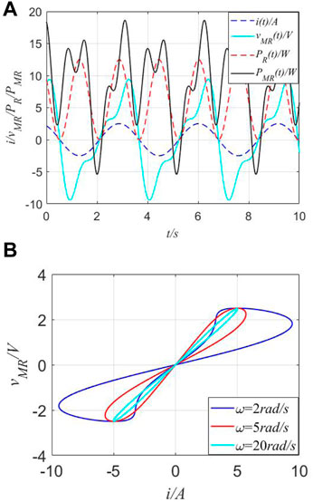
FIGURE 6. Different curves of instantaneous power in the time domain and fingerprint of MR. (A) Curves of the current (i(t)), voltage (vMR(t)), and instantaneous powers (PR(t) and PMR(t)). (B) Pinched hysteresis loops of the ideal MR.
From Figure 6, multiple frequencies between the input signal (i(t))/response signal (vMR(t)) and instantaneous power (PR(t) and PMR(t)) are observed. Also, the existence of fingerprints for the proposed MR could be verified. For a traditional resistor (R), when the current source i(t) is applied through R = 2Ω, it is absorbed power in watts (W) and can be illustrated through red-dotted lines, which present the twice frequency relationship between i(t) and PR(t). Complex curves of vMR(t) and PMR(t) demonstrate unique memory characteristics by negative values, i.e., the negative value would mean that it would perpetually supply energy when operated with an alternating current. However, according to concepts of real power for a resistor, it should always be a positive value. Thus, real power is not suitable for defining the features of an MR or memristive system, with apparent power being applied (SMR(t)).
Furthermore, in general electrical engineering, the power factor (abbreviated as pf) of an AC power system is defined as the ratio of the real power absorbed by the load to the apparent power flowing in the circuit. Real power is the average of the instantaneous product of voltage and current and represents the capacity of electricity for performing the work. Therefore, there are the following relations: 1) Q = 0 for resistive loads (unify pf); 2) Q < 0 for capacitive loads (leading pf); 3) Q > 0 for inductive loads (lagging pf). However, from Figure 6A, both positive and negative values exist in instantaneous power (PMR(t)), instead of only the positive values in real instantaneous power (PR(t) in Figure 1B).Here, there are two meanings: One means that the perpetual supply energy could occur to keep its unique memory characteristics and the other implies that the effect of the power factor disappeared in such types of circuits and only the definition of apparent power is still working.
For a φ-controlled (φ denotes the time-domain integral of the voltage) ideal second-order memcapacitor (see Eq. 10) and applied voltage source
where the variables v and iMC with the period t can be presented in the form of the Fourier series;
In an AC circuit, the product of voltage and current is expressed as volt-ampere (VA) and is known as apparent power, symbol “S”. Also, the “in-phase” relationship between the current and voltage exists for an AC purely resistive circuit. However, if the circuit contains reactive components, the voltage and current waveforms will be “out-of-phase” by some amount determined by the circuit’s phase angle. If the phase angle between the voltage and current is at its maximum of π/2, the volt-ampere product will have equal positive and negative values. In other words, there is also another power component that is present whenever there is a phase angle. This component is called reactive power (sometimes referred to as imaginary power) and is expressed in a unit called “volt-amperes reactive”, (Var), and symbol “Q.” When the reactive circuit returns as much power to the supply as it consumes, it results in the average power consumed by the circuit becoming zero. Then, the expression of active power P(t) and Prms = UrmsIrms is no longer suitable. These reactive components include the capacitor, inductor, and memory elements (i.e., memcapacitor and meminductor). Also, both MC and ML are not considered as new fundamental circuit elements (Liu, 2020b).
Then, instantaneous reactive power QMC(t) could be defined as the product of the instantaneous voltage v(t) across this element and the instantaneous current iMC(t) through it, given as follows:
where the variable QMC is also presented in the form of the Fourier series;
While comparing instantaneous reactive powers between (QC(t)) and (QMC(t)), there is an extra term in Eq. (19), which is unpublished and important because special variables change with the frequency. They could be considered as key points for exhibiting memory characteristics for the memcapacitor.
When the phase angle between the voltage and current is at its maximum of π/2, the relationship can be given as follows:
Next, for an φ-controlled memcapacitor, when a voltage source (v) is applied through MC, the parameters (U = 1.5A, ω = 3 rad/s, θ = π/6, C = 0.7, a12 = 1.3, and b12 = −1.3), the curves of voltage (v(t)), current (iMC(t)), and instantaneous reactive powers between (QC(t)) and (QMC(t)) are depicted in Figure 7.
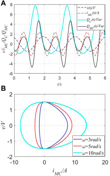
FIGURE 7. Different curves of instantaneous power in the time domain and fingerprint of MC. (A) Curves of v(t), iMC(t), and QC(t) and QMC(t) in the time domain. (B) Pinched hysteresis loops of the ideal MC.
As observed from Figure 7, multiple frequencies between the input signal (v(t))/response signal (iMC(t)) and instantaneous powers (QC(t) and QMC) are observed. Then, the existence of fingerprints for the constructed MC could be verified. For one traditional capacitor (C), when the voltage source v(t) is applied cross C = 0.7F, its reactive power can be represented through a cyan-solid line, which presents the twice frequency relationship between v(t) and QC(t). Complex curves of iMC(t) and QMC(t) demonstrate unique memory characteristics through negative values with the unit of volt-ampere reactive (Var).
Similar to the description on MC and motivated by the aforementioned analysis on the ideal ML, for a q-controlled ideal meminductor (see Eq. 10) and applied current source
where the I and VML with the period t can be presented in the form of the Fourier series.
Then, instantaneous reactive power QML(t) can be derived as follows:
where
The instantaneous reactive power between (QL(t)) and (QML(t)) (see Eq. 23) is computed as follows:
where two extra negative terms exist in QL(t) and QML(t), which are important special variables and change with the frequency. They can be considered as key points in exhibiting memory characteristics for the meminductor.
When the phase angle between the voltage and current is at its maximum of π/2, the relationship can be given as follows:
Setting the parameters (I = 1A, ω = 3 rad/s, θ = π/6, L = 0.8, b13 = 3, and a13 = 2), curves of voltage (vm(t)) and instantaneous reactive power (QML(t)) are shown in Figure 8.
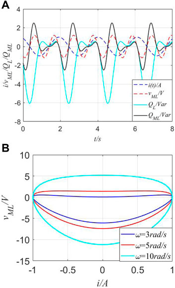
FIGURE 8. Instantaneous values in the time domain and fingerprint of ML. (A) Instantaneous values of the current (i(t)), voltage (vML(t)), and instantaneous reactive powers (QL(t) and QML(t)) in the time domain. (B) Pinched hysteresis loops of the ideal ML.
Observed from Figure 8, similar to MR and MC, multiple frequencies are verified. Then, the fingerprint of the MC does exist. For a traditional inductor (L), when the current source i(t) is applied through L = 0.8H, its reactive power can be represented through a cyan-solid line, which presents the twice frequency relationship between i(t) and vML(t). Complex curves of vML(t) and QML(t) demonstrate unique memory characteristics with the negative volt-ampere product.
When a specific circuit is built by an AC source and a combination of the proposed memory elements, its apparent power could be expressed by a function of the circuit’s total memory impedance (ZM). In the previous section, the true power or reactive power is discussed for MR, MC, and ML, respectively. According to the definition of impedance
where
Hereby, a series-connected combination of all memory elements denoted as (ZM) is designed in Figure 9.
When a series-connected circuit with an unknown combination of memory elements is configured, the following four special cases occur, and they are analyzed and discussed in this section. A typical situation for the first case is the combination of MR, MC, and ML. Then, parameter values are fixed as I = 1.5A, ω = 3 rad/s, θ = π/6, R = 2, C = 0.07, L = 0.5, a11 = 2, b11 = 2, a12 = 1.3, b12 = −1.3, a13 = 2, and b13 = 2; the v−i curves, v(t) curves, and apparent powers in the time domain are shown in Figure 10.
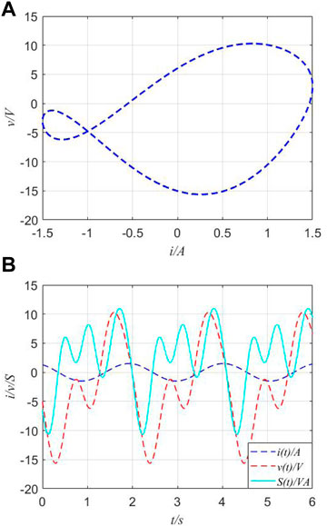
FIGURE 10. v−i curves and apparent power of series-connected circuits. (A) v−i curves of the series-connected combination of MR, MC, and ML. (B) Voltage and apparent power in the time domain.
In Figure 10, the v−i curve of
A typical situation for the second case is the combination of MR and MC; the v−i curves, v(t) curves, and apparent power are shown in Figure 11. For convenience, the parameter values of memory elements used in this case are exactly the same as the ones in the last case.
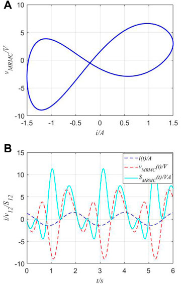
FIGURE 11. v−i curves and apparent power of series-connected circuits. (A) v−i curves of the series-connected combination of MR and MC. (B) Voltage and apparent power in the time domain.
In Figure 11, the v−i curve of
The combination of MR and ML is a typical situation for the third case as shown in Figure 12. Its v−i of ZM = ZMR + ZML curves is a triangle frisbee-like loop surrounding the origin.
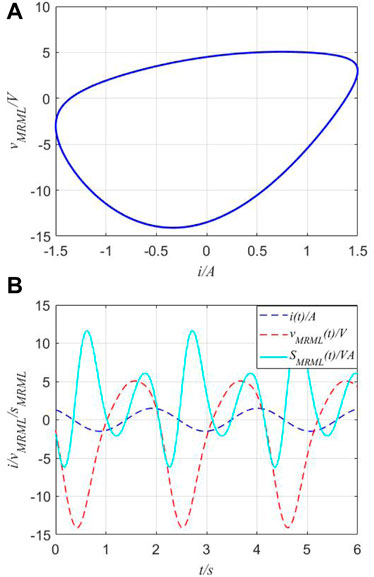
FIGURE 12. v−i curves and apparent power of series-connected circuits. (A) v−i curves of the series-connected combination of MR and ML. (B) Voltage and apparent power.
The combination of MC and ML is a typical situation for the fourth case; the v−i curves and apparent power are shown in Figure 13.
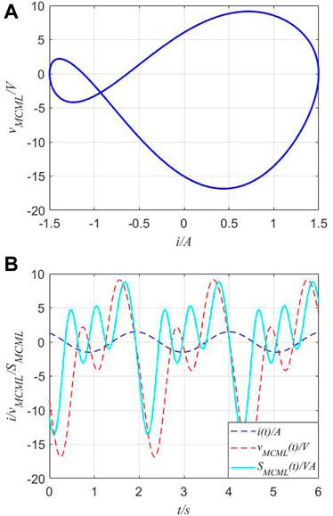
FIGURE 13. v−i curves and apparent power of the series-connected circuit. (A) v−i curves of the series-connected combination of MR and ML. (B) Voltage and apparent power.
In practice, some different or same types of multiple memory elements can be connected together, and the combination of the memory elements is very complex. Hereby, four typical situations are introduced and discussed to illustrate the physical characteristics of v−i and apparent powers, which could conveniently help in analyzing non-linear behaviors and finding phenomena of the combination of the proposed second-order memristor, memcapacitor, and meminductor. The theoretical analysis of the combination problem of memory elements can conveniently reveal whether some traditional definitions and rules are still available for these memory elements. This method can also be suitable for the physical connection problem when the connected memory elements operate nearly in their ideal ranges.
Since memory elements have been considered as the key for developing the new generation of intelligent devices postulated by some researchers, some neuromorphic systems and basic memristive circuits should become one of the hotspots, such as for physical expression and power analysis. According to the concepts on constitutive relationships, ideal second-order memory elements are proposed; their expressions of current/voltage are derived according to the input excitation. Then, the difference between ideal second-order memory elements (i.e., MR, MC, and ML) and traditional passive ones (i.e., R, C, and L) is presented according to forms of true power, reactive power, and apparent power for them. Moreover, the corresponding curves in the time domain are depicted. Observed from the curves of PR/QC/QL and SMR/SMC/SML, harmonic (and negative) values exist in all expressions of apparent power. These harmonic values represent that they would perpetually supply energy when operated with an alternating current. Finally, a series-connected circuit with an unknown combination of memory elements is configured; the v−i curves, voltages, and apparent power of four special cases are shown in detail. For memristive circuits, analyses show that the traditional relationship of the lead and lag between the current and voltage is not available and is difficult to be described by any existing rule. Their apparent power presents diversity, but it could not be simply attributed to an individual expression by any certain memory element or traditional component.
The original contributions presented in the study are included in the article/Supplementary Materials; further inquiries can be directed to the corresponding author.
YL, FL, and AW contributed to the conception and design of the study. WL and HL organized the database. YL wrote the first draft of the manuscript. All authors contributed to manuscript revision and read and approved the submitted version.
This work was supported in part by three Science and Technology Projects of Jilin Province under grant nos 20210201105GX, 202522YY010173621, and 20220204090YY.
The authors declare that the research was conducted in the absence of any commercial or financial relationships that could be construed as a potential conflict of interest.
All claims expressed in this article are solely those of the authors and do not necessarily represent those of their affiliated organizations, or those of the publisher, the editors, and the reviewers. Any product that may be evaluated in this article, or claim that may be made by its manufacturer, is not guaranteed or endorsed by the publisher.
1. Chua LO. If it’s pinched it’s a memristor. Semiconductor Sci Tech (2014) 49(10):104001. doi:10.1088/0268-1242/29/10/104001
2. Liu Y, Iu HH. Novel floating and grounded memory interface circuits for constructing mem-elements and their applications. IEEE Access (2020) 8(1):114761–72. doi:10.1109/ACCESS.2020.3004160
3. Liu Y, Iu HH, Guo Z, Si G. The simple charge-controlled grounded/floating mem-element emulator. IEEE Trans Circ Syst.–II: Express Briefs (2020) 68(6):2177–81. doi:10.1109/TCSII.2020.3041862
4. Chua LO. Resistance switching memories are memristors. Appl Phys A (2011) 102:765–83. doi:10.1007/s00339-011-6264-9
5. Hu SG, Liu Y, Liu Z, Chen TP, Wang JJ, Yu Q, et al. Associative memory realized by a reconfigurable memristive Hopfield neural network. Nat Commun (2015) 6(1):7522–8. doi:10.1038/ncomms8522
6. Wang C, Xiong L, Sun J, Yao W. Memristor-based neural networks with weight simultaneous perturbation training. Nonlinear Dyn (2019) 95(4):2893–906. doi:10.1007/s11071-018-4730-z
7. Lin CY, Chen J, Chen PH, Chang TC, Wu Y, Eshraghian JK, et al. Adaptive synaptic memory via lithium-ion modulation in RRAM devices. Small (2020) 16(42):2003964. doi:10.1002/smll.202003964
8. Innocenti G, Di MM, Tesi A, Forti M. Memristor circuits for simulating neuron spiking and burst phenomena. Front Neurosci (2021) 2021:681035. doi:10.3389/fnins.2021.681035
9. Carbajal JP, Martin DA, Chialvo DR. Learning by mistakes in memristor networks. Phys Rev E (2022) 105(5):054306. doi:10.1103/PhysRevE.105.054306
10. Yi S, Kendall JD, Williams RS, Kumar S. Activity-difference training of deep neural networks using memristor crossbars. Nat Elect (2022) 2022:1–7. doi:10.1038/s41928-022-00869-w
11. Sun J, Wang Y, Liu P, Wen S, Wang Y. Memristor-based neural network circuit with multimode generalization and differentiation on pavlov associative memory. IEEE Trans Cybernetics (2022) 2022:1–12. doi:10.1109/TCYB.2022.3200751
12. Liao M, Wang C, Sun Y, Lin H, Xu C. Memristor-based affective associative memory neural network circuit with emotional gradual processes Neural Computing and Applications. Neural Comput Appl (2022) 34:1–16. doi:10.1007/s00521-022-07170-z
13. Lin H, Wang C, Chen C, Zhou C, Xu C, Hong Q, et al. Neural bursting and synchronization emulated by neural networks and circuits. IEEE Trans Circ Syst.I: Regular Pap (2021) 68(8):3397–410. doi:10.1109/TCSI.2021.3081150
14. Liu Y, Iu HHC, Qian Y. Implementation of Hodgkin-Huxley neuron model with the novel memristive oscillator. IEEE Trans Circ Syst Express Briefs (2021) 68(8):2982–6. doi:10.1109/TCSII.2021.3066471
15. Shen H, Yu F, Wang C, Sun J, Cai S. Firing mechanism based on single memristive neuron and double memristive coupled neurons. Nonlinear Dyn (2022) 110:3807–22. doi:10.1007/s11071-022-07812-w
16. Mannion DJ, Mehonic A, Ng WH, Linderman RW, Kenyon AJ. Memristor-based edge detection for spike encoded pixels. Front Neurosci (2020) 13:1386. doi:10.3389/fnins.2019.01386
17. Wang X, Yu J, Jin C, Iu HHC, Yu S. Chaotic oscillator based on memcapacitor and meminductor. Nonlinear Dyn (2019) 96:161–73. doi:10.1007/s11071-019-04781-5
18. Wang X, Gao M, Iu HHC, Wang C. Tri-valued memristor-based hyper-chaotic system with hidden and coexistent attractors. Chaos Solitons and Fractals (2022) 159:112177. doi:10.1016/j.chaos.2022.112177
19. Sadecki J, Marszale W. Complex oscillations and two-parameter bifurcations of a memristive circuit with diode bridge rectifier. Microelectronics J (2019) 93(1):104636. doi:10.1016/j.mejo.2019.104636
20. Liu Y, Iu HHC, Guo S, Li H. Chaotic dynamics in memristive circuits with different ϕ - q characteristics. Int J Circuit Theor Appl (2021) 49(11):3540–58. doi:10.1002/cta.3112
21. Xu KD, Li D, Jiang Y, Chen Q. SPICE behaviors of double memristor circuits using cosine window function. Front Phys (2021) 9:648737. doi:10.3389/fphy.2021.648737
22. Bao B, Wu P, Bao H, Chen M, Xu Q. Chaotic bursting in memristive diode bridge-coupled Sallen-Key lowpass filter. Elect Lett (2017) 53(16):1104–5. doi:10.1049/el.2017.1647
23. Liu Y, Li H, Guo SX, Iu HHC. Generation of multi-lobe Chua corsage memristor and its neural oscillation. Micromachines (2022) 13(8):1330. doi:10.3390/mi13081330
24. Wang X, Zhou P, Jason K, Eshraghian H, Lin C, Iu HHC, et al. High-density memristor-CMOS ternary logic family. IEEE Trans Circuits Systems–I: Regular Pap (2021) 68(1):264–74. doi:10.1109/TCSI.2020.3027693
25. Marszalek W. Autonomous models of self-crossing pinched hystereses for mem-elements. Nonlinear Dyn (2018) 92(4):1975–83. doi:10.1007/s11071-018-4175-4
26. Yu F, Shen H, Yu Q, Kong X, Sharma PK, Cai S. Privacy protection of medical data based on multi-scroll memristive Hopfield neural network. IEEE Trans Netw Sci Eng (2022) 2022:1–14. doi:10.1109/TNSE.2022.3223930
27. Yu F, Kong X, Mokbel AAM, Yao W, Cai S. Complex dynamics, hardware implementation and image encryption application of multiscroll memeristive Hopfield neural network with a novel local active memeristor. IEEE Trans Circ Syst.–II: Express Briefs (2022) 70:326. doi:10.1109/TCSII.2022.3218468
28. Yu F, Yu Q, Chen H, Kong X, Mokbel AAM, Yao W, et al. Dynamic Analysis and audio encryption application in IoT of a Multi-Scroll fractional-order memristive Hopfield neural network. Fractal and Fractional (2022) 6(7):370. doi:10.3390/fractalfract6070370
29. Biolek D, Biolek Z, Biolkova V. Pinched hysteretic loops of ideal memristors, memcapacitors and meminductors must be ’self-crossing. Elect Lett (2011) 47(25):1385–7. doi:10.1049/el.2011.2913
30. Biolek Z, Biolek D, Biolkova V. Hysteresis versus PSM of ideal memristors, memcapacitors, and meminductors. Elect Lett (2016) 52(20):1669–71. doi:10.1049/el.2016.2138
31. Guo Z, Iu HHC, Si G, Xu X, Oresanya BO, Bie Y. A phasor analysis method for charge-controlled memory elements. Int J Bifurcation Chaos (2020) 30(14):2030041. doi:10.1142/S0218127420300414
Keywords: memristor, apparent power, reactive power, memcapacitor, meminductor
Citation: Liu Y, Liu F, Luo W, Wu A and Li H (2023) AC power analysis for second-order memory elements. Front. Phys. 11:1135739. doi: 10.3389/fphy.2023.1135739
Received: 01 January 2023; Accepted: 16 January 2023;
Published: 17 February 2023.
Edited by:
Hairong Lin, Hunan University, ChinaReviewed by:
Ho Ching Iu, University of Western Australia, AustraliaCopyright © 2023 Liu, Liu, Luo, Wu and Li. This is an open-access article distributed under the terms of the Creative Commons Attribution License (CC BY). The use, distribution or reproduction in other forums is permitted, provided the original author(s) and the copyright owner(s) are credited and that the original publication in this journal is cited, in accordance with accepted academic practice. No use, distribution or reproduction is permitted which does not comply with these terms.
*Correspondence: Hui Li, bGlodWlAY2N1dC5lZHUuY24=
Disclaimer: All claims expressed in this article are solely those of the authors and do not necessarily represent those of their affiliated organizations, or those of the publisher, the editors and the reviewers. Any product that may be evaluated in this article or claim that may be made by its manufacturer is not guaranteed or endorsed by the publisher.
Research integrity at Frontiers

Learn more about the work of our research integrity team to safeguard the quality of each article we publish.