- Hubei Engineering Research Center of RF-Microwave Technology and Application, School of Science, Wuhan University of Technology, Wuhan, China
A low-profile circularly polarized (CP) meta-antenna with a broadband low-RCS feature is proposed in this article. Our design is the combination of a CP antenna with a chessboard polarization conversion metasurface (CPCM) for balancing the radiation property and stealth feature. To relieve the adverse effect of the CPCM on the entire radiation performance, several redundant meta-atoms with the opposite phase state were removed to enhance the realized gain within the operation bandwidth (8.0–9.0 GHz). The proposed meta-antenna showed excellent radiation performance: −10 dB impedance relative bandwidth was 26.48% (6.78–8.85 GHz), and 3-dB axial ratio relative bandwidth was 22.03% (7.27–9.07 GHz). In addition, RCS reduction over 5 dB was achieved via our design from 8.5 to 21.5 GHz (86.67%) with the help of the deliberately designed CPCM. The final measured results demonstrate great consistency with the simulated ones.
Introduction
In recent years, antennas with a wideband low radar cross section (RCS) have drawn significant attention in the low-observable needed platforms, such as military aircraft and missiles. Traditional strategies to reduce the RCS of the antennas are shape design or adding absorbers such as metamaterial absorbers [1, 2], frequency-selective surfaces/absorbers (FSS/FSA) [3–5], and electromagnetic bandgap structures [6] onto the antennas. Through these methods, the backward RCS can be confined to certain extent, while the radiation performances, including the working bandwidth and realized gain, are difficult to be maintained. For instance, in Ref. [5], an FSA was adopted in a 4 × 4-array antenna to restrain the normal reflection from the whole structure by an average of 11 dB (from 4.41 to 5.43 GHz) by absorbing the incident electromagnetic waves. But the antenna could only work at the same bandwidth. To further improve the stealth performance, a low-RCS Fabry–Perot (FP) antenna was proposed in Ref. [7], in which a partially reflecting surface was utilized to achieve low RCS (over 4 dB from 6 to 14 GHz). However, the operation bandwidth of the antenna further shrunk. From the previous discussions, it is easy to find that obtaining a good radiation feature and broadband stealth performance at the same time is challenging.
Nowadays, the prompt development of metasurfaces [8–10] provides an alternative and potential strategy to address the aforementioned problem. Compared to the traditional methods, the polarization conversion metasurface (PCM) has been widely used to design low-RCS devices [11, 12], of which through optimizing the polarization conversion (PC) bandwidth and the polarization conversion ratio of the corresponding meta-atoms, the operation bandwidth for RCS reduction can be flexibly controlled as desired. Therefore, several attempts have been taken to design a low-RCS meta-antenna while not affecting its radiation performance. In Ref. [11], a chessboard polarization conversion metasurface (CPCM) was used in a slot array antenna, and its RCS reduction over 5 dB was achieved from 6 to 18 GHz. In the meantime, a dumbbell CPCM applied to an FP antenna was proposed in Ref. [12], which achieved an RCS reduction bandwidth of 8–26 GHz and an antenna operating bandwidth of 8.41–12.11 GHz. In addition, most of the reported low-RCS antennas just can interact with the linearly polarized waves [12, 13], but only a few circularly polarized (CP) antennas have been investigated. More attention should be paid to low-RCS CP antennas due to their widespread applications such as radar, communication, and sensor systems. Several attempts have been made to solve this problem. For example, in Ref. [14], a gain of 3.5 dB and impedance bandwidth of 500 MHz were achieved via placing a CPCM onto a patch antenna; however, the RCS reduction bandwidth only covered a frequency range of 9–13 GHz. In Ref. [15], RCS reduction over 6 dB was achieved at 4.95–15.73 GHz as the CP patch antenna was loaded with a CPCM, but the reflection coefficient increased from −30 dB to −20 dB compared to the reference antenna without a CPCM. Hence, there is still a need for a plentiful effort to be made for developing a CP antenna with a good stealth feature and excellent radiation performance.
In this article, a low-profile CP circular patch meta-antenna is proposed. With the help of the elaborately designed CPCM, our design can achieve good RCS reduction performance within an ultra-wideband frequency range. CP performance of the proposed meta-antenna was achieved by a feed network consisting of a Wilkinson power divider and a 90° broadband phase shifter. Meanwhile, slots were cut in the patch to increase the axial bandwidth. It is worthy to note that the radiation performance of the antenna was still maintained even after loading the CPCM.
Design and Analysis of the CPCM
The schematic diagram of the proposed meta-atom is illustrated in Figure 1A. The unit cell comprises a top metallic pattern and a bottom metallic ground plane with a dielectric substrate between them. The top layer is the PC structure that consists of a quarter of three adjacent rings and a rectangular strip. The dielectric layer adopts an F4B substrate (a relative dielectric constant of 2.2) with a thickness of 3 mm. The typical geometrical parameters of the unit cell are as follows: s = 8.5 mm, d = 0.3 mm, p = 8 mm, and g = 0.2 mm. Electromagnetic simulation software HFSS was used to calculate the performance of the unit cell by using Mater/Slaver boundary conditions.
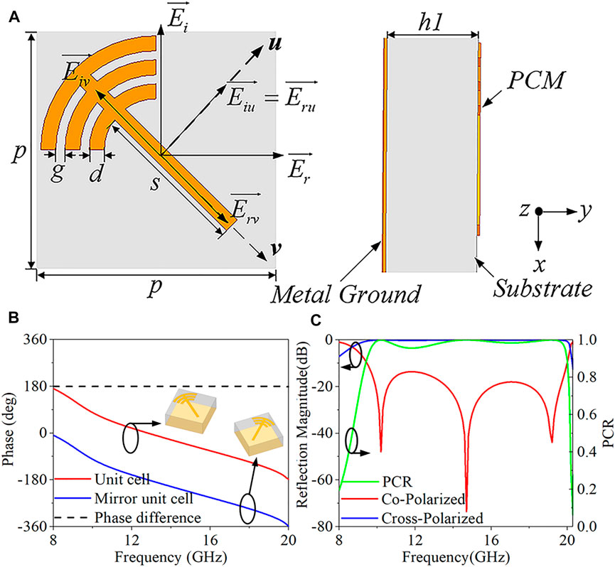
FIGURE 1. (A) Top view and side view of a typical unit cell. (B) The reflection phase of the unit cell and its mirror. (C) Co- and cross-polarized reflection coefficients and PCR of the proposed meta-atom.
In Figure 1A, to investigate the PC response of the proposed unit cell, the electric field
where m and n are the row and column numbers in the CPCM, respectively. p is the element periodicity.
Co-polarized and cross-polarized reflection coefficients with x-polarized incident waves are illustrated in Figure 1C. It can be seen that the operating band (where the co-polarization reflection coefficient is less than –10 dB) of the meta-atom is from 9.46 to 20.01 GHz. The polarization conversion ratio (PCR) is used to describe electromagnetic polarization rotation and is defined as the ability to convert x- or y-polarized waves into cross-polarized waves that can be expressed as
where
Meta-Antenna Design
Figure 2 shows the geometry and design process of the CP patch meta-antenna. The entire size of the meta-antenna is 64 mm × 64 mm × 3.5 mm. As depicted in Figure 2A, the antenna is designed with double dielectric plates (F4B). The antenna is composed of a patch, ground, and the feeding network. The top patch and the bottom feeding network are connected via two holes. Below the metal ground, the feeding network consisting of a Wilkinson power divider and a 90° broadband phase shifter was mounted on the bottom substrate with a thickness of h1. The Wilkinson power divider can achieve equal power division and impedance by transforming between input and output ports. After the original input signal splits into two ways, they pass through the two paths of the 90° phase shifter to obtain a stable phase shifting. In this design, a pair of
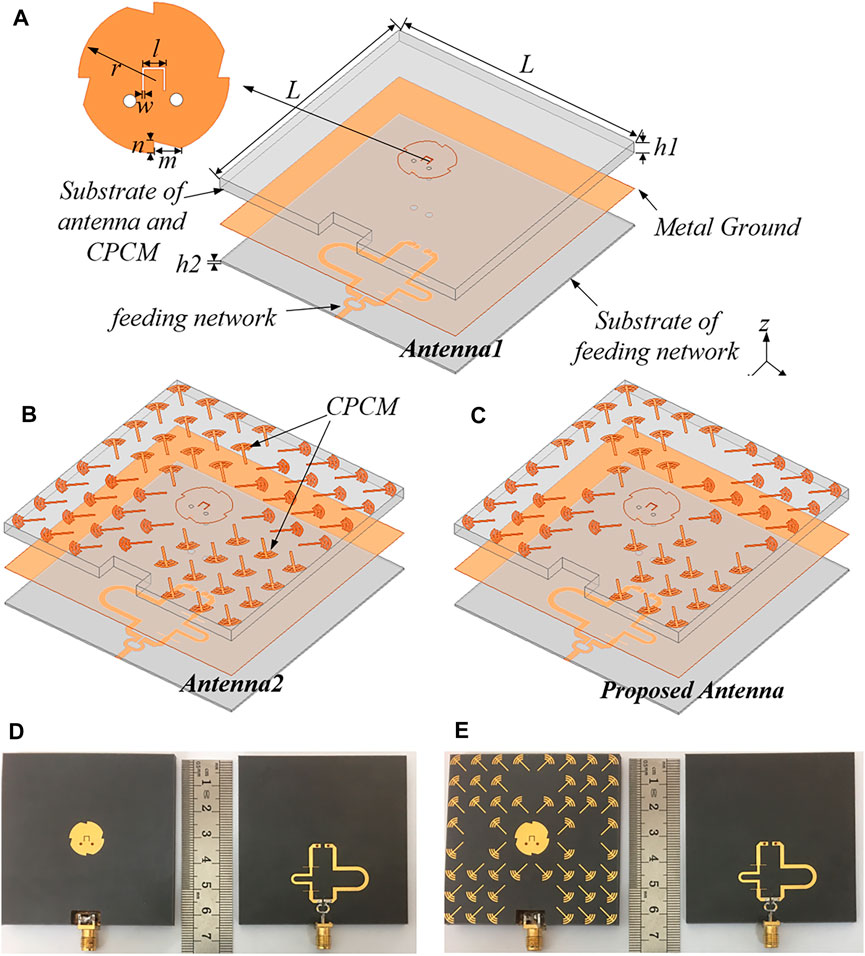
FIGURE 2. Design process of the proposed meta-antenna: (A) antenna1 and dimensional parameters of the antenna patch and substrate, (B) antenna2, and (C) the proposed meta-antenna. The corresponding photograph of the samples: (D) antenna1 and (E) the proposed meta-antenna.
The design process of the low-RCS meta-antenna is shown in Figures 2A–C. First, a CP slotted patch antenna was designed as the basic model shown in Figure 2A. The PC meta-atoms and their mirrors were arranged around the original antenna in a chessboard pattern to reduce the RCS of the whole structure, as shown in Figure 2B. In order to improve the radiation performance, some unit cells on the aperture were removed to relieve the coupling between the CPCM and the patch (Figure 2C). To demonstrate the performance of the proposed meta-antenna, the simulated and measured results were compared with those of the reference antenna without the CPCM. The antenna1 and the proposed meta-antenna were fabricated as shown in Figure 2 and Figure 2E, respectively. It should be emphasized that considering the good contact between the SMA connector and the metal ground, a 10 mm × 5 mm × 3 mm slot was cut at the edge of the substrate with a thickness of h2, which had a little effect on the radiation performance.
The simulated and measured reflection coefficients and axial ratios of antennas are shown in Figures 3A,B. The relative operation bandwidth of proposed meta-antenna and antenna1 were 26.48% (6.78–8.85 GHz) and 27.05% (6.84–8.98 GHz), respectively. The 3-dB axial ratio bandwidth of our design and antenna1 were 22.03% (7.27–9.07 GHz) and 19.39% (7.31–8.88 GHz). The realized gain is shown in Figure 3C, and the peak realized gain was 6.01 dB at 8.8 GHz. Furthermore, at 8.0–9.0 GHz, the realized gain of the proposed antenna increased by 1dB compared with that of the antenna1. The simulated and measured monostatic RCS are shown in Figure 3D. Compared with the reference antenna1, the proposed meta-antenna can achieve RCS reduction over 5 dB ranging from 8.5 to 21.5 GHz, which covers the working bandwidth of the proposed antenna. The peak RCS reduction at 19.4 GHz was 34.3 dB.
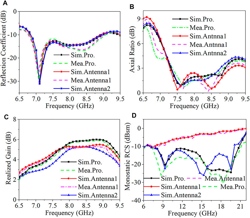
FIGURE 3. Simulated and measured reflection coefficients (A), axial ratio (B), realized gain (C), and monostatic RCS for the x-polarized incidence (D).
Referring to the results of antenna2 in Figures 3A–D, it is shown that placing a complete CPCM around an antenna has little influence on the return loss and axial ratio, but the gain of the antenna decreases by 1 dB at 7–7.75 GHz and 8.85–9.15 GHz without a CPCM because an inverting electric field is excited by several meta-atoms. The phase distribution of antenna2 at 7.5 and 8 GHz is shown in Figure 4A and Figure 4B, respectively. Therefore, to improve the realized gain of the meta-antenna, eight unit cells that are located at
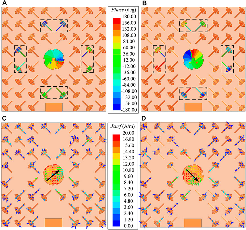
FIGURE 4. Phase distribution of antenna2 at 7.5 GHz (A) and 8 GHz (B). Surface current vector distribution of the proposed meta-antenna in the radiation case at 8 GHz: (C) phase = 0° and (D) phase = 90°.
The LHCP and right-hand circularly polarized (RHCP) radiation patterns of the proposed meta-antenna and the reference antenna at 8 GHz are shown in Figure 5. It can be seen that the main polarization is LHCP, which is consistent with the current vector distribution in Figure 4. The measured cross-polarization levels in both xoz-plane and yoz-plane were about 20 dB lower than co-polarizations. Moreover, the front-to-back ratios remained better than 20 dB at 8 GHz.
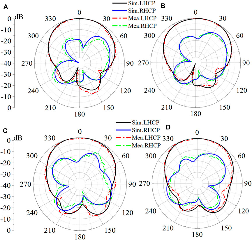
FIGURE 5. Simulated and measured 2D radiation patterns of the proposed meta-antenna at 8 GHz ((A) for xoz-plane; (C) for yoz-plane) and antenna1 ((B) for xoz-plane; (D) for yoz-plane).
In comparison, the performance of the proposed meta-antenna approached that of the antenna1, and the measured data are in good agreement with the simulation results. Some little differences are mainly due to the following reasons: I) machining and fabrication errors, II) interference of measurement environment and instrument settings, and III) the SMA and cable loss. In summary, the comparison of the above results shows that the CPCM causes little degradation in antenna radiation performance.
Conclusion
A CP slotted patch meta-antenna is presented in this article for reducing the backward RCS with the help of the predesigned CPCM. The measured results show that the proposed meta-antenna has an operating bandwidth of 6.79–9.06 GHz and 3-dB axial ratio bandwidth of 7.35–8.85 GHz, and the measured RCS reduction of more than 9 dB was achieved from 8.3 to 21.1 GHz without disturbing the radiation performance. Our design reached a good balance between the radiation feature and broadband stealth performance, and shows great prospects in practical applications.
Data Availability Statement
The original contributions presented in the study are included in the article/Supplementary Material, further inquiries can be directed to the corresponding authors.
Author Contributions
All authors listed have made a substantial, direct, and intellectual contribution to the work and approved it for publication.
Funding
This work was supported by the National Natural Science Foundation of China (Nos 62101394, 61722106, 62001338, and 61731010), the Fundamental Research Funds for the Central Universities (WUT: 2021IVA064 and 2021IVB029), and the Foundation from the Guangxi Key Laboratory of Optoelectronic Information Processing (GD21203).
Conflict of Interest
The authors declare that the research was conducted in the absence of any commercial or financial relationships that could be construed as a potential conflict of interest.
Publisher’s Note
All claims expressed in this article are solely those of the authors and do not necessarily represent those of their affiliated organizations, or those of the publisher, the editors, and the reviewers. Any product that may be evaluated in this article, or claim that may be made by its manufacturer, is not guaranteed or endorsed by the publisher.
References
1. Liu T, Cao X, Gao J, Zheng Q, Li W, Yang H. RCS Reduction of Waveguide Slot Antenna with Metamaterial Absorber. IEEE Trans Antennas Propagat (2013) 61(3):1479–84. doi:10.1109/TAP.2012.2231922
2. Liu Y, Zhao X. Perfect Absorber Metamaterial for Designing Low-RCS Patch Antenna. Antennas Wirel Propag Lett (2014) 13:1473–6. doi:10.1109/LAWP.2014.2341299
3. Wang W-T, Gong S-X, Wang X, Yuan H-W, Ling J, Wan T-T. RCS Reduction of Array Antenna by Using Bandstop FSS Reflector. J Electromagn Waves Appl (2009) 23(11):1505–14. doi:10.1163/156939309789476473
4. Genovesi S, Costa F, Monorchio A. Low-Profile Array with Reduced Radar Cross Section by Using Hybrid Frequency Selective Surfaces. IEEE Trans Antennas Propagat (2012) 60(5):2327–35. doi:10.1109/TAP.2012.2189701
5. Han Y, Zhu L, Bo Y, Che W, Li B. Novel Low-RCS Circularly Polarized Antenna Arrays via Frequency-Selective Absorber. IEEE Trans Antennas Propagat (2020) 68(1):287–96. doi:10.1109/TAP.2019.2939845
6. You-Quan Li Y, Hui Zhang H, Yun-Qi Fu Y, Nai-Chang Yuan N. RCS Reduction of Ridged Waveguide Slot Antenna Array Using EBG Radar Absorbing Material. Antennas Wirel Propag Lett (2008) 7:473–6. doi:10.1109/LAWP.2008.2001548
7. Pan W, Huang C, Chen P, Ma X, Hu C, Luo X. A Low-RCS and High-Gain Partially Reflecting Surface Antenna. IEEE Trans Antennas Propagat (2014) 62(2):945–9. doi:10.1109/TAP.2013.2291008
8. Zhang C, Long C, Yin S, Song RG, Zhang BH, Zhang JW, et al. Graphene-Based Anisotropic Polarization Meta-Filter. Mater Des (2021) 206:109768. doi:10.1016/j.matdes.2021.109768
9. Zhang C, Yin S, Long C, Dong BW, He D, Cheng Q. Hybrid Metamaterial Absorber for Ultra-low and Dual-Broadband Absorption. Opt Express (2021) 29(9):14078–86. doi:10.1364/OE.423245
10. Zhang C, Cheng Q, Yang J, Zhao J, Cui TJ. Broadband Metamaterial for Optical Transparency and Microwave Absorption. Appl Phys Lett (2017) 110(14):143511. doi:10.1063/1.4979543
11. Liu Y, Li K, Jia Y, Hao Y, Gong S, Guo YJ. Wideband RCS Reduction of a Slot Array Antenna Using Polarization Conversion Metasurfaces. IEEE Trans Antennas Propagat (2016) 64(1):326–31. doi:10.1109/TAP.2015.2497352
12. Liu Z, Liu S, Bornemann J, Zhao X, Kong X, Huang Z, et al. A Low-RCS, High-GBP Fabry-Perot Antenna with Embedded Chessboard Polarization Conversion Metasurface. IEEE Access (2020) 8:80183–94. doi:10.1109/ACCESS.2020.2990602
13. Pandit S, Mohan A, Ray P. Low-RCS Low-Profile Four-Element MIMO Antenna Using Polarization Conversion Metasurface. Antennas Wirel Propag Lett (2020) 19(2):2102–6. doi:10.1109/LAWP.2020.3023454
14. Li K, Liu Y, Jia Y, Guo YJ. A Circularly Polarized High-Gain Antenna with Low RCS over a Wideband Using Chessboard Polarization Conversion Metasurfaces. IEEE Trans Antennas Propagat (2017) 65(8):4288–92. doi:10.1109/TAP.2017.2710231
15. Zhang W, Liu Y, Jia Y. Circularly Polarized Antenna Array with Low RCS Using Metasurface-Inspired Antenna Units. Antennas Wirel Propag Lett (2019) 18(7):1453–7. doi:10.1109/LAWP.2019.2919716
16. Xie B, Tang K, Cheng H, Liu Z, Chen S, Tian J. Coding Acoustic Metasurfaces. Adv Mater (2017) 29(6):1603507. doi:10.1002/adma.201603507
Keywords: low profile, circularly polarized, broadband, radar cross-section reduction, meta-antenna
Citation: Zhou H, Wang Y, Liu C and Zhang C (2022) A Broadband Low-RCS Circularly Polarized Meta-Antenna. Front. Phys. 10:857960. doi: 10.3389/fphy.2022.857960
Received: 19 January 2022; Accepted: 27 January 2022;
Published: 25 February 2022.
Edited by:
Zhen Liao, Hangzhou Dianzi University, ChinaReviewed by:
Hai Lin, Central China Normal University, ChinaQiye Wen, University of Electronic Science and Technology of China, China
Copyright © 2022 Zhou, Wang, Liu and Zhang. This is an open-access article distributed under the terms of the Creative Commons Attribution License (CC BY). The use, distribution or reproduction in other forums is permitted, provided the original author(s) and the copyright owner(s) are credited and that the original publication in this journal is cited, in accordance with accepted academic practice. No use, distribution or reproduction is permitted which does not comply with these terms.
*Correspondence: Chengguo Liu, liucg@whut.edu.cn; Cheng Zhang, czhang2020@whut.edu.cn
 Hongkun Zhou