 Yuchao Wang
 Yangkun Song
 Cheng Zhang
- Hubei Engineering Research Center of RF-Microwave Technology and Application, School of Science, Wuhan University of Technology, Wuhan, China
In this paper, an output power reconfigurable rectenna array is proposed for the first time to harvest RF energy. The proposed rectenna array can be used to capture abundant RF energy with high conversion efficiency in a wide range of input power levels and load impedance at 1.88, 2.35, 3.5, and 4.9 GHz simultaneously. The output DC power of the proposed rectenna array can be changed exponentially by altering the on-off state of the switches located between the antenna and the rectifier. The measured result shows that the output power is linearly related to the number of opened switches. Therefore, the proposed rectenna array can be flexibly applied to battery-free or low-power-requiring devices according to their different power needs.
Introduction
To realize the interconnection of all things, wireless sensing networks are widely applied in our daily lives. Conventional batteries to power basic sensors are very inconvenient, and improper disposal of batteries can pollute the environment [1, 2]. The prompt development of wireless communication technology paves a new way to address these problems by utilizing a contactless charge strategy [3–5]. As the RF energy around us increases sharply, which is an abundant power source for electronic devices, the rectenna rises in response to this condition to gather RF energy.
Rectennas, as one of the key devices for harvesting RF energy, have experienced long-term development, and much effort has been made to enhance the overall RF-DC conversion efficiency and output DC power. Considering the above two aims, many rectennas with the characteristics of high efficiency [6, 7], broadband [8–10], multiband [11–13], or multiport [14, 15] have been extensively investigated by researchers in recent decades, driving the improvement of wireless energy usage. For example, a high-efficiency rectenna was proposed in Ref. [16] by directly matching the receiving antenna conjugately with a rectifier, and the efficiency could achieve 83% at 2.45 GHz when the input power level was 0 dBm. Furthermore, a compact and low-profile rectenna was proposed in Ref. [17], which strategically combines 12 single Vivaldi slot rectenna elements. The measured output DC power of the rectenna array could reach 65 µW in a real ambient environment outdoors.
From the abovementioned discussion, it is evident that with the development of energy harvesting technology, existing rectennas can meet the requirements of most daily applications, but once fabricated, their performance is fixed. Thus, without considering the discrepancy of the ambient power density, traditional rectennas lacking reconfigurability can supply specific devices, confining their practical application. Because the rated power and voltage of different devices are distinct, how to achieve the dynamic control of the output DC power according to the demands of the electrics must be solved.
To address the above problems, in this paper, a DC power reconfigurable 4 × 4 rectenna array is proposed by controlling the operating status of a single rectenna with the help of RF switches that are located between the antennas and rectifiers. The rectifier array is designed to operate at four frequency bands to harvest abundant RF energy, and the conversion efficiency of the proposed rectifier can achieve 53, 52, 49, and 45% at 1.88, 2.35, 3.5, and 4.9 GHz, respectively, when the input power level is −10 dBm. The receiving antenna is composed of four monopole antennas and an AMC structure to increase the gain of the antenna. To our knowledge, the proposed rectenna array is the first design to reconfigure the output power as desired and provides a new strategy for dynamic power supplements of different applications.
Rectifier Array Design
A rectifier array composed of four single shunt diode rectifiers is proposed in this section to realize high efficiency at four different working bands. We first designed a four-band rectifier and then arrayed it (four rectifiers) to harvest more RF energy and flexibly control the output power levels. The detailed design process is described as follows.
The topological structure of the proposed four-band rectifier is shown in Figure 1A. It consists of two single shunt diode rectifier branches in parallel to obtain four operating bands. Each rectifier branch comprises a diode, DC-pass filter, and matching network. To improve the RF-DC conversion at a low input level, the Schokkty diode SMS7630 is chosen as the rectifier diode due to its low-loss property within a broad power range (from −20 to 0 dBm).
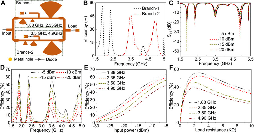
FIGURE 1. (A) The topology of the proposed rectifier. (B) Simulated RF-DC conversion efficiency of the three branches at the input power level of −10 dBm. (C,D) Simulated reflection coefficient and RF-DC conversion efficiency of the proposed rectifier at different input power levels for a load resistance of 2000 Ω. (E) Simulated RF-DC conversion efficiency of the proposed rectifier versus input power level for a load resistance of 2000 Ω. (F) Simulated RF-DC conversion efficiency of the proposed rectifier versus load resistance at an input power of −10 dBm.
In addition, the DC-pass filter is designed by connecting a transmission line and a radius branch in series to prevent RF energy from passing through the load. To develop a four-band rectifier, each rectifier branch is designed to operate at two frequency bands by mainly designing the matching network and the DC-pass filter. A Π-type matching network is optimized to match the single shunt diode rectifier to 50 Ω. The ultimate structure of the proposed four-band rectifier is shown in Figure 1A. Furthermore, to study the contribution of the two branches, the simulated RF-DC conversion efficiency of the two branches at an input power level of −10 dBm is presented in Figure 1B. It is easy to find that branch-1 can rectify the RF energy at 1.88 and 2.35 GHz, and the other branch (branch-2) is able to operate at 3.5 and 4.9 GHz. Moreover, almost the entire RF power can be converted to DC power by the corresponding rectifier branches.
The simulated S11 and conversion efficiency of the proposed rectifier versus frequency are also shown in Figures 1C,D at four different input power levels (−5, −10, −15, and −20 dBm). The rectifier maintains robust efficiency as the input power level changes. In addition, the four designed operating frequencies hardly change with different input power levels. Because the input impedance of the diode changes with the input power level, the effect of the input power level on the conversion efficiency was studied, as shown in Figure 1E. The efficiency increases as the input power increases from −30 to −5 dBm, making our design suitable for a wide range of environmental power levels. Next, the effect of the load resistance on the efficiency was also studied when the input power was −10 dBm (Figure 1F), and the optimal load resistance of approximately 2000 Ω was determined by comprehensively considering the efficiency of the four working bands. In addition, our design is insensitive to the load resistance, and stable efficiency can be maintained even when the load resistance dramatically changes (1,000 Ω–10,000 Ω).
To date, a single four-band rectifier (SFR) has been achieved by adopting a dual-branch circuit. In the following, the four uniform SFRs are connected in parallel to form a rectifier array, as shown in Figure 2A. To study the isolation between different input ports, S21, S31, and S41 are shown in Figure 2B. It is obvious that port 1 has great isolation with port 2, port 3, and port 4 since the other three SFRs hardly affect SFR-1 due to the elaborate matching network and DC-pass filter. Of course, the isolation performance of any two ports is the same as above since the four ports are symmetrical.
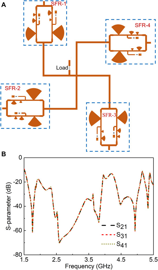
FIGURE 2. (A) The topology of the proposed rectifier array. (B) The simulated S21, S31, S41 of the rectifier array at an input power of −10 dBm.
To verify our design, a prototype size of 196 mm × 196 mm was printed on a low-cost F4B substrate with a relative permittivity of 2.2, loss tangent of 0.0011, and thickness of 0.787 mm (Figure 3A). The reflection coefficient of the rectifier was measured with a vector network analyzer (VNA, Agilent E5072A). The measured S11 at four different input power levels is shown in Figure 3A. Although a slight discrepancy can be observed for S11, the measured results (Figure 3A) are still consistent with the simulated results (Figure 1C), including the four predesigned frequency bands. Next, the conversion efficiency was measured as a function of the input power level at four operating frequency bands, as shown in Figure 3B. The measured result shows that the conversion efficiency achieved 47.8, 44.6, 45.2, and 38.1% at 1.88, 2.35, 3.5, and 4.9 GHz, respectively, when the input power was −10 dBm. Consistent with the simulation results, the conversion efficiency improved as the input power level increased due to diode losses increasing more slowly than the input power. However, the measured efficiency was lower than the simulated efficiency due to the unknown parasitic behavior of the diode. In addition, the S21, S31, and S41 of the rectifier array were also measured to study the isolation of the different ports. The rectifier array has great isolation at the four operating frequency bands. Although there are some deviations between the measured and simulated results, the measured results also verify the excellent performance of the designed rectifier at low input power levels.
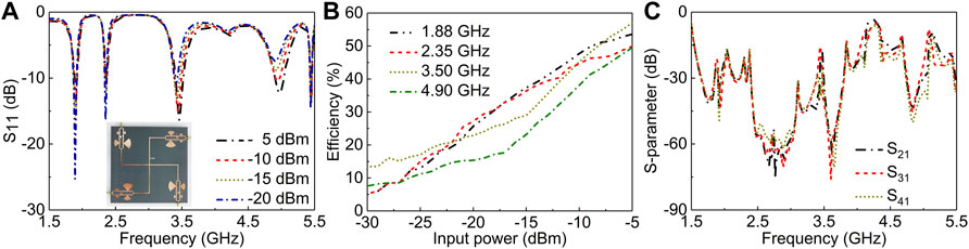
FIGURE 3. (A) Measured reflection coefficient of the proposed rectifier at different input power levels for a load resistance of 2000 Ω. (B) Measured RF-DC conversion efficiency of the proposed rectifier versus input power level a for a load resistance of 2000 Ω. (C) Measured S21, S31, S41 of the rectifier array at an input power of −10 dBm.
Broadband High Gain Antenna Array Design
A broadband monopole antenna array integrated with an artificial magnetic conductor (AMC) is proposed as the receiving antenna of the rectenna array due to its high gain characteristic. In addition, the reflecting ground plane can be integrated with the rectifier array to decrease the size of the rectenna array. The proposed broadband high gain antenna array was made on an F4b substrate with a relative permittivity of 2.2. The substrate thickness of the monopole antenna array was 0.787 mm and that of the AMC array was 0.508 mm. The distance between the antenna and the AMC was designed as 5 mm by comprehensively considering the profile and the effect of the AMC on the input impedance of the antenna. To extend the operating band (where the reflection phase ranges from −90° to +90°) of the AMC, the distance between the AMC and reflecting ground plane was designed as 20 mm.
The receiving antenna consists of four independent high gain antennas (HGA). Each HGA was designed by combining the monopole antenna with AMC to achieve high gain and broadband performance. The size of the monopole antenna is dependent on the operating frequency. To reduce the omnidirectional radiation of the monopole, an AMC was placed under the monopole antenna to increase the gain of the receiving antenna. The AMC is consisted of 24 × 24 square ring cells, and the dimension of the AMC cells is shown in Figure 4A. This design improves the radiation performance (S11), and the corresponding impedance bandwidth can be extended to 1.79∼5.31 GHz as shown in Figure 4B. Next, similar to the rectifier array design, the isolation feature of the antenna array was also studied, as shown in Figure 4C. It is obvious that the isolation performance between port 1 and port 2 (port 4) is excellent since the polarization of the two antennas is vertical. In addition, S31, denoting the isolation between port 1 and port 3, is also less than −15 dB at the operating band, showing little cross-talk between ports. Similar characteristics of other ports can be drawn since the locations of the four monopoles are rotationally symmetric.
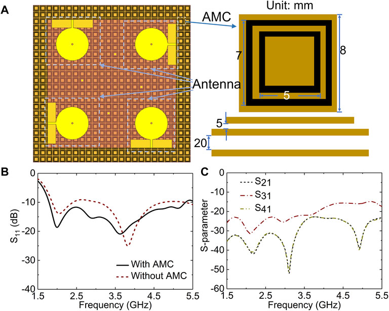
FIGURE 4. (A) Geometry of the proposed antenna array. (B) Simulated reflection coefficient of the antenna with and without AMC structure. (C) Simulated S21, S31, S41 of the antenna array.
For evaluation, the proposed optimal antenna array was printed on a 0.787-mm-thick F4B substrate, as shown in Figure 5B, and the measured S11, S21, S31, and S41 of the fabricated antenna array are illustrated in Figure 5A. The measured relative impedance bandwidth (|S11|<−10 dB) of the antenna was 101.1% (1.74–5.3 GHz), and the center frequency was approximately 3.52 GHz. The measured S21, S31, and S41 show that the four antennas have great isolation. The simulated and measured realized gains of the antenna are also shown in Figure 5B. The measured gain was approximately 7∼9.5 dBi over the entire operating band. The simulated and measured 2-D radiation patterns of the proposed antenna array at 2.35 and 3.5 GHz are given in Figure 5C. The measured results agree well with the simulated results.
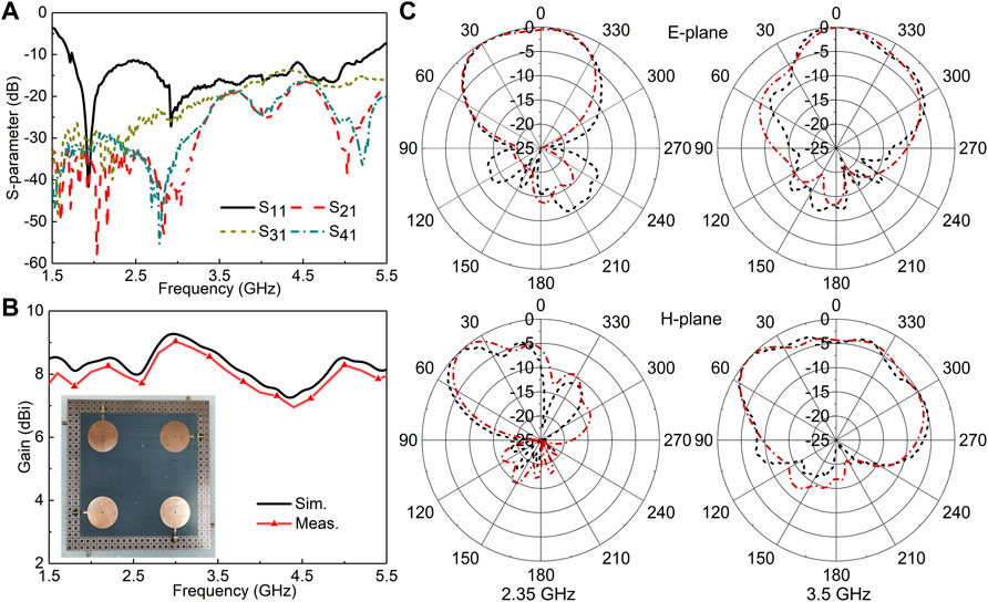
FIGURE 5. Measured S-parameter (A), gain (B) and radiation pattern (C).
Output Power Reconfigurable Rectenna Array
Ultimately, the rectifier array is located under the AMC, and the ground plane of the rectifier array was designed as the reflecting plane of the AMC to reduce the overall size. A photograph of the proposed power-reconfigurable rectenna array is shown in Figures 6A,B. Each HGA is connected to SFR by an RF switch to compose the dynamic rectenna array. The on-off state of the RF switch can be tuned by adding a 5 V bias voltage or not, which is provided by a single chip microcomputer, as shown in Figure 6C. The measured S21 of the RF switch is also shown in Figure 6D. The status of the RF switch can effectively affect the transmissive energy level, and therefore, the input energy to the rectifier is decided by changing the number of opened switches, resulting in the dynamic control of the output DC power.
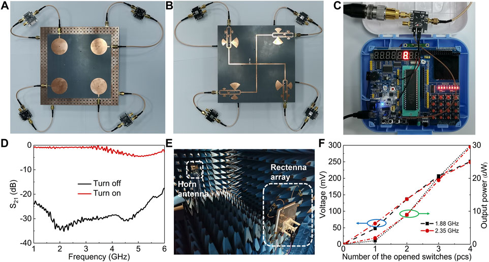
FIGURE 6. (A,B) Photograph of the rectenna array. (C) The photograph of the single chip microcomputer and RF switch. (D) The measured S21 of the switch. (E) Measurement setup inside an anechoic chamber. (F) Measured voltage and out power of the rectenna array versus the number of the opened switches.
To verify our design, the power reconfigurable rectenna array is measured in a microwave anechoic chamber, where the horn antenna connected with an RF signal generator is used as a transmitting antenna, and our design is adopted to receive RF energy, as shown in Figure 6E. The distance between the horn antenna and rectenna was taken as 2.7 m. Next, the output voltage and DC power across the load resistance were measured at 1.88 and 2.35 GHz with the number of opened switches, as shown in Figure 6F. The output voltage and output power increase with an increasing number of opened switches at two frequency bands. That is, in practice, different numbers of RF switches can be turned on according to the power required by the load.
Conclusion
In this paper, a reconfigurable rectenna array was proposed to realize the dynamic manipulation of the output DC power. The rectifier array and antenna array prototypes were constructed and measured to demonstrate the performance. The measured result shows that when the input RF energy is fixed, the output DC power can be successfully divided into four different levels by controlling the on-off state of the external RF switches. Our design shows great potential in driving low-power electronics since it can adjust its output voltage or output power according to the needs of applications.
Data Availability Statement
The original contributions presented in the study are included in the article/Supplementary Material, further inquiries can be directed to the corresponding authors.
Author Contributions
All authors listed have made a substantial, direct, and intellectual contribution to the work and approved it for publication.
Funding
This work was supported by the National Natural Science Foundation of China (62101394, 61722106, 62001338, and 61731010), the Fundamental Research Funds for the Central Universities (WUT: 2021IVA064, and 2021IVB029), and the Foundation from the Guangxi Key Laboratory of Optoelectronic Information Processing (GD21203).
Conflict of Interest
The authors declare that the research was conducted in the absence of any commercial or financial relationships that could be construed as a potential conflict of interest.
Publisher’s Note
All claims expressed in this article are solely those of the authors and do not necessarily represent those of their affiliated organizations, or those of the publisher, the editors and the reviewers. Any product that may be evaluated in this article, or claim that may be made by its manufacturer, is not guaranteed or endorsed by the publisher.
References
1. Song C, Huang Y, Zhou J, Carter P, Yuan S, Xu Q, et al. Matching Network Elimination in Broadband Rectennas for High-Efficiency Wireless Power Transfer and Energy Harvesting. IEEE Trans Ind Electron (2017) 64(5):3950–61. doi:10.1109/tie.2016.2645505
2. Varasteh M, Rassouli B, Clerckx B. On Capacity-Achieving Distributions for Complex AWGN Channels under Nonlinear Power Constraints and Their Applications to SWIPT. IEEE Trans Inform Theor (2020) 66(10):6488–508. doi:10.1109/tit.2020.2998464
3. Zhang C, Long C, Yin S, Song RG, Zhang BH, Zhang JW, et al. Graphene-based Anisotropic Polarization Meta-Filter. Mater Des (2021) 206:109768. doi:10.1016/j.matdes.2021.109768
4. Zhang C, Yin S, Long C, Dong BW, He D, Cheng Q. Hybrid Metamaterial Absorber for Ultra-low and Dual-Broadband Absorption. Opt Express (2021) 29(9):14078–86. doi:10.1364/OE.423245
5. Zhang C, Cheng Q, Yang J, Zhao J, Cui TJ. Broadband Metamaterial for Optical Transparency and Microwave Absorption. Appl Phys Lett (2017) 110(14):143511. doi:10.1063/1.4979543
6. Nie M-J, Yang X-X, Tan G-N, Han B. A Compact 2.45-GHz Broadband Rectenna Using Grounded Coplanar Waveguide. Antennas Wirel Propag Lett (2015) 14:986–9. doi:10.1109/lawp.2015.2388789
7. Li X, Yang L, Huang L. Novel Design of 2.45-GHz Rectenna Element and Array for Wireless Power Transmission. IEEE Access (2019) 7:28356–62. doi:10.1109/access.2019.2900329
8. Mansour MM, Kanaya H. High-Efficient Broadband CPW RF Rectifier for Wireless Energy Harvesting. IEEE Microw Wireless Compon Lett (2019) 29(4):288–90. doi:10.1109/lmwc.2019.2902461
9. Liu W, Huang K, Wang T, Zhang Z, Hou J. A Broadband High-Efficiency RF Rectifier for Ambient RF Energy Harvesting. IEEE Microw Wireless Compon Lett (2020) 30(12):1185–8. doi:10.1109/lmwc.2020.3028607
10. He Z, Liu C. A Compact High-Efficiency Broadband Rectifier with a Wide Dynamic Range of Input Power for Energy Harvesting. IEEE Microw Wireless Compon Lett (2020) 30(4):433–6. doi:10.1109/lmwc.2020.2979711
11. Singh N, Kanaujia BK, Tariq Beg M, Mainuddin S, Kumar S. A Triple Band Circularly Polarized Rectenna for RF Energy Harvesting. Electromagnetics (2019) 39(7):481–90. doi:10.1080/02726343.2019.1658164
12. Keshavarz R, Shariati N. Highly Sensitive and Compact Quad-Band Ambient RF Energy Harvester. IEEE Trans Ind Electron (2022) 69:3609–21. doi:10.1109/tie.2021.3075888
13. Song C, Huang Y, Carter P, Zhou J, Yuan S, Xu Q, et al. A Novel Six-Band Dual CP Rectenna Using Improved Impedance Matching Technique for Ambient RF Energy Harvesting. IEEE Trans Antennas Propagat (2016) 64(7):3160–71. doi:10.1109/tap.2016.2565697
14. Shen S, Chiu C-Y, Murch RD. A Dual-Port Triple-Band L-Probe Microstrip Patch Rectenna for Ambient RF Energy Harvesting. Antennas Wirel Propag Lett (2017) 16:3071–4. doi:10.1109/lawp.2017.2761397
15. Shen S, Zhang Y, Chiu C-Y, Murch R. An Ambient RF Energy Harvesting System where the Number of Antenna Ports Is Dependent on Frequency. IEEE Trans Microwave Theor Techn. (2019) 67(9):3821–32. doi:10.1109/tmtt.2019.2906598
16. Sun H, Guo Y, He M, Zhong Z. Design of a High-Efficiency 2.45-GHz Rectenna for Low-Input-Power Energy Harvesting. Antennas Wirel Propag Lett (2012) 11:929–32. doi:10.1109/lawp.2012.2212232
Keywords: four-band rectifier, high gain antenna, reconfigurabale rectifier array, RF energy harvesting, output DC power control
Citation: Wang Y, Song Y, Zhang B, Chen S, Chen Q and Zhang C (2022) A High-Efficiency and Reconfigurable Rectenna Array for Dynamic Output DC Power Control. Front. Phys. 10:866656. doi: 10.3389/fphy.2022.866656
Received: 31 January 2022; Accepted: 14 February 2022;
Published: 28 February 2022.
Edited by:
Zhen Liao, Hangzhou Dianzi University, ChinaCopyright © 2022 Wang, Song, Zhang, Chen, Chen and Zhang. This is an open-access article distributed under the terms of the Creative Commons Attribution License (CC BY). The use, distribution or reproduction in other forums is permitted, provided the original author(s) and the copyright owner(s) are credited and that the original publication in this journal is cited, in accordance with accepted academic practice. No use, distribution or reproduction is permitted which does not comply with these terms.
*Correspondence: Qiang Chen, cWlhbmdjaGVuQHdodXQuZWR1LmNu; Cheng Zhang, Y3poYW5nMjAyMEB3aHV0LmVkdS5jbg==