95% of researchers rate our articles as excellent or good
Learn more about the work of our research integrity team to safeguard the quality of each article we publish.
Find out more
ORIGINAL RESEARCH article
Front. Phys. , 05 April 2022
Sec. Optics and Photonics
Volume 10 - 2022 | https://doi.org/10.3389/fphy.2022.850770
This article is part of the Research Topic Application of Terahertz Frequency in Substance Detection and Recognition View all 9 articles
The polarization measurement of terahertz (THz) waves is indispensable in THz time-domain spectroscopy (THz-TDS) applications to detect material properties. The rapid development of accurate THz wave polarization-sensitive detectors will greatly promote THz-TDS applications. A new type of photoconductive antenna array detector is proposed in this paper. The antenna is composed of two vertical 1*2 arrays, which respectively detect the orthogonal component of the terahertz pulse in any direction, while quickly and accurately detecting the polarized THz waves. Rotating the detector to measure the THz electric field at different angles shows the reliability of the detector for THz wave polarization measurement. Its polarization detection accuracy is 0.2°. At the same time, we use the response matrix to analyze the symmetry of the antenna array.
The THz time-domain spectroscopy (THz-TDS) system can be used to detect the spectral characteristics of materials in the range of hundreds of GHz to several THz, and has been widely used in material science [1], chemistry [2], biomolecules [3–5], nerve cells [6], security inspection [7], and other fields. Usually, we use the THz-TDS system to obtain two crucial information about samples: refractive index and absorption coefficient [8]. However, for chiral materials such as birefringent or optically active materials, the polarization measurement of the THz electric field is crucial for the accurate acquisition of the characteristic parameters of the sample. Therefore, a detector capable of simultaneously measuring the polarization state of the THz electric field and the spectral information of the sample is necessary. Since Auston proposed photoconductive dipole antennas [9], dipole antennas have been rapidly developed as THz transmitters and receivers in THz-TDS systems. In the polarization measurement of THz waves using dipole antennas, the photoconductive dipole antennas can only detect the THz electric field amplitude in one direction at a time, that is, the projection of THz electric field amplitude on the direction of dipole antenna electrodes. In fact, the polarization direction of the THz electric field is determined by the direction of the electrostatic field of the transmitting antenna. Similarly, the direction of the antenna electrode also determines the magnitude of the photocurrent caused by polarized THz electric field received by the detection antenna. Among many photoconductive antenna detectors, the geometric structure of the three-contact electrode [10] and the four-contact electrode [11] have proved their ability to detect the polarization direction of THz electric field, however, its effective area for receiving the THz wave is exceedingly small and cannot be expanded. The photoconductive antenna array detector of the interdigital electrode [12] can expand the effective area while measuring the polarization of the THz electric field; however, it still has the shortcoming of the traditional interdigital antenna array: the reverse current between adjacent antenna elements [13]. Therefore, the photoconductive antenna detector used for the THz electric field polarization measurement still needs to be improved in terms of the effective area, sensitivity, and detection efficiency.
In this paper, a THz polarization detector based on the photoconductive antenna array is designed to eliminate the reverse current between adjacent antenna elements and improve polarization detection sensitivity. By measuring the quadrature components of THz electric field by the detector at different angles, the dependence of the response matrix factor on the frequency is obtained, and the symmetry of the antenna array is analyzed. In addition, the effective area of the detector to receive THz waves is expandable, which is beneficial to improve the detector’s performance.
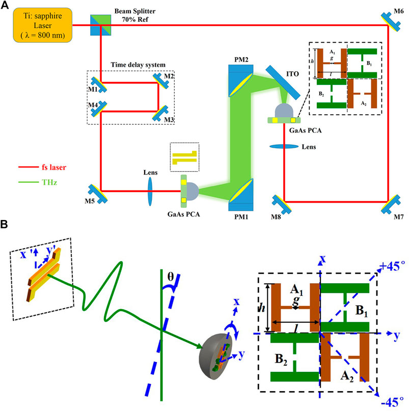
There have been many reports on the principle description of the photoconductive antenna for detecting THz waves [14, 15], and the preparation method of the photoconductive antenna designed in this paper has been reported [16], therefore, this part will not be described here. The THz-TDS system used in the experiments is shown in Figure 1A. The laser used in the experiment has a wavelength of 800 nm, a pulse width of 104 fs, and a repetition frequency of 80 MHz. A dipole emitting antenna with a gap of 150 μm is used, a bias voltage of 240 V is applied, and the electrode gap is vertical. The photoconductive antenna array detector designed in this paper is a four-antenna centrally symmetric layout, which is shown in the inset of Figure 1A. The adjacent antennas are arranged orthogonally to form a dual signal channel to obtain the orthogonal components of the THz electric field in any direction. The electrode directions of A1 and A2 are the same, so are B1 and B2. The A1A2 and B1B2 electrode directions are perpendicular to each other to form a dual signal channel. The photoconductive antenna element gap g = 50 μm, and h = l = 990 μm. The effective area of each antenna element receiving THz wave is 30 μm × 50 μm. The detector is integrated into a silicon lens with a diameter of 1 cm and fixed in a rotation stage, as shown in Figure 1B. In this paper, it is specified as follows: the coordinate system of the photoconductive antenna array detector is x - y; the emitting antenna coordinate system is x' - y', the direction of the electrostatic field of the emitting antenna is along the x' axis, and the two electrodes are in y' axis, the rotation axis of the photoconductive antenna array detector overlaps with the propagation direction of the THz wave.

FIGURE 1. (A) THz-TDS system and photoconductive antenna array detector structure for polarization detection and (B) Schematic diagram of antenna array detector’s rotation.
The response of the photoconductive antenna array detector to the orthogonal components of the THz electric field can be described by the response matrix [17],
where ω is the frequency of electromagnetic waves in the THz band, Ex’ (ω) and Ey′(ω) represent the spectral signal components of the incident THz electric field in the x′ and y′ directions, respectively. SA1A2(ω) and SB1B2(ω) are the signals after the Fourier transformation of the time-domain signals SA1A2(τ) and SB1B2(τ) that the photoconductive antenna array detector responds to. M(ω) is the response matrix of the photoconductive antenna array detector. The M(ω) can be described as:
Since the long axis and short axis of the THz electric field in the optical path system are constants, the orthogonal projection component of the long axis (short axis) on the photoconductive antenna array detector changes linearly, so the elements of one set of diagonal response matrices are zero. When the photoconductive antenna array detector rotates,
where θ is the angle between the x'-axis (or y'-axis) and the x-axis (or y-axis). A1A2 is initially placed vertically (θ = 0°), and E0x and E0y are the initial electric field components with constant values. For the convenience of discussion, the dependence on frequency ω is omitted. According to the detection data of the photoconductive antenna array detector at θ = +/-45°, the response matrix can be calculated as:
in which,
At the same time, the angle of the polarization direction of the THz electric field can be calculated:
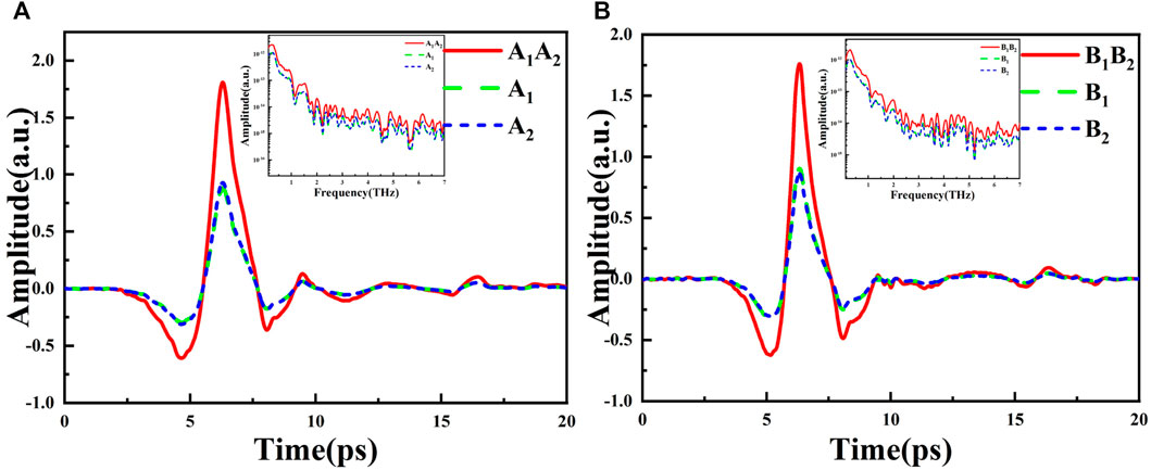
Before polarization measurement, we need to make sure that there is no reverse current between adjacent antenna elements, because the interference of reverse current will reduce the signal-to-noise ratio and measurement accuracy of polarization detection. According to the layout characteristics of the photoconductive antenna array detector, the experiments have tested the synthesis efficiency of the A1A2 and B1B2, as shown in Figure 2A,B. Taking A1A2 as an example, the algebra sum of the peak-to-peak amplitude of the THz signal received by them is used as the peak-to-peak amplitude of the reference signal, and the synthesis efficiency can be calculated according to the amplitude of the actual output signal of the array A1A2 and B1B2. The experimental results show that the synthesis efficiency of the array A1A2 is 98.1%, and that of B1B2 is 99.9%. In addition, the largest difference in signal amplitudes appears between A1 and B2, and the amplitude difference is only 2.98%, which shows that the THz and laser energy received by each antenna element gap can be considered to be the same. The signal amplitude data of the antenna elements and the array are shown in Table 1.

FIGURE 2. Photoconductive detection antenna array detector at θ = 45° (A) The amplitude synthesis effect of A1, A2 and (B) The amplitude synthesis effect of B1 and B2.
In order to preliminarily verify the expected operation of the detector, three cases of orthogonal polarizations were tested. Firstly, θ = 0°, A1 and A2 detect the horizontally polarized THz electric field, B1 and B2 detect the vertically polarized THz electric field. Secondly, θ = 45°, A1, A2, and B1, B2 detect the same magnitude projection components of the THz electric field in the x and y directions, respectively. Thirdly, θ = 90°, B1 and B2 detect the horizontally polarized THz electric field, A1 and A2 detect the vertically polarized THz electric field. The polarization-resolved time-domain trace are shown in Figure 3A–C. By rotating the detector, the antennas array detected the polarization state of the THz electric field as expected. The THz electric field in the figures show a certain degree of elliptical polarization. The reasons for this phenomenon can be explained as follows: firstly, the dipole photoconductive antenna emitter will generate a small quadrupole field; secondly, the low-f acquisition system make the linear polarization amplitude slightly elliptical [18, 19]; finally, the frequency-dependent cross polarization of the dipole radiation field [20].

FIGURE 3. THz time-domain signal of photoconductive antenna array detector at angles (A) θ = 0° (B) θ = 45° and (C) θ = 90°.
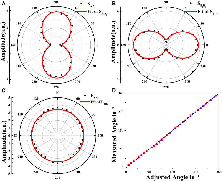
The polarization state of the THz pulse is constant during the rotation of the photoconductive antenna array detector. By rotating the photoconductive antenna array detector in the range of 360°, the peak-to-peak amplitude of the time-domain signal of antennas A1, A2, and B1, B2 distributed in the polar coordinates is shown in Figure 4A,B. Angle change step size is 10°, and the red curve is the sine curve fitted to the scatter diagram. The distribution law of the scattered points is consistent with the fitted curve and has good symmetry. The peak-to-peak amplitude of the signals at all angles have been taken as a positive value, the amplitude peak-to-peak value of A1A2 and B1B2 varies with angle are in accordance with Malus's Law. The signal amplitudes of the antennas in groups A1 and A2 are not zero at 0° and 180°, so are B1 and B2 at 90° and 270°, indicating that the THz pulse does have a certain degree of elliptic polarization. Since the total energy of the radiated THz pulse is constant and the amplitude of the THz electric field can be expressed as

FIGURE 4. (A) A1, A2, and (B) B1, B2 time-domain signal amplitude distribution in polar coordinates (C) THz pulse amplitude change, and (D) The error relationship between the experimentally measured THz direction angle and target angle.
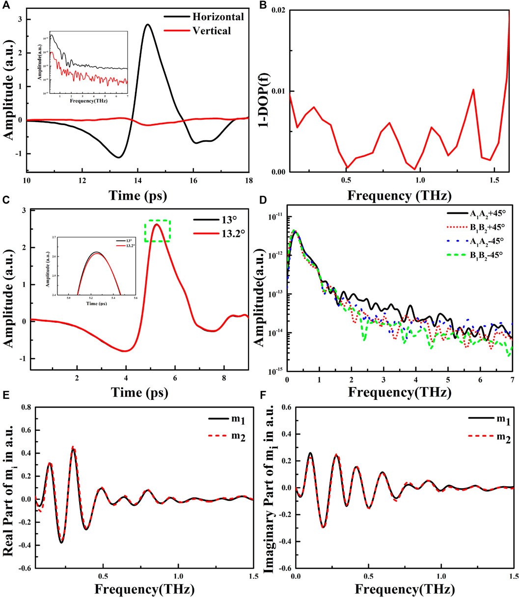
At θ = 0°, the frequency-dependent degree of polarization (DOP) is calculated. The two 1*2 antenna arrays detect the long-axis and short-axis components of the THz electric field respectively, as shown in Figure 5A. In order to characterize the polarization state of the THz electric field, we use DOP to describe the degree of linear polarization in terahertz:
Where

FIGURE 5. At θ = 0° (A) The horizontal and vertical THz electric field of the photoconductive antenna array detector and (B) Experimental measurement of DOP (C) Response accuracy of photoconductive antenna array to polarized THz electric field at θ = 13° (D) The frequency spectrum corresponding to the dual-channel signal of the photoconductive detection antenna array at θ = +/-45°; The relationship between the real part (E) and imaginary part (F) of the response matrix factors m1 and m2 with frequency.
At θ = 13°, we characterize the accuracy of the detector’s response to polarized terahertz electric fields. The rotation stage used in the experiment is PR50CC, and the minimum incremental motion is 0.02°. As shown in Figure 5C, where a local enlargement of the peak amplitude is shown in the green box. The detector has distinguishable signal amplitude changes at θ = 13° and θ = 13.2°, indicating that the detector’s detection accuracy of the polarized THz electric field is 0.2°.
At θ = +/-45°, the time domain signals of arrays A1A2 and B1B2 are Fourier transformed, as shown in Figure 5D, the spectral amplitudes of the two 1*2 arrays are not strictly equal. This is the actual working state of the antenna, which deviates from the ideal state. According to the spectrum, we can calculate the response matrix factors m1 and m2, and m1 ≠ m2, the deviation between m1 and m2 can be explained from the following aspects: 1) the signal-to-noise ratio will affect the accuracy of the matrix calculation; 2) the deviation between m1 and m2 is frequency dependent, as shown in Figure 5E,F, the amplitude difference between the real and imaginary parts of m1 and m2 gradually decreases with the increase of frequency, this is due to the effect of the lead wire on the electrode surface, and the influence of the lead wire on the surface of the antenna electrode is weaker at higher frequencies [11]; 3) the rotating frame of the detector is not accurate enough, resulting in a systematic error in the axial offset during the rotation of the frame. Therefore, the response matrix can be simplified as:
where l and k are both constant and complex value. Therefore, the expression of the detector for THz polarization measurement can be changed to:
It should be emphasized that the deviation between l and k is almost only in the low-frequency range, and l and k are almost equal in the range of 0.3–1.5 THz, therefore, the photoconductive antenna array detector has good symmetry, which is important for polarization detection of THz electric field.
This paper presents the design of a highly efficient photoconductive antenna array detector for THz electric field polarization detection. The detector consists of two perpendicular 1*2 arrays, which detect the horizontal and vertical components of the terahertz pulse respectively. The synthesis degree of two perpendicular 1*2 array are 98.1 and 99.9%. The detector has a dual signal channel, which can simultaneously obtain the amplitude and phase of the terahertz pulse electric field component received by two vertical 1*2 arrays, and give the direction of polarization. The measurement results at different angles are consistent with Malus’ law, which shows the reliability of the detector for polarization THz measurement. The polarization detection accuracy of this detector is 0.2°, and the spectrum DOP(f) is greater than 99% in the 0.1THz-1.5 THz spectrum range. At the same time, we also calculated the expression of the response matrix. The slight difference in the matrix factor indicates that the detector has good symmetry. The new terahertz detection antenna can measure the amplitude, phase and polarization state of the incident terahertz pulse at one time.
The original contributions presented in the study are included in the article/Supplementary Material, further inquiries can be directed to the corresponding author.
Academic thought and preparation of new detection antenna, WS; methodology, LH.; data curation, CF.L. and YP; writing—original draft preparation, ZQ.W.; writing—review and editing, W.S. All authors have read and agreed to the published version of the manuscript.
This research was funded by the National Key Research and Development Program of China (Grant No. 2017YFA0701005), Special Scientific Research Plan of Shaanxi Provincial Education Department, China (Grant No. 19JK0297).
The authors declare that the research was conducted in the absence of any commercial or financial relationships that could be construed as a potential conflict of interest.
All claims expressed in this article are solely those of the authors and do not necessarily represent those of their affiliated organizations, or those of the publisher, the editors and the reviewers. Any product that may be evaluated in this article, or claim that may be made by its manufacturer, is not guaranteed or endorsed by the publisher.
1. Hangyo M, Tani M, Nagashima T. Terahertz Time-Domain Spectroscopy of Solids: A Review. Int J Infrared Milli Waves (2005) 26(12):1661–90. doi:10.1007/s10762-005-0288-1
2. Fischer B, Hoffmann M, Helm H, Modjesch G, Jepsen PU. Chemical Recognition in Terahertz Time-Domain Spectroscopy and Imaging. Semicond Sci Technol (2005) 20(7):S246–S253. doi:10.1088/0268-1242/20/7/015
3. Falconer RJ, Markelz AG. Terahertz Spectroscopic Analysis of Peptides and Proteins. J Infrared Milli Terahz Waves (2012) 33(10):973–88. doi:10.1007/s10762-012-9915-9
4. Peng Y, Shi C, Zhu Y, Gu M, Zhuang S. Terahertz Spectroscopy in Biomedical Field: a Review on Signal-To-Noise Ratio Improvement. PhotoniX (2020) 1(1):1–18. doi:10.1186/s43074-020-00011-z
5. Shi W, Wang Y, Hou L, Ma C, Yang L, Dong C, et al. Detection of Living Cervical Cancer Cells by Transient Terahertz Spectroscopy. J Biophotonics (2021) 14(1):e202000237. doi:10.1002/jbio.202000237
6. Liu G, Chang C, Qiao Z, Wu K, Zhu Z, Cui G, et al. Myelin Sheath as a Dielectric Waveguide for Signal Propagation in the Mid-infrared to Terahertz Spectral Range. Adv Funct Mater (2019) 29(7):1807862. doi:10.1002/adfm.201807862
7. Neu J, Schmuttenmaer CA. Tutorial: An Introduction to Terahertz Time Domain Spectroscopy (THz-TDS). J Appl Phys (2018) 124(23):231101. doi:10.1063/1.5047659
8. Gong Y, Dong H, Chen Z. Cross-polarization Response of a Two-Contact Photoconductive Terahertz Detector[J]. Terahertz Sci Tech (2011) 4(3):137–48. doi:10.11906/TST.137-148.2011.09.21
9. Smith PR, Auston DH, Nuss MC. Subpicosecond Photoconducting Dipole Antennas. IEEE J Quan Electron. (1988) 24(2):255–60. doi:10.1109/3.121
10. Castro-Camus E, Lloyd-Hughes J, Fu L, Tan HH, Jagadish C, Johnston MB. An Ion-Implanted InP Receiver for Polarization Resolved Terahertz Spectroscopy. Opt Express (2007) 15(11):7047–57. doi:10.1364/OE.15.007047
11. Bulgarevich DS, Watanabe M, Shiwa M, Niehues G, Nishizawa S, Tani M. A Polarization-Sensitive 4-contact Detector for Terahertz Time-Domain Spectroscopy. Opt Express (2014) 22(9):10332–40. doi:10.1364/OE.22.010332
12. Hattori T, Egawa K, Ookuma S-i., Itatani T. Intense Terahertz Pulses from Large-Aperture Antenna with Interdigitated Electrodes. Jpn J Appl Phys (2006) 45(4L):L422–L424. doi:10.1143/JJAP.45.L422
13. Yardimci NT, Jarrahi M. High Sensitivity Terahertz Detection through Large-Area Plasmonic Nano-Antenna Arrays. Sci Rep (2017) 7(1):1–8. doi:10.1038/srep42667
14. Jepsen PU, Jacobsen RH, Keiding SR. Generation and Detection of Terahertz Pulses from Biased Semiconductor Antennas. J Opt Soc Am B (1996) 13(11):2424–36. doi:10.1364/josab.13.002424
15. Nguyen TK, Kim WT, Kang BJ, Bark HS, Kim K, Lee J, et al. Photoconductive Dipole Antennas for Efficient Terahertz Receiver. Opt Commun (2017) 383:50–6. doi:10.1364/josab.13.00242410.1016/j.optcom.2016.08.064
16. Shi W, Wang Z, Hou L, Wang H, Wu M, Li C. A High Performance Terahertz Photoconductive Antenna Array Detector with High Synthesis Efficiency. Front Phys (2021) 9:519. doi:10.3389/fphy.2021.751128
17. Niehues G, Funkner S, Bulgarevich DS, Tsuzuki S, Furuya T, Yamamoto K, et al. A Matter of Symmetry: Terahertz Polarization Detection Properties of a Multi-Contact Photoconductive Antenna Evaluated by a Response Matrix Analysis. Opt Express (2015) 23(12):16184–95. doi:10.1364/oe.23.016184
18. Van Rudd J, Johnson JL, Mittleman DM. Cross-polarized Angular Emission Patterns from Lens-Coupled Terahertz Antennas. J Opt Soc Am B (2001) 18(10):1524–33. doi:10.1364/JOSAB.18.001524
19. Castro-Camus E, Lloyd-Hughes J, Johnston MB, Fraser MD, Tan HH, Jagadish C. Polarization-sensitive Terahertz Detection by Multicontact Photoconductive Receivers. Appl Phys Lett (2005) 86(25):254102. doi:10.1063/1.1951051
Keywords: terahertz wave, antenna array, synthesis, polarization, response matrix
Citation: Shi W, Wang Z, Li C, Hou L and Pan Y (2022) New Antenna for Detecting Polarization States of Terahertz. Front. Phys. 10:850770. doi: 10.3389/fphy.2022.850770
Received: 08 January 2022; Accepted: 11 March 2022;
Published: 05 April 2022.
Edited by:
Yuping Yang, Minzu University of China, ChinaReviewed by:
Dibakar Roy Chowdhury, Mahindra École Centrale College of Engineering, IndiaCopyright © 2022 Shi, Wang, Li, Hou and Pan. This is an open-access article distributed under the terms of the Creative Commons Attribution License (CC BY). The use, distribution or reproduction in other forums is permitted, provided the original author(s) and the copyright owner(s) are credited and that the original publication in this journal is cited, in accordance with accepted academic practice. No use, distribution or reproduction is permitted which does not comply with these terms.
*Correspondence: Wei Shi, c3dzaGlAbWFpbC54YXV0LmVkdS5jbg==
Disclaimer: All claims expressed in this article are solely those of the authors and do not necessarily represent those of their affiliated organizations, or those of the publisher, the editors and the reviewers. Any product that may be evaluated in this article or claim that may be made by its manufacturer is not guaranteed or endorsed by the publisher.
Research integrity at Frontiers

Learn more about the work of our research integrity team to safeguard the quality of each article we publish.