- 1Academy of Advanced Interdisciplinary Research, Xidian University, Xi’an, China
- 2Xi’an Key Laboratory of Computational Imaging, Xi’an, China
- 3Xi’an Institute of Optics and Precision Mechanics, Chinese Academy of Sciences, Xi’an, China
- 4School of Physics and Optoelectronic Engineering, Xidian University, Xi’an, China
Fourier ptychography (FP) is geared toward high-resolution imaging with a large field of view efficiently. In the original illumination-based FP scheme, the aberrations in optical systems can be well reconstructed, which plays a prominent role in simple and compact optical arrangements. Unfortunately, the reconstruction strategy for recovering an optical system’s pupil function fails to carefully consider the nature of the field-dependent pupil function in the aperture-scanning FP scheme, which affects the quality of the reconstructed image to a certain extent. Based on this observation, we report a phase diversity-based FP (PDFP) scheme for varying aberration correction. We image USAF resolution target with the proposed PDFP scheme and demonstrate our ability to correct varying aberration and improve image quality. The reported approach allows aperture-scanning FP technology to use simpler optical systems for imaging and may facilitate the further development of FP in practical applications such as industrial inspection and long-distance imaging.
Introduction
In recent years, the photoelectric imaging system has been widely used in many fields, such as land, sea, and air [1–4]. It has long been known that imaging a distant target has demonstrated typically results in low spatial resolution as a result of the diffraction limit effect. It is very important to find a long-range imaging technology that can effectively break through the diffraction limit without relying on a large aperture. Fourier ptychographic microscopy (FPM) [5] is a very promising technology, which breaks the trade-off between resolution and field of view (FOV) [6] with phase recovery [7] and aberration correction [8]. The current FP platform has been successfully applied in high-throughput imaging (digital pathology) [9], quantitative phase imaging [10, 11], 3-dimensional imaging [12, 13], and biomedicine field [14].
The sample’s Fourier spectrum in the original FP demonstration is scanned by angularly varying illumination using a LED array [5], generating an extended synthesized numerical aperture (NA) of the optical system. Then we can reconstruct a high-resolution image breaking through the diffraction limit of the low NA objective lens. However, the limitation of the illumination-based FP is that the samples must be thin [8]. When the sample’s thickness does not satisfy the thin-sample requirement, this one-to-one mapping relationship between the illumination angle and the shift of the Fourier spectrum is invalid, leading to the ineffectiveness of the phase retrieval algorithm. Unlike the angularly varying illumination FP configuration, the optical field exiting the sample (not enters it) is modulated by the scannable aperture with aperture-scanning FP, in which a removable mask is placed at the pupil plane of the optical system. Then the sample’s thickness becomes irrelevant during reconstruction, and the thin specimen requirement can be circumvented [15, 16]. After reconstruction, the optical field can be propagated back along the optical axis to any plane for digital refocusing. Compared to the traditional illumination-based FP model, the FP framework is extended for macroscopic imaging settings by the aperture-scanning FP scheme, and the previous work [17, 18] has shown that aperture-scanning FP has good potential as a long-distance imaging method.
The original intention of Fourier ptychography (FP)-based long-distance imaging is to use simpler optical devices to achieve higher imaging quality. In reality, there is no perfect aberration-free optical lens, especially for simpler optical systems, where fewer optical surfaces also lead to more prominent aberration problems, which come from imperfect design, manufacturing, and alignment of optical elements. The measurement and elimination of optical aberrations play a prominent role in the computational imaging platform with a simpler and compact optical arrangement. In the current illumination-based FP implementation, the pupil aberration in each small FOV can be regarded as spatially invariant and can be partially recovered in the optimization process [19, 20]. The problem of aberration correction is redefined as a computational problem that can be solved by the acquired images, avoiding the challenges with aberration correction, which is essential for a simpler configuration optical imaging platform. However, the original FP aberration recovery strategy assumes that the pupil function of the system is fixed during the image acquisition process [20] and does not consider the difference between the pupil aberration and the scannable position in the aperture-scanning FP system, which affects the quality of the reconstructed image to a certain extent. As an example, we simulate the wave aberrations corresponding to the same aperture at different positions during the aperture-scanning process, as shown in Figure 1A. Figure 1B shows the result of pupil phase reconstruction using the conventional aberration correction FP algorithm. The results showed that the pupil phase cannot be reconstructed correctly, which will affect the quality of the reconstructed image.
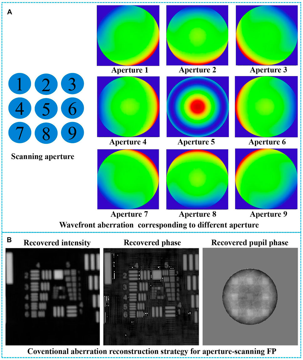
FIGURE 1. (A) The pupil functions corresponding to different apertures in the process of aperture scanning. (B) The recovered amplitude, phase, and pupil phase by the conventional aberration correction Fourier ptychography (FP) algorithm.
Methods
Based on this observation, we report a phase diversity (PD)-based FP (PDFP) scheme for varying aberration correction, as shown in Figure 2A. For the purpose of testing the reported method for macroscopic imaging, the light field exiting the sample is collected by the collimator where the light from objects is closer to real-world scenes, passing through the scannable aperture (or a spatial light modulator) and reimaged on the camera. A circular aperture is placed at the pupil plane of the optical system, and the different passbands of the optical field are transmitted to the image plane by scanning the sub-aperture. A sequence of low-resolution intensity images corresponding to different sub-apertures with different spatial frequency information of the light field is captured. To ensure acquiring redundant information to recover information merely from intensity images by the phase retrieval algorithm, the adjacent apertures should have a certain degree of overlap. With the use of the proposed method, the recovery of the full pupil function can be performed based on the PD algorithm by simply acquiring an in-focus image and an out-of-focus image with a big aperture that does not need to be moved to multiple positions. The sub-aperture pupil functions corresponding to different scannable positions are selected from the full pupil function and embedded in the FP reconstruction algorithm to correct the varying aberrations.
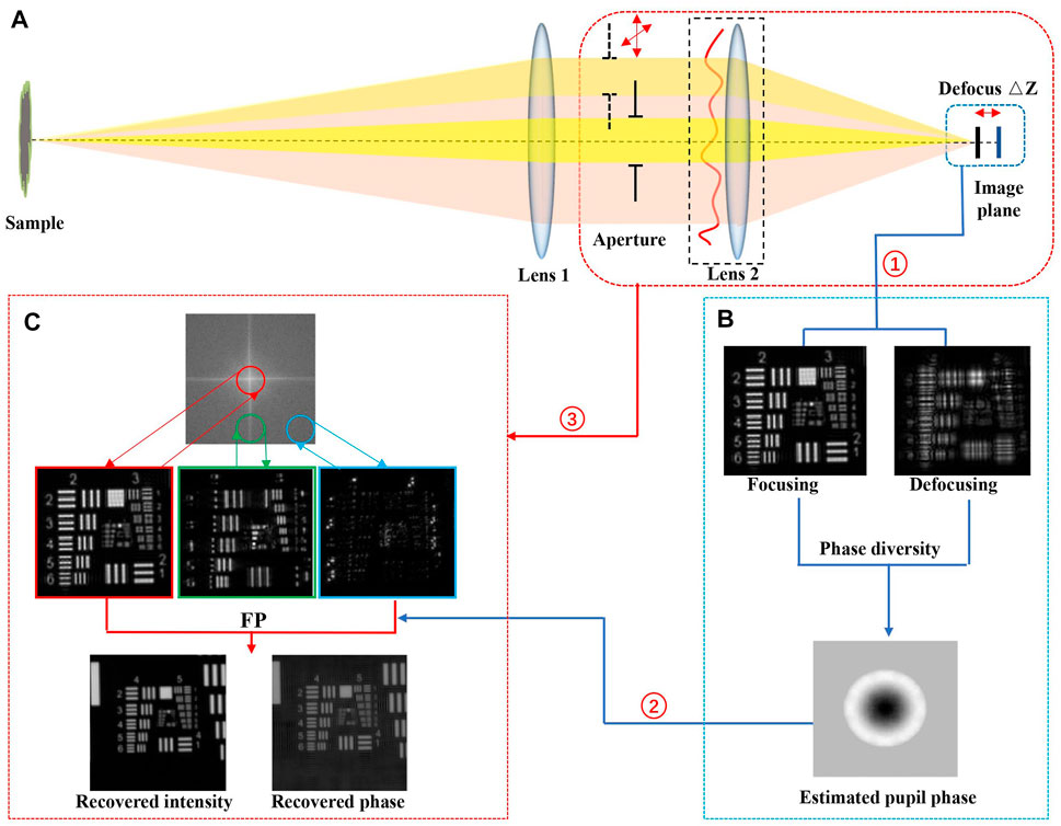
FIGURE 2. Phase diversity-based Fourier ptychography algorithm flow. (A) Phase diversity-based Fourier ptychography method. (B) The phase diversity algorithm. (C) Fourier ptychography algorithm with the corrected pupil functions.
PD algorithm is an unconventional imaging technique introduced by Gonsalves and Chidlaw [21], which uses a set of focused images and defocused images for the characterization of wavefront aberrations. The focused image is only degraded by systematic aberrations, while the defocused image is also affected by additional known defocus aberration. It should be noted that the PD technique relies on finding the aberrations that produce multiple images of the same sample with known diversities at the pupil. In addition to the traditional defocus diversities, the pupil differences can also come from wavelength diversities, spiral phase-mask diversities, and so on [22]. The PD algorithm can be applied to both point target and extended target for aberration recovery, enabling near-diffraction-limited imaging. Further details for the PD algorithm are available in [23].
The recovery process of the PDFP scheme is briefly outlined as follows. The algorithm sketch is shown in Figure 2.
1) Initialize the high-resolution image estimate: we assume the high-resolution sample is
2) Reconstruct the full pupil function: reconstruct the full pupil function
3) Generate a low-resolution sample image: an x–y motion stage is used to scan the small aperture at the Fourier plane, as shown in Figure 2A, and we capture an intensity image
where
4) Replace by the intensity measurement: the sample’s amplitude component
5) Update the Fourier spectrum: we apply Fourier transformation to this updated sample image
6) Repeat for other apertures: repeat steps 2–5 for different apertures and continue until the entire Fourier space has been modified with all the captured low-resolution images.
7) High-resolution image: repeat steps 2–6 until a convergent solution is achieved. At the end of the recovery process, the converged Fourier spectrum solution is transformed back to the spatial domain to obtain a high-resolution sample image.
A set of simulation experiments was carried out to evaluate the reconstructed results by the conventional FP, aberration correction FP, and our PDFP method, as shown in Figure 3. The conventional FP algorithm does not perform aberration correction, and the aberration correction FP algorithm is based on the traditional EPRY algorithm [7]. The focused image and defocused image are shown in Figures 3B,C. Figure 3A shows the real pupil phase, and Figure 3D shows the recovered pupil phase by the PD algorithm. In comparison, the PD method could recover the pupil phase from the measurements successfully. The low-resolution raw data are shown in Figure 3E1. The recovered results by the conventional FP, aberration correction FP, and our PDFP method are shown in Figures 3F1–H1. Figures 3E2–H2 are the close-ups of Figures 3E1–H1. Group 2 element 6 in Figures 3H1,H2 can be well resolved, which is impossible to discern in the other results. It is clear that the resolution of the recovered image resolution by our PDFP scheme is better than that of the conventional FP and aberration correction FP method.
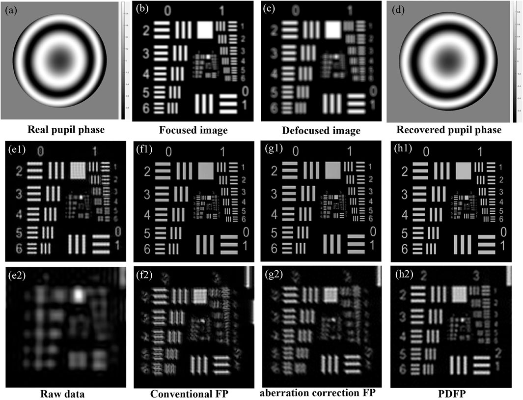
FIGURE 3. The comparison of simulation experimental results by the conventional Fourier ptychography (FP), aberration correction FP, and the proposed phase diversity-based FP (PDFP) method. (A) The real pupil phase. (B) The focused image. (C) The defocused image. (D) The recovered pupil phase by the phase diversity algorithm. (E1) The low-resolution raw data. (F1) The recovered results with conventional FP. (G1) The correction results by aberration correction FP. (H1) The correction results of our PDFP method. (E2–H2) Close-ups of panels (E1–H1).
Results
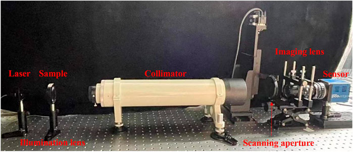
The experimental setup of the transmissive mode PDFP is shown in Figure 4. For the illumination, light from a laser (λ = 650 nm, bandwidth = 10 nm) was collimated into parallel light to illuminate the sample. A collimator (f = 500 mm) and illumination imaging lens (f = 75 mm) served as the forward and inverse Fourier transforming equipment. We used a CCD camera (6.5-μm pixel size, 16-bit dynamic range) to capture the sample’s low-resolution intensity images. Moreover, an x–y motion stage (repeat positioning accuracy is 3 μm) was used to scan the variable circular aperture. For testing the resolution of the system, a negative USAF1951 resolution target is used as the sample. The big aperture was set to 9 mm, and one focused image and one defocused image with a defocus distance of 0.35 mm were captured, which are used to restore the full pupil function. We chose a small aperture size of 2.5 mm (0.002 NA), where the region of overlapping ratio (in one dimension) with its adjacent aperture is 74%. We used 11 × 11 scanning steps to synthesize a 9-mm aperture (equaling an NA of NAsyn = 0.009, corresponding to 10.6-μm imaging resolution) and 121 low-resolution intensity images were captured. The method of scanning the aperture mechanically in our prototype is just a demonstration, and devices such as digital micromirror devices or spatial light modulators can be used instead [24; 25].
We compared the conventional FP, aberration correction FP, and the proposed PDFP method by imaging a USAF resolution target, as shown in Figure 5. The focused image and defocused image are shown in Figures 5A,B. The recovered wavefront by the PD algorithm is shown in Figure 5C. The raw image captured by the experimental setup is shown in Figure 5D1. And the resolution of this raw image (260-μm periodicity, corresponding to 39-μm imaging resolution) is limited by the small circular aperture. The reconstructed high-resolution images by the conventional FP, aberration correction FP, and our PDFP method are shown in Figures 5E1–G1. According to the Nyquist sampling theorem, a 5.3-μm pixel size is needed to fully characterize the image when the aperture is fully open (9 mm, corresponding to 10.6-μm resolution). However, the pixel size of our camera is 6.5 μm (typical specifications for commercial CCD sensors). Due to pixel aliasing limitations, the imaging resolution is 13 μm, which is twice of pixel size, as shown in Figure 5H1. Figures 5D2–H2 show line profiles of group 2 element 6 in Figures 5D1–H1. Figures 5D3–H3 show line profiles of group 3 element 2 in Figures 5D1–H1. And group 2 element 6 (71-µm periodicity, corresponding to 10.65-μm imaging resolution) can be resolved by our PDFP method, which matches well with the theoretical resolution defined by the synthesized NA, as shown in Figure 5G2. As we can see, due to the influence of aberration, group 2 element 6 in reconstruction results of the conventional FP and the aberration correction FP cannot be resolved well, as shown in Figures 5E2,F2. Moreover, the line profiles of group 3 element 2 by our PDFP method are significantly better than the other results. From the comparison, it can be seen that the reconstruction result of our PDFP method is better than the traditional FP algorithm, and the pixel aliasing problem can be avoided, resulting in image quality improved.
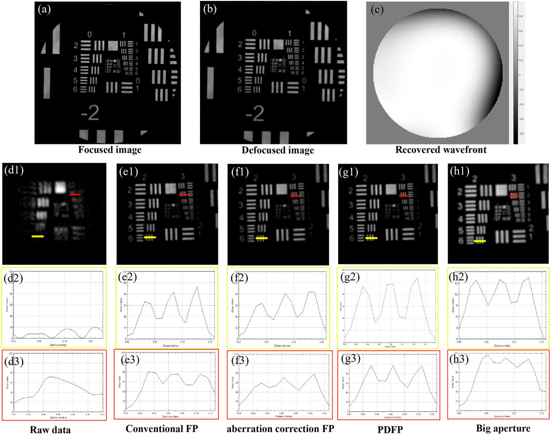
FIGURE 5. The experimental results by the conventional Fourier ptychography (FP), aberration correction FP, and the proposed phase diversity-based FP (PDFP) method. (A) The focused image. (B) The defocused image. (C) The recovered pupil phase. (D1) Low-resolution raw data. (E1) The recovered results with conventional FP. (F1) The result by aberration correction FP. (F1) The correction results of our PDFP method. (D2–H2) Line profiles of group 2 element 6 panels (D1–H1). (D3–H3) Line profiles of group 3 element 2.
Discussion
In summary, we implemented a PDFP imaging system that reconstructs the high-resolution image with aberration correction from a sequence of low-resolution intensity images. This PDFP configuration has a few advantages: 1) the thin-sample requirement of angularly varying illumination FP is circumvented, extending the FP scheme to macroscopic imaging settings. 2) System aberrations can be better corrected by shifting optical design complexity to computational algorithms, allowing the use of simpler optical systems with fewer optical surfaces for imaging. 3) The “pixel aliasing problem” can be solved by imposing a smaller aperture at the Fourier plane of the optical system. And the sensor (CCD or CMOS) with a larger pixel size can be used to provide better noise performance or bring down the cost of the imaging system. This method still has certain limiting factors in correcting aberrations, its time efficiency is low, and it is not applicable to some time-varying aberrations. This PDFP scheme reported in this work expands the scope of application for aperture-scanning FP, and its reflective mode can be used for semiconductor devices, metallic structures, ceramic surfaces, synthetic aperture imaging, and remote sensing.
Data Availability Statement
The original contributions presented in the study are included in the article/Supplementary Material, further inquiries can be directed to the corresponding author.
Author Contributions
All authors listed have made a substantial, direct, and intellectual contribution to the work and approved it for publication.
Funding
This work was supported by the National Natural Science Foundation of China (62075175, 61975254, 12104500) and Fundamental Research Funds for the Central Universities (Nos. XJS210506, JC2113).
Conflict of Interest
The authors declare that the research was conducted in the absence of any commercial or financial relationships that could be construed as a potential conflict of interest.
Publisher’s Note
All claims expressed in this article are solely those of the authors and do not necessarily represent those of their affiliated organizations, or those of the publisher, the editors, and the reviewers. Any product that may be evaluated in this article, or claim that may be made by its manufacturer, is not guaranteed or endorsed by the publisher.
References
1. Liu X, Qiao S, Ma Y. Highly Sensitive Methane Detection Based on Light-Induced Thermoelastic Spectroscopy with a 2.33 Μm Diode Laser and Adaptive Savitzky-Golay Filtering. Opt Express (2022) 30:1304–13. doi:10.1364/oe.446294
2. Ma Y, Hong Y, Qiao S, Lang Z, Liu X. H-shaped Acoustic Micro-resonator-based Quartz-Enhanced Photoacoustic Spectroscopy. Opt Lett (2022) 47:601–4. doi:10.1364/ol.449822
3. Liu X, Ma Y. Sensitive Carbon Monoxide Detection Based on Light-Induced Thermoelastic Spectroscopy with a Fiber-Coupled Multipass Cell. Chin Opt Lett (2022) 20:031201. doi:10.3788/col202220.031201
4. Liu F, Han P, Wei Y, Yang K, Huang S, Li X, et al. Deeply Seeing through Highly Turbid Water by Active Polarization Imaging. Opt Lett (2018) 43:4903–6. doi:10.1364/ol.43.004903
5. Zheng G, Horstmeyer R, Yang C. Wide-field, High-Resolution Fourier Ptychographic Microscopy. Nat Photon (2013) 7:739–45. doi:10.1038/nphoton.2013.187
6. Ou X, Horstmeyer R, Yang C, Zheng G. Quantitative Phase Imaging via Fourier Ptychographic Microscopy. Opt Lett (2013) 38:4845–8. doi:10.1364/ol.38.004845
7. Ou X, Zheng G, Yang C. Embedded Pupil Function Recovery for Fourier Ptychographic Microscopy. Opt Express (2014) 22:4960–72. doi:10.1364/oe.22.004960
8. Xiang D, Xu S, Horstmeyer R. Towards a Vectorial Treatment of Fourier Ptychographic microscopy. Computational Optical Sensing and Imaging. Washington, DC: Optical Society of America (2020)22‐26 June 2020.
9. Pan A, Zhang Y, Zhao T, Wang Z, Dan D, Lei M, et al. System Calibration Method for Fourier Ptychographic Microscopy. J Biomed Opt (2017) 22:1. doi:10.1117/1.JBO.22.9.096005
10. Pan A, Zhang Y, Wen K, Zhou M, Min J, Lei M, et al. Subwavelength Resolution Fourier Ptychography with Hemispherical Digital Condensers. Opt Express (2018) 26:23119–31. doi:10.1364/oe.26.023119
11. Sun J, Chen Q, Zhang J, Fan Y, Zuo C. Single-shot Quantitative Phase Microscopy Based on Color-Multiplexed Fourier Ptychography. Opt Lett (2018) 43:3365–8. doi:10.1364/ol.43.003365
12. Horstmeyer R, Chung J, Ou X, Zheng G, Yang C. Diffraction Tomography with Fourier Ptychography. Optica (2016) 3:827–35. doi:10.1364/optica.3.000827
13. Chowdhury S, Chen M, Eckert R, Ren D, Wu F, Repina N, et al. High-resolution 3D Refractive index Microscopy of Multiple-Scattering Samples from Intensity Images. Optica (2019) 6:1211–9. doi:10.1364/optica.6.001211
14. Guo K, Zhang Z, Jiang S, Liao J, Zhong J, Eldar YC, et al. 13-fold Resolution Gain through Turbid Layer via Translated Unknown Speckle Illumination. Biomed Opt Express (2018) 9:260–75. doi:10.1364/boe.9.000260
15. Dong S, Horstmeyer R, Shiradkar R, Guo K, Ou X, Bian Z, et al. Aperture-scanning Fourier Ptychography for 3D Refocusing and Super-resolution Macroscopic Imaging. Opt Express (2014) 22:13586–99. doi:10.1364/oe.22.013586
16. Ou X, Chung J, Horstmeyer R, Yang C. Aperture Scanning Fourier Ptychographic Microscopy. Biomed Opt Express (2016) 7:3140–50. doi:10.1364/boe.7.003140
17. Holloway J, Wu Y, Sharma MK, Cossairt O, Veeraraghavan A. SAVI: Synthetic Apertures for Long-Range, Subdiffraction-Limited Visible Imaging Using Fourier Ptychography. Sci Adv (2017) 3:e1602564. doi:10.1126/sciadv.1602564
18. Song P, Jiang S, Zhang H, Huang X, Zhang Y, Zheng G. Full-field Fourier Ptychography (FFP): Spatially Varying Pupil Modeling and its Application for Rapid Field-dependent Aberration Metrology. APL Photon (2019) 4:050802. doi:10.1063/1.5090552
19. Chung J, Martinez GW, Lencioni KC, Sadda SR, Yang. C. Computational Aberration Compensation by Coded-Aperture-Based Correction of Aberration Obtained from Optical Fourier Coding and Blur Estimation. Optica (2019) 6:647–61. doi:10.1364/optica.6.000647
20. Chung J, Kim J, Ou X, Horstmeyer R, Yang C. Wide Field-Of-View Fluorescence Image Deconvolution with Aberration-Estimation from Fourier Ptychography. Biomed Opt Express (2016) 7:352–68. doi:10.1364/boe.7.000352
21. Robert A. Gonsalves. "Phase Retrieval and Diversity in Adaptive Optics. Opt Eng (1982) 21:215829.
22. Echeverri-Chacón S, Restrepo R, Cuartas-Vélez C, Uribe-Patarroyo N. Vortex-enhanced Coherent-Illumination Phase Diversity for Phase Retrieval in Coherent Imaging Systems. Opt Lett (2016) 41:1817–20.
23. Zhang P, Yang C, Xu Z, Cao Z, Mu Q, Xuan L. High-accuracy Wavefront Sensing by Phase Diversity Technique with Bisymmetric Defocuses Diversity Phase. Sci Rep (2017) 7:15361–10. doi:10.1038/s41598-017-15597-x
24. Lofdahl MG, Kendrick RL, Harwit A, Mitchell KE, Duncan AL, Seldin JH, et al. Phase Diversity experiment to Measure Piston Misalignment on the Segmented Primary Mirror of the Keck II Telescope. Space Telescopes Instr V (1998) 3356:1190–1201. doi:10.1117/12.324519
Keywords: Fourier ptychography, varying aberration, phase diversity, aperture scanning, high-resolution imaging
Citation: Xiang M, Pan A, Liu J, Xi T, Guo X, Liu F and Shao X (2022) Phase Diversity-Based Fourier Ptychography for Varying Aberration Correction. Front. Phys. 10:848943. doi: 10.3389/fphy.2022.848943
Received: 05 January 2022; Accepted: 07 February 2022;
Published: 16 March 2022.
Edited by:
Yufei Ma, Harbin Institute of Technology, ChinaReviewed by:
He Xiaoliang, Jiangnan University, ChinaJianming Wen, Kennesaw State University, United States
Copyright © 2022 Xiang, Pan, Liu, Xi, Guo, Liu and Shao. This is an open-access article distributed under the terms of the Creative Commons Attribution License (CC BY). The use, distribution or reproduction in other forums is permitted, provided the original author(s) and the copyright owner(s) are credited and that the original publication in this journal is cited, in accordance with accepted academic practice. No use, distribution or reproduction is permitted which does not comply with these terms.
*Correspondence: Fei Liu, ZmVpbGl1QHhpZGlhbi5lZHUuY24=
 Meng Xiang
 An Pan
 Jinpeng Liu
 Teli Xi
 Xin Guo1