 Xinrong Zhou1
 Zhenhua Chen
94% of researchers rate our articles as excellent or good
Learn more about the work of our research integrity team to safeguard the quality of each article we publish.
Find out more
ORIGINAL RESEARCH article
Front. Phys., 04 January 2023
Sec. Optics and Photonics
Volume 10 - 2022 | https://doi.org/10.3389/fphy.2022.1097125
This article is part of the Research TopicAdvances in Optical Imaging Techniques for Microscopy and NanotechnologyView all 7 articles
A collinear backscattering Mueller matrix (CBMM) imaging system has clear advantages in the detection of bulk biological tissues, which are highly scattering and depolarizing. Due to the double-pass configuration and noise in the system, the calibration of a collinear backscattering Mueller matrix imaging system is usually complex and of poor accuracy. In this work, we propose an alternative modified eigenvalue calibration method (ECM) based on the equivalent standard sample. For better noise suppression and higher calibration accuracy, we design the distribution of polarization states over the Poincaré sphere and solve for the parameters of equivalent standard samples by means of an optimization. Compared to other variants of the eigenvalue calibration method used in the double-pass system, the accuracy of the proposed method is improved by more than 40 times. The comparison results with the error model-based calibration methods indicate that the modified eigenvalue calibration method generally gives the best accuracy and precision, as well as the best reliability.
The Mueller matrix, which describes the transformation of the state of polarization (SOP) of light, contains rich information about the microstructure and properties of an object [1–3]. As a non-invasive, non-contact, and label-free detection method, the Mueller matrix imaging technology has unique advantages in biomedical detection: it can provide extra information about the sample while being compatible with many existing optical systems, for example, microscopes and endoscopes [4]. Recently, the biomedical and clinical applications of the Mueller matrix imaging technique have attracted substantial attention [5, 6], such as the early detection of cancerous tissues [7–9].
Generally, a thin sample can be detected with a transmission Mueller matrix (TMM) imaging system [10], while a bulky sample which is highly scattering and depolarizing, is more appropriate for detection by a collinear backscattering Mueller matrix (CBMM) imaging system [11]. The calibration of a TMM system based on dual-rotating retarders is easy due to its simple optical system. One of the most popular calibration methods used to calibrate the TMM system is the analysis calibration method (ACM), which builds an error model with five main systemic errors and obtains the error values by the Fourier analysis method [12–14]. The calibration of a CBMM system is more complex due to the variety of error sources, for example, the parasitic polarization of the beam splitter also affects the SOP of light. In our previous work, to calibrate the CBMM system we proposed a numerical calibration method (NCM) that takes into account the parasitic polarization of the beam splitter and solves the system errors numerically by Levenberg–Marquardt (LM) algorithm [15]. However, the systematic error model-based calibration methods have the following drawbacks, they require a priori knowledge of the system and are prone to over-calibration when the systematic error model is overly complex.
Different from the error model-based calibration methods, the eigenvalue calibration method (ECM) does not require any priori information such as the polarization states produced in the system [16, 17]. As a general method for the calibration of Mueller matrix imaging systems, the ECM has shown an increase in popularity [18]. However, due to the complex double-pass configuration, the original ECM is not suitable for the calibration of the CBMM system and some modifications of the original ECM are necessary [19]. Besides, the ECM is inefficient in the case of low signal-to-noise ratio (SNR) since it assumes that there is no noise in the measurement system [20].
In this paper, we propose an alternative modified ECM for the CBMM system. Unlike other variants of the ECM, we simplify the double-pass calibration to a single-pass calibration by the mirror symmetry and the concept of the equivalent standard sample; it is much simpler in theory as it does not need to address issues such as matrix reciprocity and eigenvalue squaring. For better calibration performance, we optimize the distribution of analysis states over the Poincaré sphere taking into account the inherent constraints of polarization modulators, and calibrate the parameters of equivalent standard samples by means of an optimization. To compare the performance of the modified ECM and the error model-based calibration methods, a series of experiments with various samples are performed.
The optical path diagram of the CBMM system is shown in Figure 1. A LED (center wavelength = 610 nm and FWHM = 20 nm) is used as the light source in the system. The output beam from the LED is collimated by an objective lens (L1) and a convex lens (L2). P1 and P2 are linear polarizers (LPVISE100-A, 400–700 nm, Thorlabs, Inc., U.S.). R1 and R2 are zero-order quarter-wave plates (GCL-060402, 633 nm, Daheng, Optic, China). The polarization state generator (PSG) consists of a fixed polarizer (P1) and a rotating quarter-wave plate (R1), while the polarization state analyzer (PSA) consists of a rotating polarizer (P2) and a rotating quarter-wave plate (R2). Wave plates R1, R2 and polarizer P2 are driven by three servo motors (PRM1Z8E, Thorlabs, Inc., U.S.), respectively. The polarization-modulated beam is reflected by the sample at normal incidence after passing through a beam splitter (GCC-403102, Daheng, Optic, China), and then the backscattered light is imaged by a charged couple device (CCD) camera (PCO. panda 4.2, 16bit, Inc., Germany) after passing through the PSA and a low numerical aperture (NA) objective lens (L3).
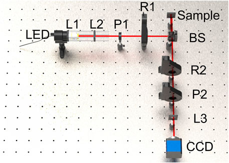
FIGURE 1. Optical path diagram of the collinear backscattering Mueller matrix imaging system.
Previous studies on the eigenvalue calibration method in the double-pass system needed to consider the complex reciprocal relationship between the Mueller matrix of the reflection mirror and the Mueller matrix of the sample [19, 21]. In this work, we propose an alternative modified ECM that effectively simplifies the calibration theory by utilizing the mirror symmetry and equivalent standard samples.
In the absence of depolarization, the Mueller matrices of polarizers and wave-plates can be written uniformly as follows [22]:
where
Given the properties of mirror symmetry, the double-pass process for an arbitrary standard sample can be simplified to the left multiplication of Mueller matrix
where
Similar to the calibration process for single-pass system, air,
where W and A are the polarization generation matrix and the polarization analysis matrix, respectively, and
Define matrix
where superscript ‘†’ denotes the Moore-Penrose pseudo-inverse. Notice that
where
Left multiplying Eq. 6 on both sides by matrix W, one obtains:
which is in the form of the Sylvester equation [18, 23]. Using the vec operator [24] and the Kronecker product (
where the superscript ‘T’ represents the transpose. To uniquely determine the
Theoretically, the matrix L should only have one null eigenvalue and the corresponding eigenvector is
After calibration, the backscattering Mueller matrix of an arbitrary sample can be calculated directly from the detected intensity matrix of sample (
The ECM assumes that all the Mueller matrices of standard samples are perfectly known. However, due to noise in the system, the reconstruction of the equivalent Mueller matrices by calculating the ratios of eigenvalues becomes inefficient; in fact, even if the whole system is perfectly known, the noise still causes the SOP of light to deviate from the theoretical value, thus decreasing the calibration performance. For higher calibration accuracy, two optimizations for the modified ECM are introduced: designing a reasonable polarization state analyzer (PSA) to restrain noise and calculating the parameters of the equivalent Mueller matrices by a noise insensitive method.
Relevant studies have shown that the optimization of analysis states over the Poincaré sphere can be described by the spherical-2 designs [26]. Considering each row of the
Two quantitative indicators the condition number (CN) and the equally weighted variance (EWV) are used to estimate the performance of PSA [28, 29],
where the
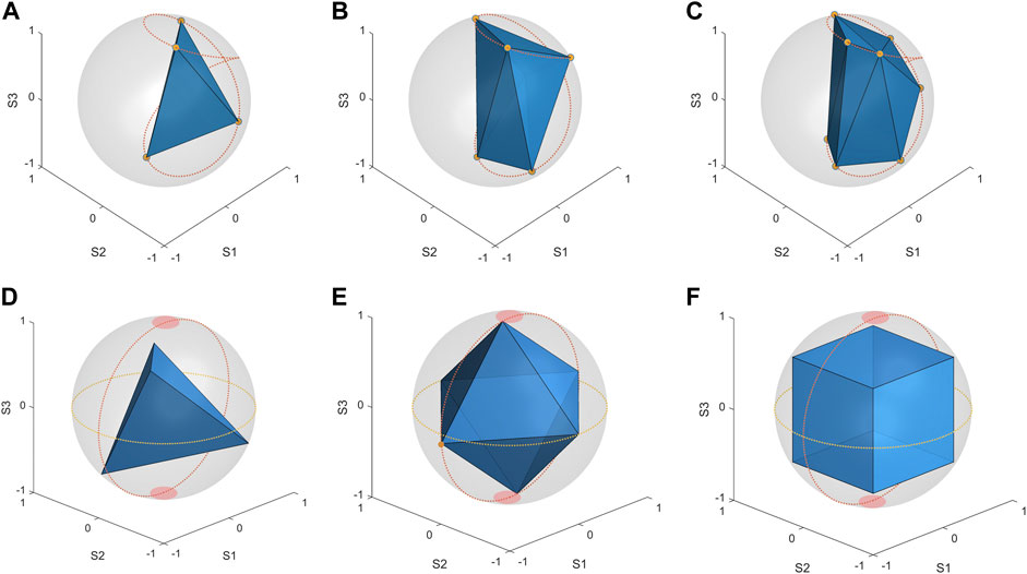
FIGURE 2. (A–C) Optimal modulation frames of a FP based PSA for N = 4, 6, 8, (D–F) optimal modulation frames of a RP based PSA for N = 4, 6, 8.
To compare the performance of different optimal modulation frames in the Mueller matrix measurements, a homogeneous wave plate is used as the sample and its Mueller matrix image is measured under different polarization analysis modes. Then the phase retardance image of the sample for each of optimal modulation frames is calculated by Mueller matrix polar decomposition (MMPD) method, respectively [31]. The SNR calculated for each phase retardance image is shown in Table 1. The CNs of the RP mode can reach
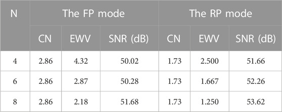
TABLE 1. The SNRs of measurement results in different configurations.
In the previous calibration study, the ellipsometric parameters of standard samples are obtained by calculating the ratios of the eigenvalues of the matrix
where
For the same set of experimental data, we compared the accuracy and relative error (RE) of the parameters of equivalent standard samples calculated by different methods, as shown in Table 2. It can be seen that the RE calculated by the previous method is as high as 5%, while the RE calculated by means of an optimization is less than 1.6%, only 1/3 of the former. In other words, the accuracy of the proposed method to reconstruct the Mueller matrix of the equivalent standard sample is three times that of the previous method.
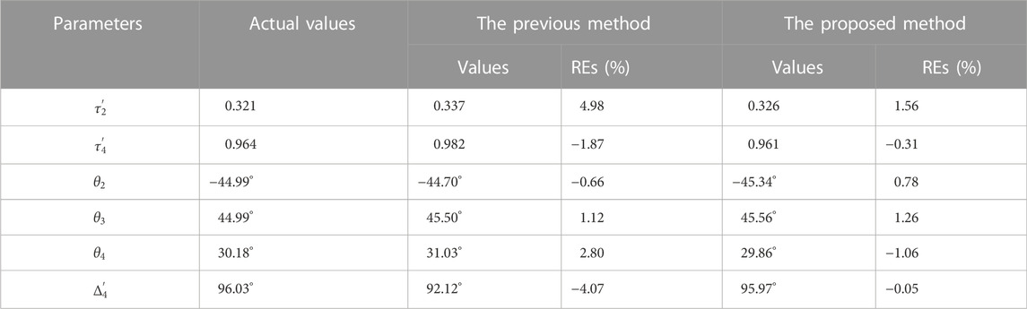
TABLE 2. Parameters of equivalent standard samples calculated by different methods.
The accuracy of the equivalent standard sample has a direct impact on the final accuracy of the calibration. The comparison results of the eigenvalues of Matrix L calculated with different methods are shown in Figure 3. Thanks to the more accurate Mueller matrices of equivalent standard samples, the minimum eigenvalue of the proposed method is 1.45E-05, which is two orders of magnitude lower than that of the previous method. In ECM, the error estimator
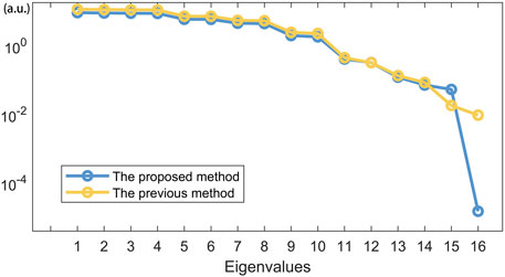
FIGURE 3. Comparison of the eigenvalues calculated by different methods.
To compare the calibration performance of the modified ECM with the error model-based methods such as the ACM and NCM, we measured several samples including a polarizer, a wave plate, and a well-aligned silk sample. For the modified ECM, we adopt the RP-8 polarization state analysis mode and reconstruct the Mueller matrices of equivalent standard samples by means of an optimization with the genetic algorithm. For the ACM and NCM, the quarter-wave plates in PSG and PSA rotate synchronously with a fixed ratio of angular velocity 1:5 and a total of 30 measurements are required to calculate the Mueller matrix image of the sample. During calibration with the ACM and the NCM, the two polarizers in the PSG and PSA are fixed, in other words the PSA is in the FP mode. Since the transmission Mueller matrices of transparent samples can be accurately measured in a calibrated TMM system, their true equivalent Mueller matrices which can be calculated by Eq. 3 are in fact well-known, namely
To estimate the performance of different calibration methods, four accuracy indicators the average root mean square error (
where the “average” refers to the average over all pixels in the selected area of the Mueller matrix image, D and R represent the diattenuation function and the phase retardance function defined in the MMPD, respectively.
The Mueller Matrix images of a quarter-wave plate (GCL-060403, 488 nm, Daheng, Optic, China) and a polarizer (LPVISE100-A, 400–700 nm, Thorlabs, Inc., U.S.) are measured in the CBMM system based on three different calibration methods. The comparison results are shown in Figure 4. It is clear that the modified ECM has the best calibration performance, with the NCM the second best and the ACM the worst. For the wave plate sample, the
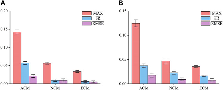
FIGURE 4. The calibration performance comparison of three calibration methods with different samples, (A) a wave plate sample, (B) a polarizer sample.
In the next experiment, a well-aligned silk sample is selected as the experimental sample, as shown in Figure 5. Because of its highly scattering property and typical birefringent nature, the silk sample is an ideal object of study for the Mueller matrix imaging system [34]. As the illumination light and detection light are collinear in the CBMM system, several polarization parameters independent of the azimuth angle of the sample, i.e., rotation invariant indicators can be derived from the Mueller matrix [35]. Obviously, if a CBMM system is well calibrated, the rotation invariant indicators separated from different azimuthal regions of a circularly symmetric sample should be constant; on the other hand, when a CBMM system is not well calibrated, these rotation invariant indicators may still be orientation dependent. Considering the circular symmetry of the silk sample, it is possible to estimate the calibration performance of different calibration methods in the view of symmetry.
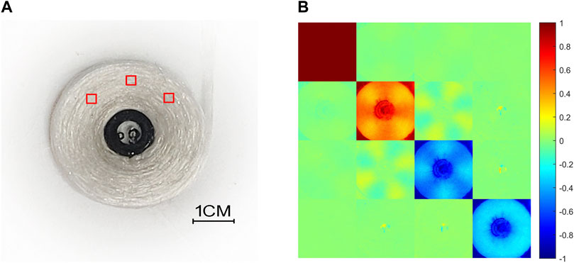
FIGURE 5. A well-aligned silk sample (A) and its Mueller matrix image (B).
In the experiment, we select three different azimuthal regions on the silk sample, i.e.,
where
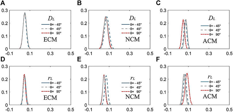
FIGURE 6. Frequency distribution images of different rotation invariant indicators, (A–C) rotation invariant indicator
It is clear that the rotation invariant curves obtained by the modified ECM for different azimuthal regions are perfectly coincident with each other, while the results of the error model-based calibration methods are partially non-overlap. In other words, the rotation invariant indicators measured by the modified ECM do not depend on the azimuth angle of samples, whereas the results given by the NCM and the ACM are still azimuth dependent. As a result, it can be deduced that only the calibration result of the modified ECM is reliable from the view of symmetry. In fact, the calibration performance of the NCM and the ACM depends on their error models, however, it is difficult for a theoretical error model to accurately describe the actual measurement system. In addition, solving an error model that is overly complex may lead to over-calibration, which affects the accuracy of the calibration. The major advantage of the modified ECM is that it does not require modelling the errors in the system, hence it is more suitable for the complex CBMM system. Thanks to the optimal modulation frames for the PSA and the optimization-based Mueller matrix reconstruction method, the modified ECM gives the best calibration performance in the CBMM system.
In this paper, based on the eigenvalue calibration method we propose a simple modified ECM to calibrate the CBMM system configured in double-pass. In the modified ECM, we transform the complex double-pass calibration problem into a simple single-pass form by using mirror symmetry and the concept of the equivalent standard sample. To suppress the effect of noise on calibration accuracy, we design the distribution of polarization states over Poincaré sphere considering the inherent constraints of polarization modulators, and reconstruct the Mueller matrix of equivalent standard samples by means of an optimization. It is found that an optimal PSA can effectively improve the SNR of the measurement data and the optimization-based Mueller matrix reconstruction method is more robust against noise than the direct calculation method. After optimization, the accuracy of the modified method is 40 times better than the previous variants of the ECM. The comparison results with the error model-based calibration methods indicate that the modified ECM has clear advantages in the calibration of the CBMM system with higher accuracy and superior reliability.
The raw data supporting the conclusions of this article will be made available by the authors, without undue reservation.
All authors listed have made a substantial, direct, and intellectual contribution to the work and approved it for publication.
Guang Dong Basic and Applied Basic Research Foundation (2019A1515111128); National Natural Science Foundation of China (61575067, 81871395).
The authors declare that the research was conducted in the absence of any commercial or financial relationships that could be construed as a potential conflict of interest.
All claims expressed in this article are solely those of the authors and do not necessarily represent those of their affiliated organizations, or those of the publisher, the editors and the reviewers. Any product that may be evaluated in this article, or claim that may be made by its manufacturer, is not guaranteed or endorsed by the publisher.
1. Ramella-Roman JC, Saytashev I, Piccini M. A review of polarization-based imaging technologies for clinical and preclinical applications. J Opt (United Kingdom) (2020) 22:123001. doi:10.1088/2040-8986/abbf8a
2. He C, Chang J, Salter PS, Shen Y, Dai B, Li P, et al. Revealing complex optical phenomena through vectorial metrics. Adv Photon (2022) 4:1–9. doi:10.1117/1.ap.4.2.026001
3. Ghosh N. Tissue polarimetry: Concepts, challenges, applications, and outlook. J Biomed Opt (2011) 16:110801. doi:10.1117/1.3652896
4. He C, He H, Chang J, Chen B, Ma H, Booth MJ. Polarisation optics for biomedical and clinical applications: A review. Light Sci Appl (2021) 10:194. doi:10.1038/s41377-021-00639-x
5. He H, Liao R, Zeng N, Li P, Chen Z, Liu X, et al. Mueller matrix polarimetry-An emerging new tool for characterizing the microstructural feature of complex biological specimen. J Light Technol (2019) 37:2534–48. doi:10.1109/JLT.2018.2868845
6. Qi J, Elson DS. Mueller polarimetric imaging for surgical and diagnostic applications: A review. J Biophotonics (2017) 10:950–82. doi:10.1002/jbio.201600152
7. Wang Y, He H, Chang J, He C, Liu S, Li M, et al. Mueller matrix microscope: A quantitative tool to facilitate detections and fibrosis scorings of liver cirrhosis and cancer tissues. J Biomed Opt (2016) 21:071112. doi:10.1117/1.jbo.21.7.071112
8. Du E, He H, Zeng N, Sun M, Guo Y, Wu J, et al. Mueller matrix polarimetry for differentiating characteristic features of cancerous tissues. J Biomed Opt (2014) 19:076013. doi:10.1117/1.jbo.19.7.076013
9. Pierangelo A, Benali A, Antonelli M-R, Novikova T, Validire P, Gayet B, et al. Ex-vivo characterization of human colon cancer by Mueller polarimetric imaging. Opt Express (2011) 19:1582. doi:10.1364/oe.19.001582
10. Arteaga O, Baldrís M, Antó J, Canillas A, Pascual E, Bertran E. Mueller matrix microscope with a dual continuous rotating compensator setup and digital demodulation. Appl Opt (2014) 53:2236. doi:10.1364/ao.53.002236
11. Fu Y, Chen Z, Tang Z, Ji Y. Removing the influence of the angle of incidence in a dual rotating retarder Mueller matrix polarimeter. Appl Opt (2021) 60:8472. doi:10.1364/ao.435283
12. Azzam RMA. Photopolarimetric measurement of the Mueller matrix by Fourier analysis of a single detected signal. Opt Lett (1978) 2:148. doi:10.1364/ol.2.000148
13. Goldstein DH, Chipman RA. Error analysis of a Mueller matrix polarimeter. J Opt Soc Am A (1990) 7:693. doi:10.1364/josaa.7.000693
14. Chenault DB, Pezzaniti JL, Chipman RA. Muller matrix algorithms. Proc SPIE (1992) 1746:231. doi:10.1117/12.138793
15. Chen Z, Meng R, Zhu Y, Ma H. A collinear reflection Mueller matrix microscope for backscattering Mueller matrix imaging. Opt Lasers Eng (2020) 129:106055. doi:10.1016/j.optlaseng.2020.106055
16. Compain E, Poirier S, Drevillon B. General and self-consistent method for the calibration of polarization modulators, polarimeters, and Mueller-matrix ellipsometers. Appl Opt (1999) 38:3490. doi:10.1364/ao.38.003490
17. De Martino A, Garcia-Caurel E, Laude B, Drévillon B. General methods for optimized design and calibration of Mueller polarimeters. Thin Solid Films (2004) 455(456):112–9. doi:10.1016/j.tsf.2003.12.052
18. Macías-Romero C, Török P. Eigenvalue calibration methods for polarimetry. J Eur Opt Soc (2012) 7:12004. doi:10.2971/jeos.2012.12004
19. Lara D, Dainty C. Axially resolved complete Mueller matrix confocal microscopy. Appl Opt (2006) 45:1917–30. doi:10.1364/AO.45.001917
20. Hu H, Garcia-Caurel E, Anna G, Goudail F. Maximum likelihood method for calibration of Mueller polarimeters in reflection configuration. Appl Opt (2013) 52:6350–8. doi:10.1364/AO.52.006350
21. Sheng S, Chen X, Chen C, Zhuang J, Wang C, Gu H, et al. Eigenvalue calibration method for dual rotating-compensator Mueller matrix polarimetry. Opt Lett (2021) 46:4618. doi:10.1364/ol.437542
22. Cox LJ. Ellipsometry and polarized light. Opt Acta Int J Opt (1978) 25:270–1. doi:10.1080/713819761
23. Zhou B, Duan GR. On the generalized Sylvester mapping and matrix equations. Syst Control Lett (2008) 57:200–8. doi:10.1016/j.sysconle.2007.08.010
24. Henderson HV, Searle SR. Vec and vech operators for matrices, with some uses in jacobians and multivariate statistics. Can J Stat (1979) 7:65–81. doi:10.2307/3315017
25. Brewer JW. Kronecker products and matrix calculus in system theory. IEEE Trans Circuits Syst (1978) 25:772–81. doi:10.1109/TCS.1978.1084534
26. Foreman MR, Favaro A, Aiello A. Optimal frames for polarization state reconstruction. Phys Rev Lett (2015) 115:263901–6. doi:10.1103/PhysRevLett.115.263901
27. Zhao Q, Huang T, Hu Z, Bu T, Liu S, Liao R, et al. Geometric optimization method for a polarization state generator of a Mueller matrix microscope. Opt Lett (2021) 46:5631. doi:10.1364/ol.441492
28. Ambirajan A. Optimum angles for a polarimeter: Part II. Opt Eng (1995) 34:1656. doi:10.1117/12.202098
29. Peinado A, Lizana A, Vidal J, Iemmi C, Campos J. Optimized Stokes polarimeters based on a single twisted nematic liquid-crystal device for the minimization of noise propagation. Appl Opt (2011) 50:5437–45. doi:10.1364/AO.50.005437
30. Shapiro J. Genetic algorithms in machine learning. In: Advanced course on artificial intelligence. p. 146. doi:10.1007/3-540-44673-7_7
31. Lu S-Y, Chipman RA. Interpretation of mueller matrices based on polar decomposition retardance : A review. J Opt Soc Am A (1996) 13:1106–13. doi:10.1364/josaa.13.001106
32. Sabatke DS, Descour MR, Dereniak EL, Sweatt WC, Kemme SA, Phipps GS. Optimization of retardance for a complete Stokes polarimeter. Opt Lett (2000) 25:802. doi:10.1364/ol.25.000802
33. Foreman MR, Goudail F. On the equivalence of optimization metrics in Stokes polarimetry. Opt Eng (2019) 58:1. doi:10.1117/1.oe.58.8.082410
34. He H, Sun M, Zeng N, Du E, Liu S, Guo Y, et al. Mapping local orientation of aligned fibrous scatterers for cancerous tissues using backscattering Mueller matrix imaging. J Biomed Opt (2014) 19:106007. doi:10.1117/1.jbo.19.10.106007
35. Gil JJ. Invariant quantities of a Mueller matrix under rotation and retarder transformations. J Opt Soc Am A (2016) 33:52. doi:10.1364/josaa.33.000052
Keywords: Mueller matrix, polarization imaging, calibration, optimization, backscattering
Citation: Zhou X, Fu Y, Liao H, Chen Z, Ji Y and Tang Z (2023) Calibration of a collinear backscattering Mueller matrix imaging system. Front. Phys. 10:1097125. doi: 10.3389/fphy.2022.1097125
Received: 19 November 2022; Accepted: 15 December 2022;
Published: 04 January 2023.
Edited by:
Chao He, University of Oxford, United KingdomReviewed by:
Yifei Ma, University of Oxford, United KingdomCopyright © 2023 Zhou, Fu, Liao, Chen, Ji and Tang. This is an open-access article distributed under the terms of the Creative Commons Attribution License (CC BY). The use, distribution or reproduction in other forums is permitted, provided the original author(s) and the copyright owner(s) are credited and that the original publication in this journal is cited, in accordance with accepted academic practice. No use, distribution or reproduction is permitted which does not comply with these terms.
*Correspondence: Zhenhua Chen, Y2hlbnpoQG5qdS5lZHUuY24=; Yanhong Ji, aml5aEBzY251LmVkdS5jbg==
Disclaimer: All claims expressed in this article are solely those of the authors and do not necessarily represent those of their affiliated organizations, or those of the publisher, the editors and the reviewers. Any product that may be evaluated in this article or claim that may be made by its manufacturer is not guaranteed or endorsed by the publisher.
Research integrity at Frontiers
Learn more about the work of our research integrity team to safeguard the quality of each article we publish.