- 1State Key Laboratory of Simulation and Regulation of Water Cycle in River Basin, Beijing, China
- 2Huaneng Lancang River Hydropower Co., Ltd., Kunming, China
- 3China Power Construction Group Kunming Survey, Design and Research Institute Co., Ltd., Kunming, China
- 4China University of Geosciences (Beijing), Beijing, China
On the basis of the numerical manifold method, this work introduces the concept of stress intensity factor at the crack tip in fracture mechanics and proposes the utilisation of artificial joint technology to ensure the accuracy of joint geometric dimensions in the element generation of the numerical manifold method. The contour integral method is used to solve the stress intensity factor at the joint tip, and the failure criterion and direction of crack propagation at the joint tip are determined. Element reconstruction and crack tracking are implemented in crack propagation, and a simulation programme of the entire process of deformation, failure, propagation and coalescence of jointed rock masses is developed. The rationality of the proposed method is verified by performing the typical uniaxial compression test and direct shear test.
Introduction
As a product of long-term geological tectonic movements, rock masses contain various discontinuous structural planes, such as faults, joints, bedding and fractures [1–5]. As these structural planes intersect with one another, specific rock mass structures are formed. The complexity of a rock mass structure determines its failure mechanism and engineering mechanical properties, such as strength and deformation. Many engineering cases show that the deformation, failure and instability of rock masses are usually caused by the deformation, failure, propagation and even coalescence of their internal structural planes [6–9]. Therefore, the study of the evolution law of the deformation, failure, propagation and coalescence of structural planes in jointed rock masses offers great scientific significance and application value.
With the rapid development of computer technology, numerical simulation methods have been effectively applied to study engineering mechanical properties of jointed rock masses with multiple fractures. As a result of the different calculation and analysis media, numerical simulations are conducted using methods based on continuous media (FEM, BEM, and FDM), discrete media (DDA and DEM) and discontinuous media (NMM) [5,10,11].
Numerical simulation methods based on discontinuous media (NMM) [10,11] integrate the advantages of DDA and FEM methods and combine the contact calculation of discontinuous mass and stress–strain analysis in mass by using two meshes (physical and mathematical meshes). The use of two meshes separates the integral region from the calculation region, which can overcome the sharp increase of calculation caused by element adjustment in crack propagation. Such method is suitable for the simulation analysis of discontinuous media, such as jointed rock masses [12–16].
Based on the numerical manifold method, a simulation method for the failure process of jointed rock mass is proposed in this paper. Outstanding advantages of the method used in this paper are as follows: 1) The element generation method of numerical manifold method is improved by using virtual joint technology, and the calculation accuracy is improved. 2) The basic concept of fracture mechanics is introduced, the joint failure criterion and crack tracking technology are proposed, and the whole process of deformation and failure of jointed rock mass is simulated. 3) The improvement of numerical manifold method makes it more suitable for the simulation of jointed rock mass.
Simulation of Deformation Failure Process of Jointed Rock Masses Based on the Numerical Manifold Method
Artificial Joint Technique for Element Generation Based on the Numerical Manifold Method
The mesh generation mode and mass search algorithm in the numerical manifold method are similar to those in DDA. To ensure the determinacy of the topological relationship in the search process, the algorithm cuts off a part of the joint that does not coalesce the mathematical element (triangle) to change the geometric length of the joint. Cutting is an efficient and practical method for models based on discrete media, but it is obviously inappropriate for jointed rock masses whose stress and deformation characteristics at the joint tips should be considered. As described in this section, artificial joint technology is used herein to ensure the accuracy of geometric dimensions when generating physical elements. The steps are summarised as follows: 1) When searching for a two-dimensional mass, generate a new matrix and retain the line segment that has been cut. 2) After generating the physical element, establish the correlation between the line segment that has been cut and the physical element. 3) For the physical element containing the line segment that has been cut, perform artificial joint processing and then record all artificial joints. Thereafter, simulate the continuous boundary by assigning large intensity parameters to the artificial joints in the calculation process. 4) Input the artificial joint information, original geometric dimensions and boundaries of the mathematical elements to regenerate the physical and mathematical elements.
The processing mode of artificial joints is as follows: 1) If only one line segment has been cut in the physical element, then extend such line segments until it intersects with the physical element. The extended line segment is an artificial joint. 2) If two line segments have been cut in the physical element, then connect the two endpoints of the two segments in the element to form a line segment, which serves as the artificial joint. 3) If three line segments have been cut in the physical element, then connect the three endpoints of the three segments in the element to form three line segments. Out of the three line segments, two that do not intersect the line segments having been cut are selected as the artificial joints. 4) If the physical element contains more than four line segments that have been cut, then connect the endpoints in the element to form a group of line segments, and delete the line segments intersecting the line segments that have been cut. According to the principles of including all internal endpoints and non-intersecting line segments, identify all possible line segment combinations and select the combination with the least number of line segments as the artificial joint. The example in Figure 1 shows that the geometric dimension error without virtual joint technology can reach 43%, and the geometric dimension error with virtual joint technology proposed in this paper is 0%.
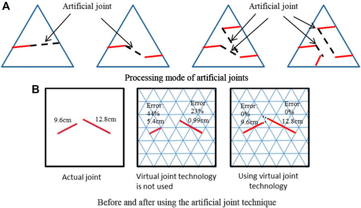
FIGURE 1. Artificial joint technique. (A) Processing mode of artificial joints. (B) Before and after using the artificial joint technique.
Use of Contour Integral Method to Solve the Stress Intensity Factor at the Joint Tip
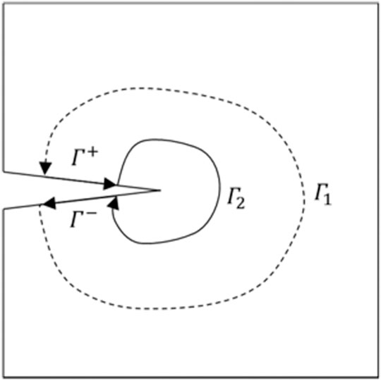
The calculation of the stress intensity factor is the key technique in the simulation of the failure process of jointed rock masses. This study uses the contour integral method to solve the stress intensity factor at the joint tip and defines a contour away from the crack tip and around the crack tip in a counter-clockwise direction. An auxiliary stress field and a displacement field are constructed, and the stress intensity factors
[17,18] reciprocal theorem of work under the premise that the volume force applied to the elasticity of an isotropic body is ignored is shown in Eq. 2.
In the above equation,
If the auxiliary displacement field is applicable to the stress field, then the stress intensity factors
As mentioned previously, the auxiliary stress field and displacement field of a contour integral are the main factors affecting the intensity factor. On the basis of the two functions of the complex variables proposed by [18], the current work constructs an auxiliary stress field and a displacement field at the crack tip [18]. used
G is the shear modulus, and
For semi-infinite plane cracks, the functions of complex variables
In the same way, let
The Eq. 8 between the contour
From Eq. 8, the far-field contour at the crack tip can be written as the linear expression Eq. 9 of
Determination of Failure Criterion and Failure Direction
The stress intensity factor at the joint tip is calculated using the contour integral method. The failure criterion and direction of crack propagation at the joint tip can be determined according to the principle of maximum circumferential stress. The auxiliary displacement field and stress field constructed by the contour integral method are only applicable to a single crack without considering the interaction of the stress field at the multi-crack tip. Therefore, this study determines the failure criterion of a rock mass and joint tip to simulate the failure process of jointed rock masses.
The failure criterion and direction of a rock mass are determined according to the Mohr–Coulomb criterion with tensile strength. The Mohr–Coulomb criterion with tensile strength comprises three parameters: cohesion (c), internal friction angle
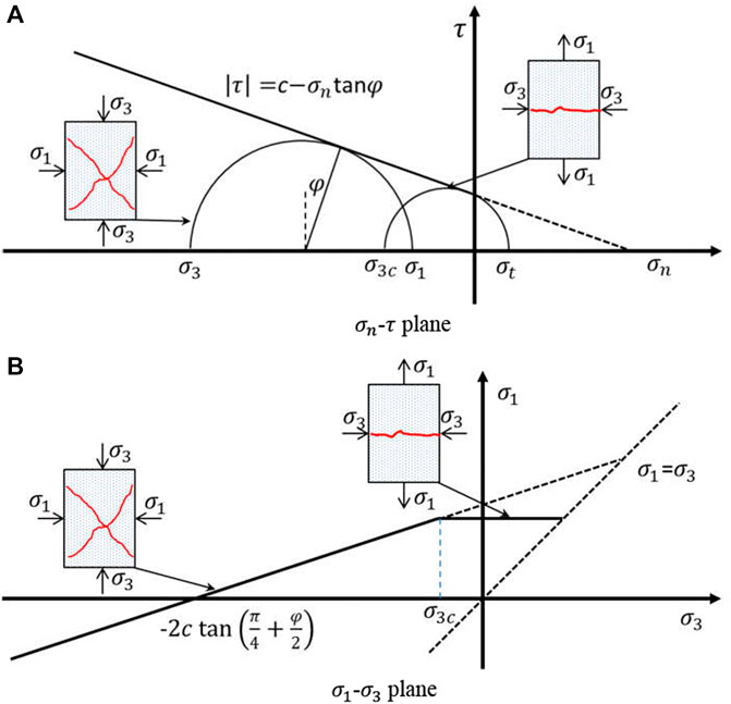
FIGURE 3.
Herein,
According to the Mohr–Coulomb criterion, if
If
Crack Tracking and Mathematical Element Reconstruction
Relative to other numerical calculation methods, the numerical manifold method uses two elements, namely, mathematical and physical elements, which are very simple to reconstruct in crack propagation.
The steps of reconstructing mathematical and physical elements in crack propagation are as follows:
(1) If the crack failure is caused by propagation, then propagate one physical element in each step. The physical element transforms into two physical elements after failure. The artificial joint technology used in this work retains some joints that have been cut to ensure the geometric accuracy of the joints in the simulation process. In the crack propagation simulation, simulate the physical element failure with and without an artificial joint.
If the physical element contains an artificial joint and the propagation crack is the same as the artificial crack, then transform the artificial joint into a propagation joint. If the propagation crack and artificial crack are on the same edge of the mathematical element, then change the coordinates of the artificial joint endpoints, transform the artificial joint into a propagation joint, and calculate the stress and node displacement of the physical elements related to the mathematical element according to the new coordinates (Figure 4). In any other case, consider that the physical element does not contain any artificial cracks.
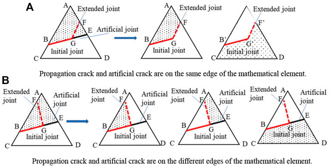
FIGURE 4. Physical element failure containing artificial joint. (A) Propagation crack and artificial crack are on the same edge of the mathematical element. (B) Propagation crack and artificial crack are on the different edges of the mathematical element.
If the physical element does not contain any artificial crack, then change the geometric properties of the original physical element, and increase those of the new physical element. Typical element failure is shown in Figure 5.
(2) Determine the mathematical element J corresponding to the physical element, and establish the mathematical covers
(3) Perform the joint connectivity judgement for the physical elements in
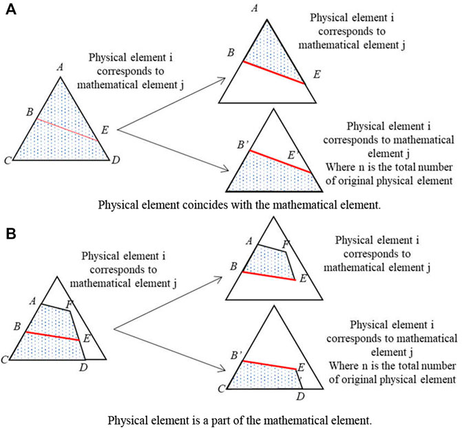
FIGURE 5. Typical failure of physical element. (A) Physical element coincides with the mathematical element. (B) Physical element is a part of the mathematical element.
This work should point out that in the process of single joint propagation failure, if the joint failure starts from the mathematical element boundary, then only the connectivity judgement for the two mathematical covers corresponding to the mathematical element boundary is performed. If the joint failure starts from the vertex of the mathematical element, then only the connectivity judgement for one mathematical cover corresponding to the vertex is performed. As for multi-joint failure, as a result of the coalescence between joints, connectivity judgement is performed for three mathematical covers (Figure 6). Therefore, even in the case of multi-joint propagation, crack propagation only results in an increase in three mathematical covers at most.
(4) For the newly generated physical element, recalculate the stress and displacement. Given the conservation of mass, all geometric and physical–mechanical information in the newly generated mathematical cover is the same as that in the initial cover. According to the principle of coalescence, correlate the physical element and the mathematical element near the crack tip with the mathematical cover, and then input the newly generated physical element and mathematical cover into the calculation model.
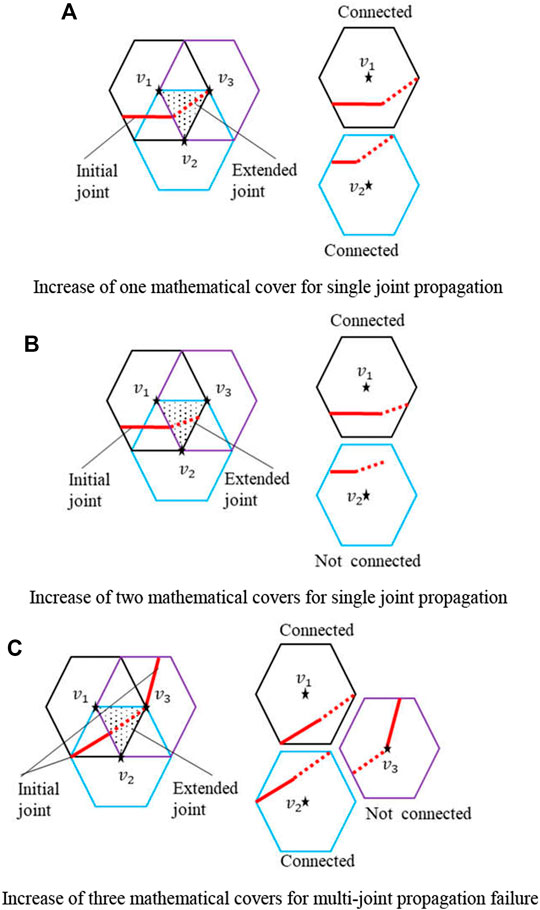
FIGURE 6. Typical connectivity judgement of mathematical elements. (A) Increase of one mathematical cover for single joint propagation. (B) Increase of two mathematical covers for single joint propagation. (C) Increase of three mathematical covers for multi-joint propagation failure.
Verification of Failure Simulation Programme of Jointed Rock Mass
Verification of Uniaxial Compression Test
The uniaxial compression test is the most frequently used method to study the failure process of jointed rock masses [5,12,13,19–22], and it has generated numerous results. Although the occurrence and mechanism of joint failure and coalescence have been broadly disputed, the distribution mode of typical structural planes is the same as the failure mode in the previously described results. Therefore, this section verifies the rationality of the programme based on the numerical model of a typical structural plane distribution.
[19] summarised the joint failure modes with different values of
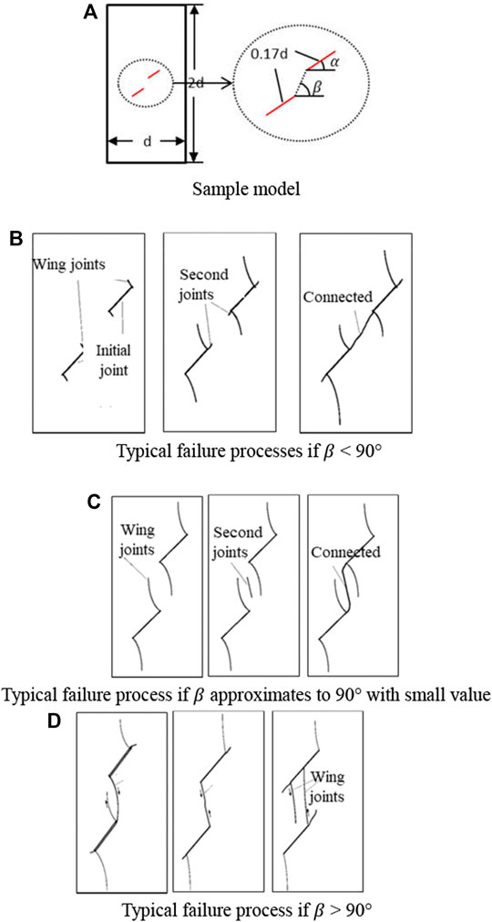
FIGURE 7. Typical failure mode of uniaxial compression. (A) Sample model. (B) Typical failure processes if β < 90°. (C) Typical failure process if β approximates to 90° with small value. (D) Typical failure process if β > 90°.
The basic parameters of the geometric dimensions of the calculation example for verification are shown in Table 1. Through the simulation analysis of the three models with rock bridge inclination angles
Figure 8 shows the failure process of numerical specimen with inclination angle
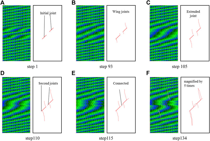
FIGURE 8. The failure process of numerical specimen with inclination angle

FIGURE 9. Comparison between final failure mode and typical failure mode. (A) β = 45°, (B) β = 90°, and (C) β = 120°.
Verification of Direct Shear Test
Figure 10 shows the comparison of failure modes based on different structural plane distribution modes under a normal stress of 1.0 MPa. The comparison of the stress–strain process curves is shown in Figure 11, and the comparison of the comprehensive shear strength and test results is shown in Table 2. The results reveal the following:
(1) The same failure mode of jointed rock masses is obtained from the numerical simulation test. The proposed method can effectively simulate the failure process and final failure mode of the jointed rock mass.
(2) Two differences are identified between the stress–strain curve recorded by the numerical simulation programme and the actual results. First, because the numerical sample material is a completely linear elastic material, the stress–strain curve directly enters the linear elastic stage rather than the early compaction stage. Second, because the numerical simulation programme does not define the crack growth rate, the stress intensity factor and fracture toughness are compared to judge whether the joint propagates. After each crack propagation, the failure of a physical element occurs. As a result of different failure speeds, the corresponding curves are different.
(3) The comprehensive shear strength of a rock mass obtained by the numerical simulation programme is in good agreement with the test results, and the error does not exceed 5%.
(4) At present, the crack growth rate is determined on the basis of the propagation length of the joint and the characteristics of the object without considering the spatial distribution of the joint. Each failure runs through a physical element. Due to the different failure speed, there is a certain difference between the stress-strain curve obtained from the numerical test and the measured stress-strain curve (Figure 11). Therefore, the instantaneous brittle failure of a rock mass determined by the spatial distribution of structural planes is not simulated herein and will be explored in future work.
(5) Nevertheless, for practical engineering applications and engineering mechanical properties of jointed rock masses, the current simulation programme for the failure process of jointed rock masses can effectively simulate the failure process and final failure mode of jointed rock masses and obtain rational peak values and residual shear strength values, which meet the requirements of engineering applications.
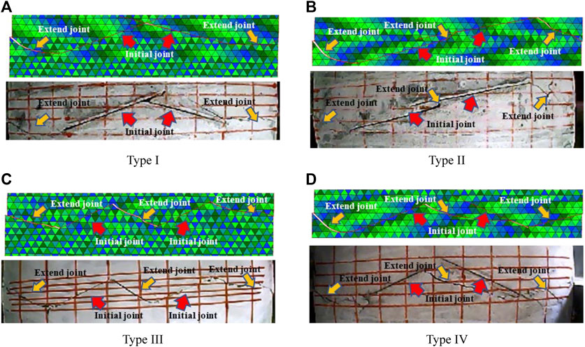
FIGURE 10. Comparison between results of numerical simulation test and failure results of indoor direct shear test. (A) Type I, (B) Type II, (C) Type III, and (D) Type IV.
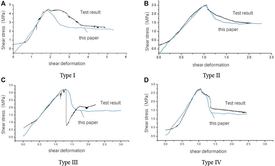
FIGURE 11. Comparison of stress–strain process curves. (A) Type I, (B) Type II, (C) Type III, and (D) Type IV.

TABLE 2. Comparison between comprehensive shear strength of numerical simulation test and test results.
Conclusion
(1) This work introduces a virtual joint technology and improves the algorithm of the numerical manifold element generation of jointed rock masses so that the distribution lengths of joints do not change due to mass search. These achievements improve the calculation accuracy of the numerical manifold method.
(2) According to the concept of stress intensity factor in fracture mechanics, this study uses the contour integral method to calculate the stress intensity factor at the crack tip and solves the problems of reconstruction and stress transmission of mathematical and physical elements in the failure process of jointed rock masses. It also develops a simulation programme for the whole process of deformation, failure and propagation of jointed rock masses.
(3) This work compares the patterns, stress–strain response curves and comprehensive shear strengths in uniaxial and direct shear tests. The results show that the simulation programme for the failure process of jointed rock masses can effectively simulate the failure process and final failure form of jointed rock masses and obtain rational peak values and residual shear strength values, which meet the requirements of engineering applications.
Data Availability Statement
The raw data supporting the conclusions of this article will be made available by the authors, without undue reservation.
Author Contributions
All authors listed have made a substantial, direct, and intellectual contribution to the work and approved it for publication.
Funding
This research was financially supported by the National Key R&D Program of China (No. 2018YFC0407000), the National Natural Science Foundation of China (No. 51809289, U1965204) and the IWHR Research & Development Support Program (No. GE0199A082021, GE110145B0022021). Research Project of China Three Gorges Corporation (Contract No. JG/19055J).
Conflict of Interest
JJ was employed by the company Huaneng Lancang River Hydropower Co., Ltd., and GC was employed by the company China Power Construction Group Kunming Survey, Design and Research Institute Co., Ltd.
The remaining authors declare that the research was conducted in the absence of any commercial or financial relationships that could be construed as a potential conflict of interest.
Publisher’s Note
All claims expressed in this article are solely those of the authors and do not necessarily represent those of their affiliated organizations, or those of the publisher, the editors, and the reviewers. Any product that may be evaluated in this article, or claim that may be made by its manufacturer, is not guaranteed or endorsed by the publisher.
References
1. Greenwood JA, Williamson J. Contact of Nominally Flat Surfaces. Proc R Soc Lond (1966) 295(1442):300–19. 10.1098/rspa.1966.0242.
2. Goodman RE, Taylor RL, Brekke TLA. A Model for the Mechanics of Jointed Rock. ASCE Soil Mech Found Division J (1968) 99(5):637–59. doi:10.1061/jsfeaq.0001133
3. Lajtai EZ. Shear Strength of Weakness Planes in Rock. Int J Rock Mech Mining Sci Geomechanics Abstr (1969) 6(5):499–515. IN497,509-IN498,515. doi:10.1016/0148-9062(69)90016-3
4. Lajtai EZ. A Theoretical and Experimental Evaluation of the Griffith Theory of Brittle Fracture. Tectonophysics (1971) 11(2):129–56. doi:10.1016/0040-1951(71)90060-6
5. Barton N. Review of a New Shear-Strength Criterion for Rock Joints. Eng Geology (1973) 7(4):287–332. doi:10.1016/0013-7952(73)90013-6
6. Bandis SC, Lumsden AC, Barton NR. Fundamentals of Rock Joint Deformation. Int J Rock Mech Mining Sci Geomechanics Abstr (1983) 20(6):249–68. doi:10.1016/0148-9062(83)90595-8
7. Gens A, Carol I, Alonso E. An Interface Element Formulation for the Analysis of Soil-Reinforcement Interaction. Comput Geotechnics (1989) 7(1-2):133–51. doi:10.1016/0266-352x(89)90011-6
8. Lin H, Lei D, Yong R, Jiang C, Du S. Analytical and Numerical Analysis for Frost Heaving Stress Distribution within Rock Joints under Freezing and Thawing Cycles. Environ Earth Sci (2020) 79(12). doi:10.1007/s12665-020-09051-x
9. Ge Y, Xie Z, Tang H, Du B, Cao B. Determination of the Shear Failure Areas of Rock Joints Using a Laser Scanning Technique and Artificial Intelligence Algorithms. Eng Geology (2021) 293:106320. doi:10.1016/j.enggeo.2021.106320
10. Shi GH. Manifold Method of Material Analysis. In: Transactions of the 9^ Army Conference On Applied Mathematics and Computing, Minesota, Minneaplolis (1991). p. 1–26.
11. Shi GH. Modeling Rock Joint and Bocks by Manifold Method. In: Proceedings of the 33th US rock mechanics symposium, San Ta Fe, New Mexico (1992).
12. Ma GW, An XM, Zhang HH, Li LX. Modeling Complex Crack Problems Using the Numerical Manifold Method. Int J Fract (2009) 156(1):21–35. doi:10.1007/s10704-009-9342-7
13. Bahaaddini M, Sharrock G, Hebblewhite BK. Numerical Direct Shear Tests to Model the Shear Behaviour of Rock Joints. Comput Geotechnics (2013) 51(jun):101–15. doi:10.1016/j.compgeo.2013.02.003
14. Ge Y, Xie Z, Tang H, Chen H, Lin Z, Du B. Determination of Shear Failure Regions of Rock Joints Based on point Clouds and Image Segmentation. Eng Geology (2019) 260:105250. doi:10.1016/j.enggeo.2019.105250
15. Ban L, Du W, Qi C. Stability Analysis of Anchored Slopes Based on a Peak Shear-Strength Criterion of Rock Joints. Environ Earth Sci (2020) 79(10):1–10. doi:10.1007/s12665-020-08961-0
16. Ju M, Li J, Li J, Zhao J. Loading Rate Effects on Anisotropy and Crack Propagation of Weak Bedding Plane-Rich Rocks. Eng Fracture Mech (2020) 230:106983. doi:10.1016/j.engfracmech.2020.106983
17. Griffith AA. The Phenomena of Rupture and Flow in Solids. Philos Trans R Soc A Math Phys Eng Sci (1920) A221(4):163–98. doi:10.1098/rsta.1921.0006
18. Muskhelishvili NI. Some Basic Problems of the Mathematical Theory of Elasticity. The Am Math Monthly (1967) 74(6):752. doi:10.1007/978-94-017-3034-1
19. Shen B, Stephansson BS. Numerical Analysis of Mixed Mode I and Mode II Fracture Propagation. Int J Rock Mech Mining Sci Geomechanics Abstr (1993) 30(7):861–7. doi:10.1016/0148-9062(93)90037-e
20. Chau KT, Wong RHC. Uniaxial Compressive Strength and point Load Strength of Rocks. Int J Rock Mech Mining Sci Geomechanics Abstr (1996) 33(2):183–8. doi:10.1016/0148-9062(95)00056-9
21. Bobet A, Einstein HH. Fracture Coalescence in Rock-type Materials under Uniaxial and Biaxial Compression. Int J Rock Mech Mining Sci (1998) 35(7):863–88. doi:10.1016/s0148-9062(98)00005-9
22. Wong R, Guo Y, Li LY, Chau KT, Li SC. Anti-Wing Crack Growth from Surface Flaw in Real Rock under Uniaxial Compression, Fracture of Nano and Engineering Materials and Structures. In: Proceedings of the 16th European Conference of Fracture (ECF16); Alexandroupolis, Greece; 3-7 July 2006 (2006), p. 825–826 .
Keywords: jointed rock mass, numerical manifold method, stress intensity factor, deformation and failure process, artificial joint technology
Citation: Lin X-C, Zhang Q, Jin J, Chen G and Li J-H (2022) Simulation of Deformation Process Failure of Jointed Rock Masses Based on the Numerical Manifold Method. Front. Phys. 9:828504. doi: 10.3389/fphy.2021.828504
Received: 03 December 2021; Accepted: 20 December 2021;
Published: 13 January 2022.
Edited by:
Chun Zhu, Hohai University, ChinaReviewed by:
Guoyong Duan, China Three Gorges University, ChinaXiaohu Zhang, Guizhou University of Engineering Science, China
Copyright © 2022 Lin, Zhang, Jin, Chen and Li. This is an open-access article distributed under the terms of the Creative Commons Attribution License (CC BY). The use, distribution or reproduction in other forums is permitted, provided the original author(s) and the copyright owner(s) are credited and that the original publication in this journal is cited, in accordance with accepted academic practice. No use, distribution or reproduction is permitted which does not comply with these terms.
*Correspondence: Qiang Zhang, emhhbmdxQGl3aHIuY29t
†ORCID: Qiang Zhang, orcid.org/0000-0002-6173-7706
 Xing-Chao Lin
 Qiang Zhang
 Jiufeng Jin2