 Saripalli Bhanu Prakash
 Gagan Singh
 Sonika Singh
- Department of Electrical and Electronics & Communication Engineering, DIT University, Dehradun, India
For a quick and consistent photovoltaic (PV) module design, an effective, fast, and exact simulator is crucial to examine the performance of the photovoltaic cell under partial or quick variation of temperature and irradiance. The most prevalent modeling strategy is to apply an equivalent (electrical) circuit that encompasses together non-linear and linear mechanisms. This work proposes the modeling and analysis for a four-parameter two-diode photovoltaic cell model based on the manufacturer's data-sheet. The proposed model needs only four parameters compared to the previously developed seven-parameter two-diode model to reduce the computational complexity. To develop a specific model of photovoltaic cells, the fundamental requirement is the data of temperature and irradiance. The variation of these variables totally affects the output constraints like current, voltage, and power. Thus, it is substantial to design a precise model of the photovoltaic cell module with a reduced computation period. The two-diode photovoltaic module with four constraints is identified to be more accurate and have improved performance compared to a one-diode model particularly at lower irradiance. To confirm the accuracy of the proposed model the method is applied on two different photovoltaic modules. The proposed model and modeling method are helpful for power electronic designers who require a fast, accurate, simple, and easy to implement method for use in photovoltaic system simulation. The electrical equivalent circuit and standard equations of photovoltaic cells are analyzed and the proposed two-diode model is simulated using MATLAB/Simulink software and validated for poly-crystalline and mono-crystalline solar cells under standard test conditions.
Introduction
In recent years, several models have been developed including the single-diode RS model, RP model, and double-diode and triple-diode model [1–3]. The most modest scheme is a one-diode PV model (ideal case) as it involves only three variables: current at short circuit, voltage at open circuit, and diode ideality factor. The enhanced type of the model includes the insertion of series resistance Rs to the equivalent circuit [4]. While this model suffers from inconsistencies with the change in the temperature values as it does not considered the voltage temperature coefficient. The upgraded version is the RP model by the insertion of a shunt resistor to the equivalent circuit [5]. Though this model has improved accuracy, with the insertion of RP the computational parameters are increased to five which leads to more computation time.
In general, most of the constructors only provide data about constraints like voltage at open circuit (Vo), current at short circuit (ISC), peak or maximum power (Pmpp), current at Pmpp (Impp), and voltage at Pmpp (Vmpp) at standard operating conditions and inappropriately these data are far away from what is essential for modeling because a PV cell is used to functioning at various ecological conditions. The non-linear performance of current-voltage characteristics requires the alteration of constraints by using the manufacturer data sheet [6, 7].
So far, many researchers have developed a single-diode model by making an assumption that nonappearance of recombination loss occurs in the depletion layer. In reality, it is not possible to satisfactorily model by using a single diode. Consideration of this loss results in a more exact model, identified as the two-diode model [8]. But, with the insertion of the extra diode it increases the constraints to seven and the new constraints include reverse saturation current IDS2 and ideality factor C2 of the second diode. The main task is now to evaluate the values of the model constraints while keeping a realistic computational energy. The key knowledge of this paper, to develop a detailed model of a two-diode PV cell module, is by simplifying the current equation and thereby reducing the constraints to four. The precision of this PV model is confirmed by two different solar PV cells from the constructor information sheet and behavior performance is compared with a one-diode RSH model. This enhanced model can be useful for researchers who work on the precise modeling of photovoltaic (PV) modules.
Fundamentals and Circuit Model of Photovoltaic Cells
Effective Principle of Photovoltaic Cells
A basic structure of a typical photovoltaic cell is represented in Figure 1. A photovoltaic cell essentially consists of two films doped in a different way and behaves as a semiconductor diode through its p-n junction, which is exposed to incident light [9]. When the photovoltaic cell is exposed to this light, electron-hole pairs are generated which initiates the flow of the electric current if the circuit is closed from cathode (N type) to anode (P type).
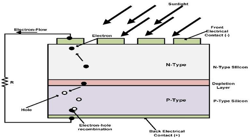
Figure 1. Structure of a photovoltaic cell [9].
By this convention, the electric current direction is always chosen with reference to the direction of movement of positive charges. Consequently, the direction of current in the load circuit is shown from a positive to negative terminal.
Electrical Equivalent Circuit of One-Diode Photovoltaic Cell Model
The one-diode model with a series and parallel resistor is represented in Figure 2 [3]. For practical reasons, we cannot neglect the RSE and RSH resistor in photovoltaic cell modeling. With the addition of these resistors, the constraints are now increased to five which also lengthens the computation time. This model is the most popular due its ease, accuracy, and easy of implementation. Despite of its advantages, the model's accuracy will worsen at lower irradiance [10].
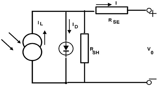
Figure 2. Equivalent circuit model: one-diode photovoltaic (PV) model [3].
Modeling of a Photovoltaic Cell and Determination of Constraints
Modeling of a Two-Diode Photovoltaic Cell
The two-diode PV model is represented in Figure 3 [2]. Obviously, two more new constraints now need to be considered: the reverse saturation diode current IDS2 and ideality factor C2. The current IDS2 compensates for the consequence of recombination loss in the depletion area [11].

Figure 3. Equivalent circuit model: two-diode photovoltaic (PV) model [2].
By applying KVL to Figure 3, we get the expression for current I:
IL is the light or photo current, ID1 and ID2 is the current through diode 1 and diode 2, ISH is the current through the shunt resistor = , RSE and RSH are series and shunt resistances, V0 is applied voltage across diode, and I is module output current [12].
Currents through diodes 1 and 2 are given by
IDs1 and IDs2 are reverse saturation diode current, C1 and C2 are the diode ideality factor of 1 and 2, NSE is series-connected PV cells, VT is thermal voltage = , VT is approximately 25.856 mV at 300 Kelvin, q is (1.602 X 10⁻¹⁹), C is electron charge, K – (1.38 X 10⁻²³) is a Boltzmann constant, and TAc is the cell's absolute temperature in Kelvin.
Light or photo current [9] is given by
Gir – irradiance in , GSC – irradiance at the standard test condition (STC) = 1,000 , TAc = TAc − ΔTAc,ref (Kelvin), TAc,ref − (25 + 273 = 298 Kelvin), ISC is the cell's short circuit current at STC (25°), and γSC is the current temperature coefficient (A/K).
where γV – voltage temperature coefficient (V/K).
In making the model simple for analysis, the seven constraints are reduced to four by assuming the IDS = IDS1 = IDS2 and ) = 1 as described in [12] Therefore.
Determination of Photovoltaic Module Constraints
Owing to its complication in analysis and constraints estimation, the analysis and simulation of the PV cell in the two-diode model is not so simple. To make it easier to study the following assumptions are considered: the IDS = IDS1 = IDS2 and ) = 1. By inputting the temperature and irradiance in Equations (3) and (5), the light current and diode saturation currents are estimated by using the constructor datasheet. By setting the values of ideality factors C1 = 1 and C2 = 1.2 yields the best suitable outcomes in the current-voltage curve of the PV cell module. These alterations make the two-diode model into its simplified form and therefore attractive for PV system simulation. In general, the constructor gives data of current at short circuit (ISC), voltage at open circuit (Vo) and peak or maximum power (Pmpp). Now we will evaluate the current equation shown below for three conditions: current (ISC) at short circuit, voltage (Vo) at open circuit, and peak or maximum power (Pmpp) point condition.
At the short circuit condition
where, and
At the open circuit condition
From Equation (7)
where and
At the maximum power condition
From Equation (12)
where Pmpp is the peak or maximum power, Vmpp,STC is the voltage at Pmpp, and Impp,STC is the current at Pmpp, diode saturation currents at the maximum power condition is given by the relation as shown below:
Determination of RSE and RSH Constraints
Several analytical and numerical approaches [3, 6, 7, 9, 13–15] have been proposed in the literature to evaluate the constraints of one-diode and two-diode models. In this analysis the constraints RSE and RSH are estimated by the same method as described previously [9]. By using effective iteration process the value of RSE and RSH can be estimated with the help of Equation (10). The main takeaway is that the value of RSE and RSH are selected such that calculated power Pmpp must be equal to experimental power provided by the constructor data sheet Pmpp,STC. This iteration procedure initiates from RSE = 0 which must vary in directive until it matches the calculated maximum power of Pmpp,STC, and simultaneously RSH is calculated.
Simulation of Proposed Two-Diode Model
The complete sub-system group model of the proposed two-diode photovoltaic (PV) module is represented in Figure 4. By using Equations (2)–(5), detailed simulation models were developed in MATLAB/Simulink. The simulation block diagram of diode saturation current is represented in Figure 5, light current is represented in Figure 6, and module output current is represented in Figure 7. The component specifications of both mono-crystalline and poly-crystalline PV modules are shown in Table 1. Table 2 illustrates the determined values of the proposed two-diode model and Table 3 shows the constraints for the one-diode RSH model. Tables 4, 5 summarize the study of relative error of Pmpp, Vmpp, Impp, Vo, and ISC of both mono and poly-crystalline solar cells. The proposed two-diode model actually requires only four constraints because saturation current IDS1 = IDS2 = IDS whereas C1 = 1, C2 is chosen >1.2 and the value of p is recommended to be a value larger than 2.2 [12].
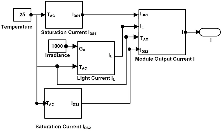
Figure 4. Complete sub-system model of proposed two-diode photovoltaic (PV) model.
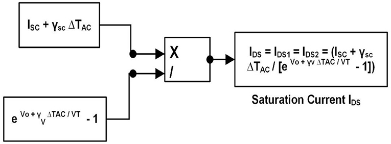
Figure 5. Saturation current (IDS) of proposed two-diode model.
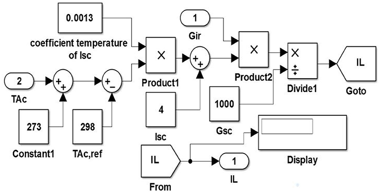
Figure 6. Light current (IL) of proposed two-diode model.
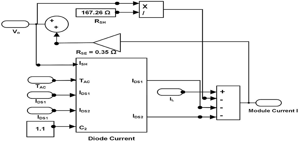
Figure 7. Module output current (I) of proposed two-diode model.
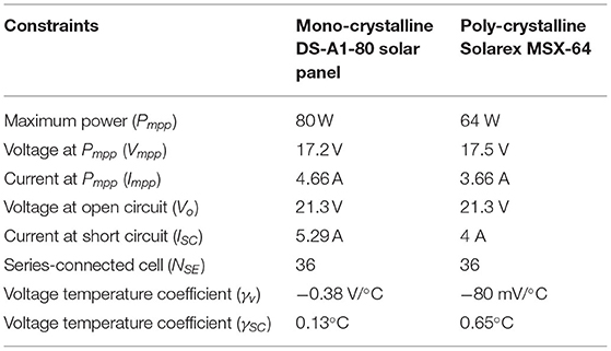
Table 1. Component specifications from constructor data sheet.
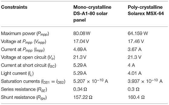
Table 2. Estimated values of proposed two-diode model.

Table 3. Estimated values of one-diode RSH model.
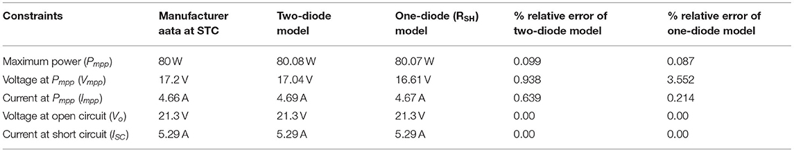
Table 4. Comparison of estimated values at maximum power (Pmpp) of the two-diode model and one-diode (RSH) model for a mono-crystalline (DS-A1-80) solar cell.
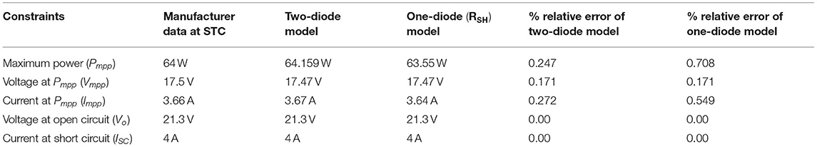
Table 5. Comparison of estimated values at maximum power (Pmpp) of the two-diode model and one-diode (RSH) model for a poly-crystalline solar cell (MSX-64).
Simulation Results and Discussion
The modeling technique characterized in this work is confirmed by measured constraints of certain photovoltaic (PV) cell modules. Two different PV modules; mono-crystalline DS-A1-801 and poly-crystalline MSX-642 are employed for verification. We can observe that the calculated values slightly deviate from the manufacturer data sheet value at STC. However, the poly-crystalline (MSX-64) cell exactly fits the manufacturer data for the proposed two-diode model. Figures 8, 9 characterize the power vs. voltage curve of RSH and the proposed two-diode model for mono-crystalline and poly-crystalline solar cells at STC. Comparative analysis of the current vs. voltage curve of RSH and the proposed two-diode model for the DS-A1-80 solar cell at various temperatures and irradiance levels are represented in Figures 10, 11. Comparative analysis of the current vs. voltage curve of RSH and proposed two-diode model for the MSX-64 solar cell at various temperatures and irradiance levels are represented in Figures 12, 13. From the results we can observe that both models exhibited the same performance at STC. However, the proposed two-diode model showed better performance compared to the RSH model precisely at lesser irradiance levels especially for open circuit voltage. The comparison of estimated values at maximum power (Pmpp) of the two-diode model and one-diode (RSH) model for mono-crystalline (DS-A1-80) and poly-crystalline (MSX-64) solar cells are shown in Tables 4, 5.
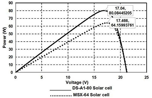
Figure 8. Power (W) vs. voltage (V) curve of proposed two-diode model for DS-A1-80 and MSX-64 at STC (25°C and 1,000 KW/m2).

Figure 9. Power (W) vs. voltage (V) curve of one-diode RSH for DS-A1-80 and MSX-64 at STC (25°C and 1,000 KW/m2).
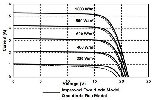
Figure 10. Comparative analysis of current (A) vs. voltage (V) curve for one-diode RSH and proposed two-diode model for DS-A1-80 with different irradiance points at STC (25°C).
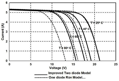
Figure 11. Comparative analysis of current (A) vs. voltage (V) curve for one-diode RSH and proposed two-diode model for DS-A1-80 with different temperature points at STC (1,000 KW/m2).

Figure 12. Comparative analysis of current (A) vs. voltage (V) curve for one-diode RSH and proposed two-diode model for MSX-64 with different irradiance points at STC (25°C).
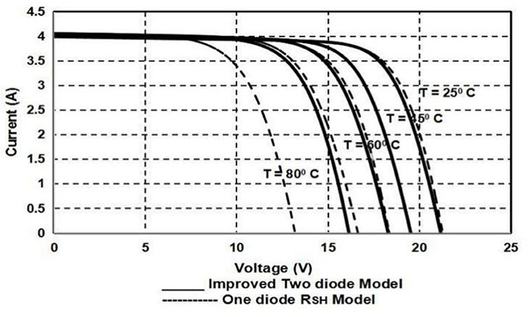
Figure 13. Comparative analysis of current (A) vs. voltage (V) curve for one-diode RSH and proposed two-diode model for MSX-64 with different temperature points at STC (1,000 KW/m2).
Conclusion
For a quick and consistent photovoltaic module design, an effective, fast, and exact simulator is crucial to examine the performance of the photovoltaic cell under a partial or quick variation of temperature and irradiance. The most prevalent modeling strategy is to apply an equivalent (electrical) circuit that encompasses both non-linear and linear mechanisms. In the proposed work, an improved typical two-diode system aimed at photovoltaic cell modules was developed. Distinct from past photovoltaic modules recommended by many researchers, the developed work only needed the calculation of four constraints. A modest and fast iterative technique was used to estimate RSE and RSH resistances. The accuracy of the developed model was examined by using experimental data provided by the constructors of two different photovoltaic cell modules. Its performable behavior was compared with one-diode RSH models. It was observed that the proposed two-diode model had improved performance specifically at open circuit voltage and short circuit current and maximum power point conditions irrespective of variations in temperature and irradiance. Specifically, it showed better performance and accuracy at lesser irradiance situations. The proposed model was validated for mono-crystalline and poly-crystalline solar cells under standard test conditions.
Data Availability Statement
The original contributions presented in the study are included in the article/supplementary material, further inquiries can be directed to the corresponding author/s.
Author Contributions
All authors listed have made a substantial, direct and intellectual contribution to the work, and approved it for publication.
Conflict of Interest
The authors declare that the research was conducted in the absence of any commercial or financial relationships that could be construed as a potential conflict of interest.
Publisher's Note
All claims expressed in this article are solely those of the authors and do not necessarily represent those of their affiliated organizations, or those of the publisher, the editors and the reviewers. Any product that may be evaluated in this article, or claim that may be made by its manufacturer, is not guaranteed or endorsed by the publisher.
Footnotes
1. ^Available online at: http://www.posharp.com/ds-a1-80-solar-panel-from-anji-dasol-solarenergysciencetechnology_p462201154d.aspx (accessed January 31, 2021).
2. ^Available online at: https://www.solarelectricsupply.com/media/custom/upload/Solarex-MSX64.pdf (accessed January 31, 2021).
References
1. Khanna V, Das BK, Bisht D, Singh PK. A three-diode model for industrial solar cells and estimation of solar cell parameters using PSO algorithm. Renew Energy. (2015) 78:105–13. doi: 10.1016/j.renene.2014.12.072
2. Shannan NM, Yahaya NZ, Singh B. Single-diode and two-diode model of PV modules: A comparison. In: IEEE International Conference on Gontrol System, Computing and Emerging (Penang). (2013). p. 210–4.
3. Lo Brano V, Orioli A, Ciulla G, Di Gangi A. An improved five-parameter model for photovoltaic modules. Solar Energy Mater Solar Cell. (2010) 94:1358–70. doi: 10.1016/j.solmat.2010.04.003
4. Chenni R, Makhlouf M, Kerbache T, Bouzid A. A Detailed modeling method for photovoltaic cells. Energy. (2007) 32:1724–30. doi: 10.1016/j.energy.2006.12.006
5. Sera D, Teodorescu R, Rodriguez P. PV panel model based on datasheet values. In: Proceedings of the IEEE International Symposium on Industrial Electronics (ISIE) (Vigo). (2007). p. 2392–6.
6. Singh P, Ravindra NM. Analysis of series and shunt resistance in silicon solar cells using single and double exponential models. Emerg Mater Res. (2011) 1:33–8. doi: 10.1680/emr.11.00008
7. AlRashidi MR, AlHajri MF, El-Naggar KM, Al-Othman AK. A new estimation approach for determining the I–V characteristics of solar cells. Solar Energy. (2011) 85:1543–50. doi: 10.1016/j.solener.2011.04.013
8. Chih-Tang S, Noyce RN, Shockley W. Carrier generation and recombination in p–n junctions and p–n junction characteristics. Proceedings of IRE, Vol. 90. (1957) 45:1228–43. doi: 10.1109/JRPROC.1957.278528
9. Villalva MG, Gazoli JR, Filho ER. Comprehensive approach to modeling and simulation of photovoltaic arrays. IEEE Transact Power Electron. (2009) 24:1198–208. doi: 10.1109/TPEL.2009.2013862
10. Salam Z, Ishaque K, Taheri H. An improved two-diode photovoltaic (PV) model for PV system. In: International Conference on Power Electronics, Drives and Energy Systems (PEDES) Power India (New Delhi). (2010). p. 1–5.
11. Mcintosh K, Pietro Altermatt P, Heiser G. Depletion-region recombination in silicon solar cells: when does m_DR = 2? In: Proceeding of the 16th European Photovoltaic Solar Energy Conference (Glasgow). (2000). p. 251–4.
12. Chin VJ, Salam Z, Ishaque K. Cell modelling and model parameters estimation techniques for photovoltaic simulator application: a review. Appl Energy. (2015) 154:500–19. doi: 10.1016/j.apenergy.2015.05.035
13. Alonso-Gracia MC, Ruiz JM, Chenlo F. Experimental study of mismatch and shading effects in I-V characteristics of a PV module. Solar Energy Mater Solar Cells. (2006) 90:329–40. doi: 10.1016/j.solmat.2005.04.022
14. Hejri M, Mokhtari H, Azizian MR, Ghandhari M, Söder L. On the parameter extraction of five parameter double-diode model of photovoltaic cell and modules. IEEE J Photovolt Cells. (2014) 4:915–23. doi: 10.1109/JPHOTOV.2014.2307161
Keywords: one-diode photovoltaic model, two-diode photovoltaic model, poly-crystalline solar cell, circuit constraints, mono-crystalline solar cell
Citation: Prakash SB, Singh G and Singh S (2021) Modeling and Performance Analysis of Simplified Two-Diode Model of Photovoltaic Cells. Front. Phys. 9:690588. doi: 10.3389/fphy.2021.690588
Received: 03 April 2021; Accepted: 15 April 2021;
Published: 25 October 2021.
Edited by:
Carlos Marques, University of Aveiro, PortugalReviewed by:
Rahul Kumar Gangwar, Peking University, ChinaDharmendra Kumar, Madan Mohan Malaviya University of Technology, India
Copyright © 2021 Prakash, Singh and Singh. This is an open-access article distributed under the terms of the Creative Commons Attribution License (CC BY). The use, distribution or reproduction in other forums is permitted, provided the original author(s) and the copyright owner(s) are credited and that the original publication in this journal is cited, in accordance with accepted academic practice. No use, distribution or reproduction is permitted which does not comply with these terms.
*Correspondence: Saripalli Bhanu Prakash, c2IucHJha2FzaEBkaXR1bml2ZXJzaXR5LmVkdS5pbg==