
94% of researchers rate our articles as excellent or good
Learn more about the work of our research integrity team to safeguard the quality of each article we publish.
Find out more
MINI REVIEW article
Front. Phys., 03 March 2021
Sec. Medical Physics and Imaging
Volume 9 - 2021 | https://doi.org/10.3389/fphy.2021.632056
This article is part of the Research TopicApplications of Cherenkov and Radioluminescence Imaging to Medicine and BiologyView all 7 articles
 R. Michael van Dam1,2*†Arion F. Chatziioannou1,2†
Over the past several years there has been an explosion of interest in exploiting Cerenkov radiation to enable in vivo and intraoperative optical imaging of subjects injected with trace amounts of radiopharmaceuticals. At the same time, Cerenkov luminescence imaging (CLI) also has been serving as a critical tool in radiochemistry, especially for the development of novel microfluidic devices for producing radiopharmaceuticals. By enabling microfluidic processes to be monitored non-destructively in situ, CLI has made it possible to literally watch the activity distribution as the synthesis occurs, and to quantitatively measure activity propagation and losses at each step of synthesis, paving the way for significant strides forward in performance and robustness of those devices. In some cases, CLI has enabled detection and resolution of unexpected problems not observable via standard optical methods. CLI is also being used in analytical radiochemistry to increase the reliability of radio-thin layer chromatography (radio-TLC) assays. Rapid and high-resolution Cerenkov imaging of radio-TLC plates enables detection of issues in the spotting or separation process, improves chromatographic resolution (and/or allows reduced separation distance and time), and enables increased throughput by allowing multiple samples to be spotted side-by-side on a single TLC plate for parallel separation and readout. In combination with new multi-reaction microfluidic chips, this is creating a new possibility for high-throughput optimization in radiochemistry. In this mini review, we provide an overview of the role that CLI has played to date in the radiochemistry side of radiopharmaceuticals.
The use of Cerenkov luminescence imaging (CLI) in the field of molecular imaging began with the realization that charged particles emitted by F-18 and other positron emitting sources have enough energy to produce Cerenkov light as they travel through matter [1–4]. If this light can be detected, then images of the spatial and temporal distribution of radiolabeled probes can be obtained non-destructively [1]. This realization led to a flurry of new applications including in vivo CLI in small animals or patients (reviewed in [5–15]), new methods for visualization of radioactivity distribution in microscale devices used for radiopharmaceutical production, and alternative methods for readout of radio-thin layer chromatography (radio-TLC) plates. This mini-review attempts to provide the first comprehensive summary of applications in these latter two areas of radiopharmaceutical production and analysis. CLI of microfluidic devices has enabled monitoring of microfluidic radiopharmaceutical synthesis in situ. Due to the well-defined and planar geometry of microfluidic chips, quantitative region-of-interest (ROI) analysis and detailed characterization of radiochemistry processes over time is possible, facilitating troubleshooting and optimization. CLI is also gaining traction in the determination of reaction yields or radiochemical purity of radiopharmaceuticals by offering some improvements in readout and the ability to significantly increase analysis throughput.
Over the past ∼15 years there has been increasing interest in microscale technologies for synthesizing radiopharmaceuticals due to many advantages over conventional methods, including shorter reaction times, reduced consumption of expensive reagents, high molar activity of small batches, cleaner reactions (enabling simpler and faster purification), and dramatic reductions in shielded space requirements due to compact size of equipment [16–19]. In this section we discuss several of these technologies where CLI has played an important role in their development.
Some of the earliest microfluidic devices capable of performing multi-step syntheses of radiopharmaceuticals were fabricated from polydimethylsiloxane (PDMS), a transparent elastomer widely used in microfluidics due to the relatively simple fabrication process and ability to easily integrate microvalves for fluid manipulation. Typically the reaction fluids are manipulated within a planar network of channels, adjacent to a second planar network of valve control channels that can be pressurized to mediate reagent delivery and close the reaction chamber during heating. In a proof-of-concept paper, Lee et al. reported a PDMS device with an integrated microscale ion-exchange cartridge and 40 nL ring-shaped reactor, and demonstrated the concentration of [18F]fluoride and synthesis of small quantities (∼7 MBq) of [18F]FDG [20]. A later report by Elizarov et al. showed, using a larger reactor volume (5 µl coin-shaped chamber), synthesis of >100 MBq of [18F]FDG [21]. However, these devices exhibited significant activity losses (up to 90%) and unreliable operation, postulated to be caused by incompatibilities between PDMS and [18F]fluoride.
A CLI setup was constructed to monitor the radioactivity distribution within the chip in situ [1, 2]. The chip was mounted inside a light-tight chamber on a temperature-controlled platform and connected to reagent inlets and microvalve control lines. Images were obtained with a cooled CCD camera and were subjected to dark current subtraction, flat field correction, and median filtering (to eliminate spurious bright pixels due to direct gamma or cosmic ray interactions with the sensor). Calibration was performed by filling a channel with aqueous [18F]FDG solution to relate Cerenkov signal intensity to radioactivity per unit area. For 5 min acquisitions, the minimum detectable activity was found to be 7.0 kBq/mm2 and the resolution was found to be <200 µm [2] (Figure 1A). Brightfield images of the chip could be obtained at any time by illuminating the chamber.
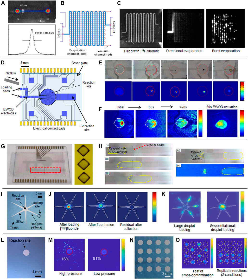
FIGURE 1. Use of Cerenkov imaging in the development of microfluidics for radiopharmaceutical production. (A) Top: Cerenkov image of microchannel containing [18F]FDG; Bottom: Line profile of signal intensity across the channel. Adapted from [2] by permission of IOP Publishing. © Institute of Physics and Engineering in Medicine. All rights reserved. (B) PDMS chip design for studying losses during [18F]fluoride drying. (C) Cerenkov images (without false coloring) after loading and sealing the chamber, and two possible patterns of radioactivity distribution after solvent evaporation (“directional” and “burst”). Adapted from [22]. (D) Diagram of EWOD radiosynthesis chip. (E) Optical (top row) and Cerenkov (bottom row) images after key steps in the synthesis of [18F]FDG. (D,E) adapted from [34]. (F) Cerenkov images of radioactivity distribution in EWOD chip reaction site after a droplet of precursor solution was added to dried [18F]fluoride residue. Left 3 images show time sequence during passive diffusion at room temperature. Right image shows distribution after 30s of active mixing using electrodes. Adapted from [35] with permission from the Royal Society of Chemistry. (G) EWOD chip with integrated filter for alumina bead-based scavenging of unreacted [18F]fluoride. (H) Optical images of chip at key steps during the purification process and Cerenkov image of the retained beads and purified droplet in the final state. (G,H) adapted, with permission, from [40], © IEEE. (I) Teflon-silicon chip for droplet radiochemistry based on passive transport. (J) Successive Cerenkov images of the chip after key steps in the synthesis of [18F]Fallypride. (I,J) adapted from [41] with permission from the Royal Society of Chemistry. (K) Cerenkov images of the chip after loading and drying 25 µl of concentrated [18F]fluoride all at once (left) or as a series of 0.5 µl droplets (right). Adapted from [42] with permission from the Royal Society of Chemistry. (L) Simplified Teflon-silicon chip where chip is rotated under dispensers to deliver reagents on demand. (M) Cerenkov images of chip after collection of crude product showing how the reagent delivery at excessive pressure has caused splashing (left) that is not evident at lower delivery pressure (right). (L,M) adapted from [43] with permission from the Royal Society of Chemistry. (N) High-throughput chip containing 4 × 4 array of reaction sites. (O) Cerenkov images after a cross-contamination study (left) and after the collection step after performing 8 reactions under one set of reaction conditions and another 8 reactions under different conditions (right). (N,O) adapted from [44] with permission from the Royal Society of Chemistry.
To study the initial steps of [18F]FDG synthesis, a PDMS chip was designed with a 3.3 µl reactor implemented as a serpentine channel (Figure 1B). An adjacent chip layer contained a perpendicular serpentine channel to which vacuum could be applied to remove solvent vapor passing through the intervening thin layer of PDMS. The distribution of radioactivity within the chip was imaged after: 1) loading [18F]fluoride and phase transfer catalyst solution into the reactor and sealing the chamber with microvalves; 2) heating the chip to evaporate solvent, and 3) flushing the dried radioisotope complex out of the chip [22]. Initial experiments at low activity levels identified two very different radioactivity distributions after the second step: either all activity accumulated at one end of the channel (“directional” pattern), or the activity was distributed in small irregular spots along the full channel (“burst” pattern) [22] (Figure 1C), something that had not been noticed under brightfield illumination. The overall activity loss from the chip, and the amount of residual activity stuck in the chip after flushing were quantified from the images and found to be related to the duration of heating the chip [22, 23]. Since the “directional” pattern could lead to chip failures (microvalves stuck in the closed position or channel clogging), and also required more time for solvent evaporation, the “burst” pattern was more desirable. A new PDMS chip was designed with an additional array of microvalves that subdivide the fluid in the reaction chamber during drying, ensuring activity remained distributed along the full channel similar to the burst pattern [24]. With this change, Cerenkov measurements showed that [18F]fluoride could be efficiently and reliably dried with <15% activity loss and <5% residual activity [24].
Additional PDMS chips have been reported in the field of radiochemistry, including the development of integrated resins for [18F]fluoride trapping and release [25, 26], synthesis of [18F]Fallypride [27] and [68Ga]Ga-PSMA-11 [28], radiolabeling of peptides with Cu-64 and Ga-68 [29, 30], and preparation of 89Zr-labeled antibodies [31]. Cerenkov imaging could potentially provide insights into these other devices. For example, Liu et al. designed a reaction optimization chip to compare labeling yield for different ratio mixtures of [18F]SFB, pH buffer, and a protein [32, 33], and a Cerenkov imaging study highlighted the need for mitigation of radioactivity adsorption on the surface of these chips during operation [2].
Cerenkov imaging has also been critical in the development and optimization of other types of microfluidic radiochemistry chips including electro-wetting-on-dielectric (EWOD). These devices consist of two planar glass substrates separated by a small gap (typically ∼150 µm) between which reagent droplets are sandwiched. The substrates contain thin patterned layers of transparent electrode material (e.g., indium tin oxide), dielectric material (e.g., silicon nitride), and hydrophobic material (e.g., Teflon AF), and reagents are transported as droplets by sequentially applying voltages along pathways of droplet-sized electrodes. Using an EWOD chip with a ∼17 µl central heated reaction zone (Figure 1D), Keng et al. reported the synthesis of up to 26 MBq of [18F]FDG [34]. Qualitative analysis via Cerenkov imaging revealed important details about the synthesis process: there was negligible radioactivity residue along droplet pathways; the activity became concentrated in a small spot rather than a wide distribution when performing solvent evaporation, and radioactivity remained confined to the reaction zone afterward, indicating absence of splattering or volatilization of activity during reaction steps (Figure 1E).
Imaging was performed with a second-generation setup that permitted shielding of the Cerenkov camera chip from the source, eliminating direct gamma ray hits and reducing spurious signal [35]. The influence of solvent index of refraction and deviations from nominal gap spacing between the bottom and top parts of the chip were investigated. Interestingly, the impact of solvent was small, indicating that the majority of Cerenkov light was generated in the inert glass material of the chip. Differences in gap spacing also had negligible impact, allowing fabrication tolerances. Taken together, these results implied that a single calibration factor would be sufficient for quantitative analysis. CLI-derived measurements of the total activity in the chip at different stages of the synthesis of [18F]FDG correlated well with dose calibrator measurements but were safer and more practical [35].
CLI was used to study the process of mixing the precursor solution with the ‘pellet’ of dried [18F]fluoride residue at the reaction site by observing the uniformity of Cerenkov signal within the droplet. It was found that mixing via actuation of reactor electrodes for just 30 s yielded similar uniformity as 7 min passive diffusion at room temperature, or 3 min heating at 60°C (Figure 1F). This information was impossible to visualize with the naked eye and could not be accurately estimated using dye-based methods. Another interesting and surprising finding was that the condensed vapor around the reaction site during fluorination was not only solvent, but contained ∼15% of the total radioactivity. Off-chip analysis showed that 32% of the condensate was the desired reaction intermediate and the remainder was unreacted [18F]fluoride. Based on this information, the synthesis process was altered to load an additional solvent droplet part-way through the reaction to rinse the condensate back into the reaction site. After these optimizations, the crude radiochemical yield increased from 50 ± 3% (n = 3) to 72 ± 13% (n = 5) [35].
Using insights learned with CLI, the syntheses of additional radiopharmaceuticals have been demonstrated in EWOD chips, including [18F]FLT [36], [18F]Fallypride [37], and [18F]SFB [38]. Furthermore, CLI was used to develop a method for evaporative concentration of [18F]fluoride to increase the synthesis scale [39].
As a proof-of-concept toward in situ purification on EWOD chips, Chen et al. integrated an array of pillars across the droplet pathway to act as a filter to assist in performing solid-phase extraction (Figure 1G) [40]. The crude reaction mixture (containing unreacted [18F]fluoride and [18F]Fallypride) was mixed with alumina microbeads, and then passed through the filter. The beads (with bound [18F]fluoride) were retained by the filter, while purified [18F]fallypride in solution (confirmed via radio-TLC analysis) was transported to the other side. CLI-derived measurements of the activity in the beads and solution on opposite sides of the filter (Figure 1H) matched closely the proportion of the two species in the original droplet as measured by radio-TLC, suggesting a novel mechanism to monitor radiochemical yields directly on chip.
A recent approach for droplet-based radiochemistry relies on simpler, patterned Teflon-coated silicon chips, with reactions performed in open droplets sitting atop the silicon surface. Due to varying droplet height as a function of volume and solvent, it is challenging to perform quantitative Cerenkov analysis with droplets; however, quantitative measurements of dried radioactive residues on chips was possible. Due to the lack of substantial Cerenkov-generating media in these chips, a transparent plate was placed over the chip during imaging (and removed afterward).
Reagent droplets are dispensed to the periphery of these chips, and tapered hydrophilic pathways spontaneously transport the droplets to the central reaction site (Figure 1I) [41]. Cerenkov imaging during the synthesis of [18F]FDG and [18F]Fallypride confirmed that negligible radioactive residue was left behind on reagent transport pathways, and that activity was confined to the reaction site during all steps (Figure 1J). Recently, this chip was combined with a radioisotope concentrator, enabling loading of 10 s of GBq of activity to a single droplet reaction [42]. To address the volume discrepancy between the radioisotope concentrator (∼25 µl) and reaction chip (∼2 µl), two loading methods were compared: loading the full volume at once and then evaporating a single large droplet, or loading 0.5 µl increments while heating the chip. Though direct observation showed no obvious differences, Cerenkov imaging of chips after drying (Figure 1K) revealed a significant problem with the resulting distribution of activity (i.e., mostly outside the reaction site) with the first method.
CLI revealed a strong dependence on solvent and droplet volume on activity distribution that made it difficult to optimize synthesis protocols [41], and thus the chip design was modified to eliminate the tapered pathways and retain only the central hydrophilic reaction site [43] (Figure 1L). Reagents were loaded by rotationally positioning the reaction site under different reagent dispensers. Cerenkov imaging was used to optimize reagent dispensing parameters to avoid splashing that was invisible to the naked eye (Figure 1M), and monitoring of the resulting synthesis showed more consistent droplet confinement to the reaction site for a wide range of solvents and reaction volumes.
Finally, CLI helped to measure the degree of cross-contamination between adjacent reaction sites during the development of novel high-throughput chips containing arrays of reaction sites for performing multiple syntheses in parallel for radiochemistry optimization or screening (Figures 1N,O) [44]. Furthermore, during application of these chips to synthesis optimization, CLI was also used for in situ measurement of the initial radioactivity loaded, and the residual activity left behind after collecting the crude product. These quantities cannot be measured for individual reaction sites using traditional measurement tools.
In addition to the use of CLI in visualizing microfluidic radiosynthesis process and devices, CLI has also been used to perform analysis of radiopharmaceuticals, particularly as a readout method for radio-thin layer chromatography (radio-TLC). This analytical technique is used to determine the radiochemical purity of radiopharmaceuticals or the reaction conversion during optimization of radiosynthesis processes. While radio-high-performance liquid chromatography (radio-HPLC) generally has higher separation resolution, radio-TLC is preferred in applications where there are only a few radioactive species, due to its simplicity and speed.
While various methods to read out TLC plates have been used in the past [45, 46], typically today, after spotting a sample and performing separation, radio-TLC plates are read out using a scanning radiation detector providing a one or two dimensional map of radioactivity distribution on the plate. With the advent of CLI, Park et al. reported a proof-of-concept study showing that a small-animal luminescence imaging system could be used to visualize Cerenkov emissions from a developed radio-TLC plate containing a mixture of 131I-labeled compounds [47]. CLI provided increased resolution (Figure 2A) and could be completed in 1 min, while exhibiting excellent agreement with a conventional radio-TLC scanner. Ha et al. showed the suitability for readout of several beta- and positron-emitting isotopes (P-32, I-124, I-131) by imaging TLC plates spotted with isotope solutions using a small-animal luminescence imaging system [48], and observed superior resolution compared to a 2D scanning detector (Figure 2B).
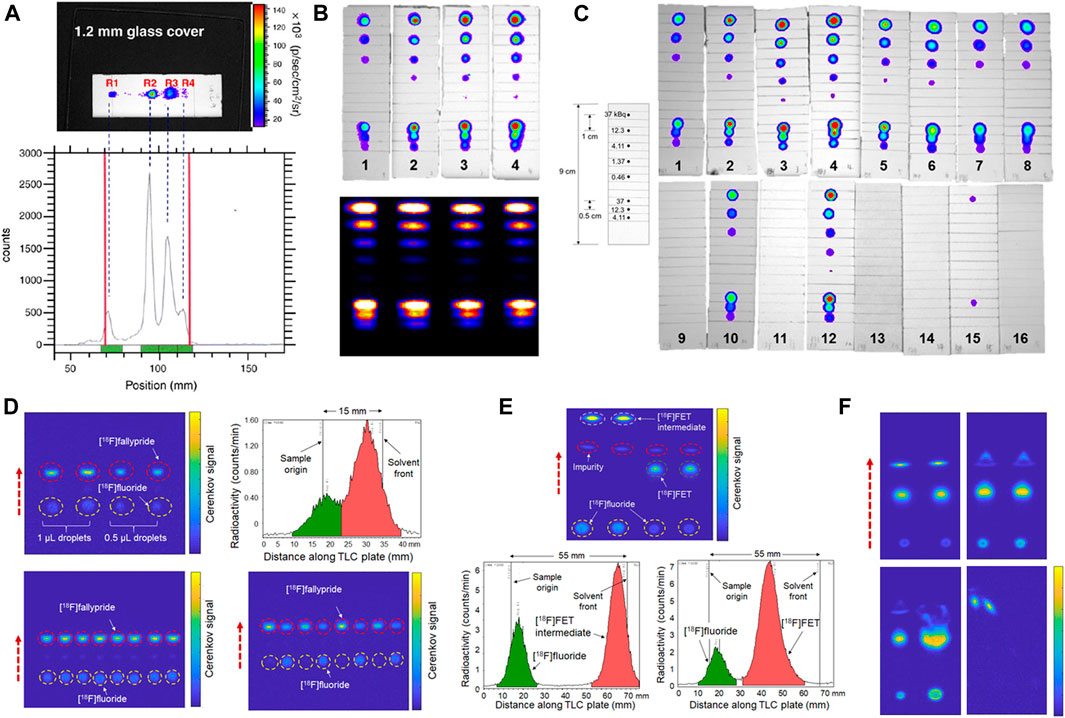
FIGURE 2. Use of Cerenkov imaging in the analysis of radiopharmaceuticals via radio-TLC. (A) Cerenkov image of TLC plate showing separation of multiple 131I-containing compounds (top), and corresponding profile from a radio-TLC scanner (bottom). Reproduced from [47], © 2011, with permission from Elsevier. (B) Cerenkov image of spots of iodine-131 on different types of TLC plates (top) and corresponding output from a 2D radio-TLC scanner (bottom). (C) Simultaneous imaging of 16 different types of TLC plates spotted multiple times each with iodine-131. The inset diagram (left) indicates the deposited amounts and spacing. (B,C) reproduced with permission from [48], © 2018, American Chemical Society. (D) Cerenkov image of one multi-lane TLC plate containing four samples of crude [18F]Fallypride spotted at different volumes and subject to only 15 mm separation (top left) and corresponding output of radio-TLC scanner of one representative lane cut from the multi-lane TLC plate (top right). Cerenkov images of plates containing 8 samples separated simultaneously (bottom two images). (E) Cerenkov image of one multi-lane TLC plate after 35 mm separation of the intermediate fluorination product and final product after deprotection (n = 2 each) in the synthesis of [18F]FET. Bottom graphs show corresponding output from radio-TLC scanner for one representative lane from each sample cut from the multi-lane TLC plate. (F) Illustration of qualitative value of Cerenkov imaging. Normal development process (top left); development after incomplete sample drying (top right); development with suitable and excessive sample volume (bottom left); and development when liquid contamination occurred on right side of plate during separation (bottom right). (D–F) adapted from [49], © 2020, with permission from Elsevier.
The Cerenkov signal can be boosted by placing a glass cover over the TLC plate in which additional Cerenkov light is generated [49], and even further light generation is possible by leveraging non-Cerenkov processes, through the use of phosphor-containing intensifying screens [50] or thin scintillators [49] over the TLC plate, or by relying on radioluminescence of fluorescent additives present in some commercial TLC plates [48]. The signal was also found to depend on TLC plate thickness, stationary phase material, and backing material [48].
Due to the large field of view of preclinical optical imaging systems, Ha et al. showed that sixteen 90-mm-long TLC plates (each prepared by spotting multiple amounts of radioisotope solutions), could be simultaneously imaged (Figure 2C). Extending this concept further, Wang et al. reported the possibility to spot multiple crude reaction samples side by side on a single TLC plate and perform simultaneous developing of all samples followed by simultaneous readout of all lanes, saving significant time and effort compared to processing samples on individual TLC plates [49]. Using the same Cerenkov imaging system as described above for observation of EWOD chips [35], which is much smaller and less expensive than a small-animal luminescence imaging system, a field of view of ∼50 × 50 mm could be imaged, enabling readout of 8 lanes spotted at 5 mm pitch (0.5 µl sample volume) [49]. This technique can be used to rapidly analyze the many samples generated in high-throughput droplet radiochemistry optimization studies [44]. In samples where very high separation resolution is not needed, the separation distance could be shortened significantly (e.g., from typical 55 mm length to 15 mm length for analysis of [18F]fallypride), leading to significant reduction in separation time (Figure 2D). The use of shorter plates also allowed multiple plates to be imaged at the same time (i.e., 2 plates with 8 lanes each). The high imaging resolution enabled detection of minor impurities in samples of crude [18F]FET and [18F]Fallypride that normally could only be detected via radio-HPLC (Figure 2E). In addition to 18F-labeled compounds, imaging of TLC plates containing crude [177Lu]Lu-PSMA-617 samples was also demonstrated. Quantitation of species via ROI analysis of Cerenkov images was more accurate and precise compared to the use of a conventional radio-TLC scanner [49].
The extra information provided via 2D readout instead of a conventional scanning detector was helpful for optimizing TLC conditions by allowing unambiguous assessment of separation quality (e.g., tailing), impact of sample volume, and separation resolution. It was also useful to detect characteristic artifacts indicative of poor radio-TLC separations (e.g., insufficient drying of sample spot, or contamination of TLC plate by a droplet before or during separation), enabling problematic assays to be repeated (Figure 2F).
Cerenkov luminescence imaging allows non-destructive, in situ, and nearly real-time monitoring of microfluidic radiosynthesis processes. For well-constrained planar geometries (channel networks in PDMS chips, sandwiched droplets in EWOD chips, or dried residues on chip surfaces), the signal can be calibrated for absolute quantitation of radioactivity via ROI analysis. Monitoring the distribution of radioactive species with CLI enabled detailed insights into droplet containment, mixing, evaporation, splashing, cross-contamination and surface fouling that were invisible to the naked eye, impossible to measure using other techniques, and sometimes unexpected. Cerenkov light is generated within the solvent of the reaction and/or the bulk material of the microfluidic chip, and doesn’t require the addition of scintillating materials. Though all the presented examples of microfluidic devices relied on detection of Cerenkov light produced in transparent media, the technique could also be used for other dielectric materials, limited by light absorption and scattering which attenuates Cerenkov signal and complicates quantitation. The ability to perform longitudinal observations of the same experiment accelerates progress and provides more conclusive information using fewer experiments than destructive measurement techniques.
As an analytical tool, CLI readout of radio-TLC plates enables high accuracy ROI analysis to quantitatively assess the proportion of different species in a sample. Though other readout methods (e.g., multiwire proportional counters) have been used in the past [45, 46], these technologies do not appear to play a significant role in the routine detection of radio-TLC signal, in part due to their limited availability as well as high instrument and maintenance costs. CLI provides a significant improvement in resolution compared to current scanning radio-TLC readers, and does not require collimation (which significantly reduces sensitivity). This high imaging resolution can be leveraged to achieve improved separation resolution or to reduce separation distance and time, and also enables use of multiple adjacent lanes to more efficiently process large numbers of samples. CLI has been shown to be compatible with a variety of positron- and beta-emitting isotopes for radio-TLC readout, and would also be applicable to monitoring the synthesis of radiopharmaceuticals containing any of these isotopes. Though CLI has lower sensitivity compared to scintillation-based approaches, this deficiency can be ameliorated by positioning a scintillator slab over the TLC plate provided the optical system has adequate sensitivity to distinguish individual scintillation pulses over electronic noise.
A current challenge facing adoption of CLI in both application areas is the availability of imaging equipment. Though CLI can be performed using commercially available preclinical luminescence imaging systems, such systems are expensive, bulky and not likely to be added to a radiochemistry laboratory. Alternatively, low-cost imaging systems can be built from inexpensive CCD or CMOS cameras and light-tight enclosures, but this requires significant specialized knowledge. Commercialization of a compact and low-cost CLI system tailored to radiochemistry applications, or development of an open-source design, could increase access to this measurement tool for the radiochemistry field.
We anticipate that CLI will be increasingly used in the development and characterization of new microfluidic technologies for radiosynthesis (and other process steps such as purification and formulation), as well as for optimization of radiochemistry processes implemented in these platforms. Microfluidic devices are beginning to find use in other aspects of nuclear chemistry including isotope production, nuclear energy, and radioactive waste remediation, and development of these devices may also benefit from CLI. Furthermore, radioisotopes provide a convenient way to accurately characterize liquid movement, residual losses, and adsorption (by radiolabeling a molecule of interest) in microfluidic devices in general; coupled with CLI for visualization and measurement, such high-sensitivity analytical techniques may find use in characterization of microfluidic devices and processes in a variety of other application areas. We also anticipate that CLI-based readout of radio-TLC plates will find increasing use in the radiochemistry field, especially in areas where visualization is beneficial such as the optimization of TLC separation conditions, and in high-throughput multi-lane separations. Such high-throughput analyses are beneficial in synthesis optimization and possibly in the analysis of radiometabolites. Additionally, combining CLI with other optical readouts (via the use of indicators and staining procedures) could enable more information to be obtained from each single radio-TLC plate, reducing the reliance on radio-HPLC.
RvD and AC wrote the manuscript.
This work was supported in part by the National Institute of Biomedical Imaging and Bioengineering (R21 EB024243) and in part by the National Cancer Institute P30 CA016042 Cancer Center Support Grant.
The authors declare that they hold a financial interest in Sofie, Inc., a private company which develops radiosynthesis technology, some of which is reviewed in this manuscript. The company was not involved in the writing of this article nor the decision to submit it for publication.
1. Cho JS, Douraghy A, Olma S, Liu K, Chen YC, Shen CK, et al. Čerenkov radiation imaging as a method for quantitative measurements of beta particles in a microfluidic chip. IEEE Nucl Sci Symposium Conf Rec (2008) 4510–5. doi:10.1109/NSSMIC.2008.4774293
2. Cho JS, Taschereau R, Olma S, Liu K, Chen YC, Shen CK, et al. Cerenkov radiation imaging as a method for quantitative measurements of beta particles in a microfluidic chip. Phys Med Biol (2009) 54:6757–71. doi:10.1088/0031-9155/54/22/001
3. Robertson R, Germanos MS, Li C, Mitchell GS, Cherry SR, Silva MD. Optical imaging of Cerenkov light generation from positron-emitting radiotracers. Phys Med Biol (2009) 54:N355–65. doi:10.1088/0031-9155/54/16/N01
4. Spinelli AE, D'Ambrosio D, Calderan L, Marengo M, Sbarbati A, Boschi F. Cerenkov radiation allows in vivo optical imaging of positron emitting radiotracers. Phys Med Biol (2010) 55:483. doi:10.1088/0031-9155/55/2/010
5. Mitchell GS, Gill RK, Boucher DL, Li C, Cherry SR. In vivo Cerenkov luminescence imaging: a new tool for molecular imaging. Philos Trans A Math Phys Eng Sci (2011) 369:4605–19. doi:10.1098/rsta.2011.0271
6. Ciarrocchi E, Belcari N. Cerenkov luminescence imaging: physics principles and potential applications in biomedical sciences. EJNMMI Phys (2017) 4:14. doi:10.1186/s40658-017-0181-8
7. Tanha K, Pashazadeh AM, Pogue BW. Review of biomedical Čerenkov luminescence imaging applications. Biomed Opt Express (2015) 6:3053–65. doi:10.1364/BOE.6.003053
8. Chin PT, Welling MM, Meskers SC, Valdes Olmos RA, Tanke H, van Leeuwen FW. Optical imaging as an expansion of nuclear medicine: Cerenkov-based luminescence vs fluorescence-based luminescence. Eur J Nucl Med Mol Imaging (2013) 40:1283–91. doi:10.1007/s00259-013-2408-9
9. Holland JP, Normand G, Ruggiero A, Lewis JS, Grimm J. Intraoperative imaging of positron emission tomographic radiotracers using Cerenkov luminescence emissions. Mol Imaging (2011) 10:177. doi:10.2310/7290.2010.00047
10. Grootendorst MR, Cariati M, Kothari A, Tuch DS, Purushotham A. Cerenkov luminescence imaging (CLI) for image-guided cancer surgery. Clin Transl Imaging (2016) 4:353–66. doi:10.1007/s40336-016-0183-x
11. Xu Y, Liu H, Cheng Z. Harnessing the power of radionuclides for optical imaging: Cerenkov luminescence imaging. J Nucl Med (2011) 52:2009–18. doi:10.2967/jnumed.111.092965
12. Das S, Thorek DL, Grimm J. Cerenkov imaging. In: MG Pomper, and PB Fisher, editors. Advances in cancer research emerging applications of molecular imaging to oncology, 124. London, United Kingdom: Academic Press (2014). p. 213–34. doi:10.1016/B978-0-12-411638-2.00006-9
13. Spinelli AE, Boschi F. Novel biomedical applications of Cerenkov radiation and radioluminescence imaging. Phys Med (2015) 31:120–9. doi:10.1016/j.ejmp.2014.12.003
14. Spinelli AE, Marengo M, Calandrino R, Sbarbati A, Boschi F. Optical imaging of radioisotopes: a novel multimodal approach to molecular imaging. Q J Nucl Med Mol Imaging (2012) 56:280–90.
15. Ma X, Wang J, Cheng Z. Cerenkov radiation: a multi-functional approach for biological sciences. Front Phys (2014) 2:4. doi:10.3389/fphy.2014.00004
16. Knapp KA, Nickels ML, Manning HC. The current role of microfluidics in radiofluorination chemistry. Mol Imaging Biol (2020) 22:463–75. doi:10.1007/s11307-019-01414-6
17. Keng PY, van Dam RM. Digital microfluidics: a new paradigm for radiochemistry. Mol Imaging (2015) 14:13–4. doi:10.2310/7290.2015.00030
18. Arima V, Pascali G, Lade O, Kretschmer HR, Bernsdorf I, Hammond V, et al. Radiochemistry on chip: towards dose-on-demand synthesis of PET radiopharmaceuticals. Lab Chip (2013) 13:2328–36. doi:10.1039/C3LC00055A
19. Rensch C, Jackson A, Lindner S, Salvamoser R, Samper V, Riese S, et al. Microfluidics: a groundbreaking technology for pet tracer production? Molecules (2013) 18:7930–56. doi:10.3390/molecules18077930
20. Lee CC, Sui G, Elizarov A, Shu CJ, Shin YS, Dooley AN, et al. Multistep synthesis of a radiolabeled imaging probe using integrated microfluidics. Science (2005) 310:1793–6. doi:10.1126/science.1118919
21. Elizarov AM, van Dam RM, Shin YS, Kolb HC, Padgett HC, Stout D, et al. Design and optimization of coin-shaped microreactor chips for PET radiopharmaceutical synthesis. J Nucl Med (2010) 51:282–7. doi:10.2967/jnumed.109.065946
22. Tseng W-Y, Cho JS, Ma X, Kunihiro A, Chatziioannou A, van Dam RM. Toward reliable synthesis of radiotracers for positron emission tomography in PDMS microfluidic chips: study and optimization of the [18F] fluoride drying process. In: Technical proceedings of the 2010 NSTI nanotechnology conference and trade show. Anaheim, CA: CRC Press (2010). 472–5. Available from: http://www.techconnectworld.com/World2010/a.html?i=599.
23. Tseng W-Y, Cho J, Ma X, Mahal K, Chatziioannou A, van Dam RM. PDMS evaporation chip to concentrate [18F]fluoride for synthesis of PET tracers in microfluidics. In: Proceedings of the fourteenth international conference on miniaturized systems for chemistry and life sciences. Groningen; 2010 Oct 3–7; The Netherlands, (2010). 1010–2.
24. Tseng W-Y, Cho JS, Chatziioannou A, van Dam RM. Interdigitated evaporation chip for efficient solvent exchange in microchannels. In: Proceedings of the 16th international conference on miniaturized systems for chemistry and life sciences; 2012 Oct 28–Nov 1, Okinawa, Japan: Royal Society of Chemistry (2008–2010). (2012).
25. Salvador B, Luque A, Fernandez-Maza L, Corral A, Orta D, Fernández I, et al. Disposable PDMS chip with integrated [18F]fluoride pre-concentration cartridge for radiopharmaceuticals. J Microelectromech Syst (2017) 26:1442–8. doi:10.1109/JMEMS.2017.2764121
26. Salvador B, Escalante D, Fernandez-Maza L, Corral A, Camacho-Leon S, Luque A. Monitoring of microfluidics systems for PET radiopharmaceutical synthesis using integrated silicon photomultipliers. IEEE Sens J (2019) 1:7702–7. doi:10.1109/JSEN.2019.2917362
27. Zhang X, Liu F, Knapp KA, Nickels ML, Manning HC, Bellan LM. A simple microfluidic platform for rapid and efficient production of the radiotracer [18F]fallypride. Lab Chip (2018) 18:1369–77. doi:10.1039/C8LC00167G
28. Zhang X, Liu F, Payne AC, Nickels ML, Bellan LM, Manning HC. High-yielding radiosynthesis of [68Ga]Ga-PSMA-11 using a low-cost microfluidic device. Mol Imaging Biol (2020) 22:1370–79. doi:10.1007/s11307-020-01515-7
29. Wheeler TD, Zeng D, Desai AV, Önal B, Reichert DE, Kenis PJ. Microfluidic labeling of biomolecules with radiometers for use in nuclear medicine. Lab Chip (2010) 10:3387–96. doi:10.1039/c0lc00162g
30. Zeng D, Desai AV, Ranganathan D, Wheeler TD, Kenis PJ, Reichert DE. Microfluidic radiolabeling of biomolecules with PET radiometers. Nucl Med Biol (2013) 40:42–51. doi:10.1016/j.nucmedbio.2012.08.012
31. Wright BD, Whittenberg J, Desai A, DiFelice C, Kenis PJ, Lapi SE, et al. Microfluidic preparation of a 89Zr-labeled trastuzumab single-patient dose. J Nucl Med (2016) 57:747–52. doi:10.2967/jnumed.115.166140
32. Chen YC, Liu K, Shen CK, van Dam RM. On-demand generation and mixing of liquid-in-gas slugs with digitally-programmable composition and size. J Micromech Microeng (2015) 25:084006. doi:10.1088/0960-1317/25/8/084006
33. Liu K, Lepin EJ, Wang MW, Guo F, Lin WY, Chen YC, et al. Microfluidic-based 18F-labeling of biomolecules for immuno-positron emission tomography. Mol Imaging (2011) 10:168–7. doi:10.2310/7290.2010.00043
34. Keng PY, Chen S, Ding H, Sadeghi S, Shah GJ, Dooraghi A, et al. Micro-chemical synthesis of molecular probes on an electronic microfluidic device. Proc Natl Acad Sci USA (2012) 109:690–5. doi:10.1073/pnas.1117566109
35. Dooraghi AA, Keng PY, Chen S, Javed MR, Kim CJ, Chatziioannou AF, et al. Optimization of microfluidic PET tracer synthesis with Cerenkov imaging. Analyst (2013) 138:5654–64. doi:10.1039/C3AN01113E
36. Javed MR, Chen S, Kim HK, Wei L, Czernin J, Kim CJ, et al. Efficient radiosynthesis of 3'-deoxy-3'-18F-fluorothymidine using electrowetting-on-dielectric digital microfluidic chip. J Nucl Med (2014) 55:321–8. doi:10.2967/jnumed.113.121053
37. Javed MR, Chen S, Lei J, Collins J, Sergeev M, Kim HK, et al. High yield and high specific activity synthesis of [18F]fallypride in a batch microfluidic reactor for micro-PET imaging. Chem Commun (Camb) (2014) 50:1192–4. doi:10.1039/C3CC47616B
38. Kim H-K, Rashed Javed M, Chen S, Zettlitz K A, Collins J, Wu A M, et al. On-demand radiosynthesis of N -succinimidyl-4-[ 18 F]fluorobenzoate ([18 F]SFB) on an electrowetting-on-dielectric microfluidic chip for 18 F-labeling of protein. RSC Adv (2019) 9:32175–83. doi:10.1039/C9RA06158D
39. Chen S, Javed MR, Kim HK, Lei J, Lazari M, Shah GJ, et al. Radiolabelling diverse positron emission tomography (PET) tracers using a single digital microfluidic reactor chip. Lab Chip (2014) 14:902–10. doi:10.1039/C3LC51195B
40. Chen S, Dooraghi A, Lazari M, van Dam RM, Chatziioannou AF, Kim C-J. On-chip product purification for complete microfluidic radiotracer synthesis. In: Proceedings of the 27th IEEE international conference on micro electro mechanical systems (MEMS); 26–30 January 2014; San Francisco, CA (2014) 284–7. doi:10.1109/MEMSYS.2014.6765631
41. Wang J, Chao PH, Hanet S, van Dam RM. Performing multi-step chemical reactions in microliter-sized droplets by leveraging a simple passive transport mechanism. Lab Chip (2017) 17:4342–55. doi:10.1039/C7LC01009E
42. Wang J, Chao PH, Slavik R, Dam RM. Multi-GBq production of the radiotracer [18F]fallypride in a droplet microreactor. RSC Adv (2020) 10:7828–38. doi:10.1039/D0RA01212B
43. Wang J, Chao PH, van Dam RM. Ultra-compact, automated microdroplet radiosynthesizer. Lab Chip (2019) 19:2415–24. doi:10.1039/C9LC00438F
44. Rios A, Wang J, Chao PH, Dam RM. A novel multi-reaction microdroplet platform for rapid radiochemistry optimization. RSC Adv (2019) 9:20370–4. doi:10.1039/C9RA03639C
45. Dietzel G, Kubisiak H, Stelzer H. A note on: development of 2-dimensional detectors for radio-thin-layer chromatography. In: FAA Dallas, H Read, RJ Ruane, and ID Wilson, editors. Recent advances in thin-layer chromatography. Boston, MA: Springer US (1988). 117–23. doi:10.1007/978-1-4899-2221-2_12
46. Decristoforo C, Zaknun J, Kohler B, Oberladstaetter M, Riccabona G. The use of electronic autoradiography in radiopharmacy. Nucl Med Biol (1997) 24:361–5. doi:10.1016/S0969-8051(97)00055-3
47. Park JC, Il An G, Park SI, Oh J, Kim HJ, Su Ha Y, et al. Luminescence imaging using radionuclides: a potential application in molecular imaging. Nucl Med Biol (2011) 38:321–9. doi:10.1016/j.nucmedbio.2010.09.003
48. Ha YS, Lee W, Jung JM, Soni N, Pandya DN, An GI, et al. Visualization and quantification of radiochemical purity by Cerenkov luminescence imaging. Anal Chem (2018) 90:8927–35. doi:10.1021/acs.analchem.8b01098
49. Wang J, Rios A, Lisova K, Slavik R, Chatziioannou AF, van Dam RM. High-throughput radio-TLC analysis. Nucl Med Biol (2020) 82–83:41–8. doi:10.1016/j.nucmedbio.2019.12.003
Keywords: radiochemistry, radiosynthesis module, radiosynthesis optimization, Cerenkov, microfluidic, radio-TLC, positron emission tomography, theranostics
Citation: van Dam RM and Chatziioannou AF (2021) Cerenkov Luminescence Imaging in the Development and Production of Radiopharmaceuticals. Front. Phys. 9:632056. doi: 10.3389/fphy.2021.632056
Received: 22 November 2020; Accepted: 22 January 2021;
Published: 03 March 2021.
Edited by:
Antonello Enrico Spinelli, San Raffaele Scientific Institute, ItalyReviewed by:
Jason Holland, University of Zurich, SwitzerlandCopyright © 2021 van Dam and Chatziioannou. This is an open-access article distributed under the terms of the Creative Commons Attribution License (CC BY). The use, distribution or reproduction in other forums is permitted, provided the original author(s) and the copyright owner(s) are credited and that the original publication in this journal is cited, in accordance with accepted academic practice. No use, distribution or reproduction is permitted which does not comply with these terms.
*Correspondence: R. Michael van Dam, mvandam@mednet.ucla.edu
†These authors have contributed equally to this work
Disclaimer: All claims expressed in this article are solely those of the authors and do not necessarily represent those of their affiliated organizations, or those of the publisher, the editors and the reviewers. Any product that may be evaluated in this article or claim that may be made by its manufacturer is not guaranteed or endorsed by the publisher.
Research integrity at Frontiers
Learn more about the work of our research integrity team to safeguard the quality of each article we publish.