 Yanchun Xie1
 Yao Wu
- 1Department of Orthopedics, General Hospital of Northern Theater Command, Shenyang, China
- 2Daniel L. Goodwin College of Business, Benedictine University, Chicago, IL, United States
- 3Faculty of Robot Science and Engineering, Northeastern University, Shenyang, China
This paper introduces the flexible control and trajectory planning medical two-arm surgical robots, and employs effective collision detection methods to ensure the safety and precision during tasks. Firstly, the DH method is employed to establish relative rotation matrices between coordinate systems, determining the relative relationships of each joint link. A neural network based on a multilayer perceptron is proposed to solve FKP problem in real time. Secondly, a universal interpolator based on Non-Uniform Rational B-Splines (NURBS) is developed, capable of handling any geometric shape to ensure smooth and flexible motion trajectories. Finally, we developed a generalized momentum observer to detect external collisions, eliminating the need for external sensors and thereby reducing mechanical complexity and cost. The experiments verify the effectiveness of the kinematics solution and trajectory planning, demonstrating that the improved momentum torque observer can significantly reduce system overshoot, enabling the two-arm surgical robot to perform precise and safe surgical tasks under algorithmic guidance.
1 Introduction
With the continuous development of medical technology and the progress of robot technology, more and more robots are applied in the medical industry (Zhong et al., 2019). The flexible control and trajectory planning of medical dual-arm collaborative robots are crucial technologies enabling these robots to perform various complex tasks in the medical field, such as surgical assistance (Wu et al., 2019) and rehabilitation training (Culmer et al., 2009). Flexible control (Chalhoub and Ulsoy, 1987) refers to the ability of the robot control system to adapt to external environments and task requirements. For example, in the medical surgery, the responsive implementation, real-time control systems are crucial. These systems are adept at detecting and adjusting to minute fluctuations within the patient internal environment, thereby ensuring both the precision and safety of surgical procedures. Additionally, these adaptable control systems make robots more skilled and flexible when they do difficult jobs. This is most noticeable when robots have to do tasks when they are working closely with people. Flexible control is often closely related to trajectory planning in medical dual-arm robots (Kojima and Kibe, 2001; Kojima, 2002).
Trajectory planning refers to determining the robot motion trajectory in the workspace to enable it to accomplish specified tasks (Asada et al., 1990). In medical dual-arm robots, trajectory planning must consider factors such as anatomical structures of the surgical area, surgical objectives, and safety to ensure that the robot motion can reach the expected positions accurately and safely.
In the standard operational procedures for industrial robots, ensuring both the robot functionality and the staff safety are paramount. To achieve this, a physical barrier is commonly implemented. This barrier serves to segregate the robot from the surrounding area or to delineate the operational zones of both the staff and the robot. This strategic separation effectively prevents any direct physical contact between the staff and the robotic equipment. In the medical sector, however, there is a distinct preference for robots that can collaborate closely with human operators. This necessitates the capability of robots to execute a multitude of tasks securely within the intricate and demanding conditions of surgical settings. The robots must be designed to operate harmoniously with medical professionals, ensuring that they can contribute effectively to the high-precision requirements of healthcare without compromising safety. Collision protection of medical dual-arm collaborative robots is critical to ensuring robot safe operation when working with humans. This protection typically employs various technologies and methods:
1. Sensor technology (Zeng and Bone, 2013; Popov et al., 2017; Li et al., 2020): Sensors installed at various vital parts of the robot, such as arms and around the body, detect proximity or collisions. These sensors can be proximity, photoelectric, or pressure sensors, among others.
2. Vision systems (Mohammed et al., 2017): Vision systems using cameras or laser scanners are utilized to detect the surrounding environment and human positions and timely identify potential collision hazards.
3. Collision detection algorithms (Cao et al., 2019; Han et al., 2019): Software algorithms analyze data provided by sensors and vision systems to determine the presence of collision risks and take corresponding measures to avoid collisions.
Adding sensors to the above collision detection method will increase the cost of the robot system, while sensorless collision detection will use acceleration information, which will lead to the introduction of interference and error.
In the robot arm kinematics, the research approaches (Venanzi and Parenti-Castelli, 2005; Pandey and Zhang, 2012) for kinematics modeling and parameter identification have reached a high level of maturity. Rectifying the kinematics parameters based on the general error model can directly enhance the accuracy of the robot arm end position. However, the following drawbacks may emerge during the process: a significant amount of calculation, a long period for identification parameter iteration, which severely affects the motion velocity. During the medical robot operating process, it is challenging to employ sensors to detect and provide real-time feedback on the end pose. Nevertheless, the artificial neural network (ANN) boasts strong self-learning and adaptive capabilities (Aoyagi et al., 2012; Angelidis and Vosniakos, 2014). In recent years, ANN has been extensively utilized in domains such as system optimization and intelligent control, among which the BP (Back Propagation) neural network is a multi-layer feedforward network trained in accordance with the reverse propagation algorithm. Utilizing the algorithm based on the neural network to estimate the pose at the end of the manipulator can circumvent certain issues in the process of parameter calibration.
This study delves into neural network technology, analyzing the inverse kinematics problem (IKP) and forward kinematics problem (FKP). The current FKP solving strategy relies on iterative methods, which incur high computational costs and long processing times and cannot achieve optimal real time operations. This paper proposes a neural network utilizing an improved form of multilayer perceptron for backpropagation learning to enhance the accuracy of solving the mechanical arm forward kinematics problem to the desired level and achieve real-time solutions.
Furthermore, the study investigates the establishment of NURBS curve-related techniques. It integrates NURBS curves into trajectory interpolation of medical dual-arm collaborative robots capable of handling any geometric shape. Additionally, this paper introduces compensation and variable damping design into the collision detection method based on the second-order momentum torque observer to improve robot collision detection real-time accuracy.
2 Related work
In the rapidly evolving medical industry landscape today, robotic automation has gradually entered the realm of medical systems. Traditional assembly processes of medical assistive devices are increasingly unable to meet the demands of modern medical production. Simultaneously, there is a growing demand for robots with high safety, stability, and flexibility to assist in collaborative operations during medical device-assisted drug dispensing. Robots can replace many tasks in medical drug dispensing. Manual solutions such as medication dispensing, assisting in guiding needles, and tumor resection using medical assistive devices must be updated. Medical dual-arm collaborative robots can perform complex drug dispensing processes, as depicted in Figure 1. The application of the medical dual-arm collaborative robot software platform in the medical assistive industry offers unparalleled advantages. These robots facilitate the drug dispensing process and enable collaboration between workers and robots. Integrating manual drug dispensing tasks with automated production addresses the labor-intensive operations in the medical industry. Moreover, the arms of these robots must possess the functionality for coordinated dual-arm operations to ensure synchronous and precise coordination and collision prevention.
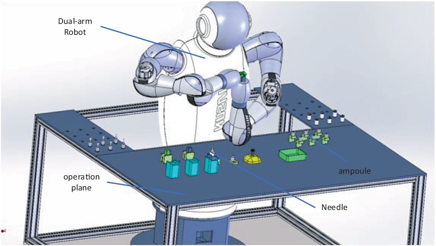
Figure 1. Medical dual-arm collaborative robot.
2.1 Classification of robot interactive control
The classification of robot interaction control is illustrated in Figure 2. Common control methods (Niku, 2020) mainly include force/position hybrid control and impedance/admittance control. In several studies (Hogan, 1985; Anderson and Spong, 1988) on impedance control, a prescribed fixed passive impedance model is defined, and efforts are then focused on addressing challenges such as dealing with uncertainties. Research within this framework typically adopts either learning-based (Sharifi et al., 2021) or adaptive impedance control (Yu et al., 2019). However, assuming that a fixed impedance model is no longer sufficient to describe specific applications, such as explosive movements or Human-Robot Interaction (HRI). Therefore, adopting variable impedance control (Ikeura and Inooka, 1995) must be considered for robot interaction control. However, adjusting impedance parameters to provide optimal impedance characteristics is more effective in enhancing interaction performance, which is necessary for essential applications such as HRI. Physically informed HRI has been proposed in adaptive impedance kinematics learning. In this study (Dong and Ren, 2017), robots adapt their movements by learning tasks to predict the intentions of their partners. Optimal impedance adaptation in constrained motion HRI has been investigated (Sun et al., 2019). Continuous critic learning is employed for interaction control, followed by obtaining the desired impedance as the optimal implementation to meet the control objectives. However, adaptive control is not appropriate for the control system with a high real-time demand, and it is deficient in the capacity to handle nonlinear issues. Fuzzy control. The fuzzy processing of the control parameters might cause the reduction of precision and the deterioration of the dynamic quality of the force interaction control.
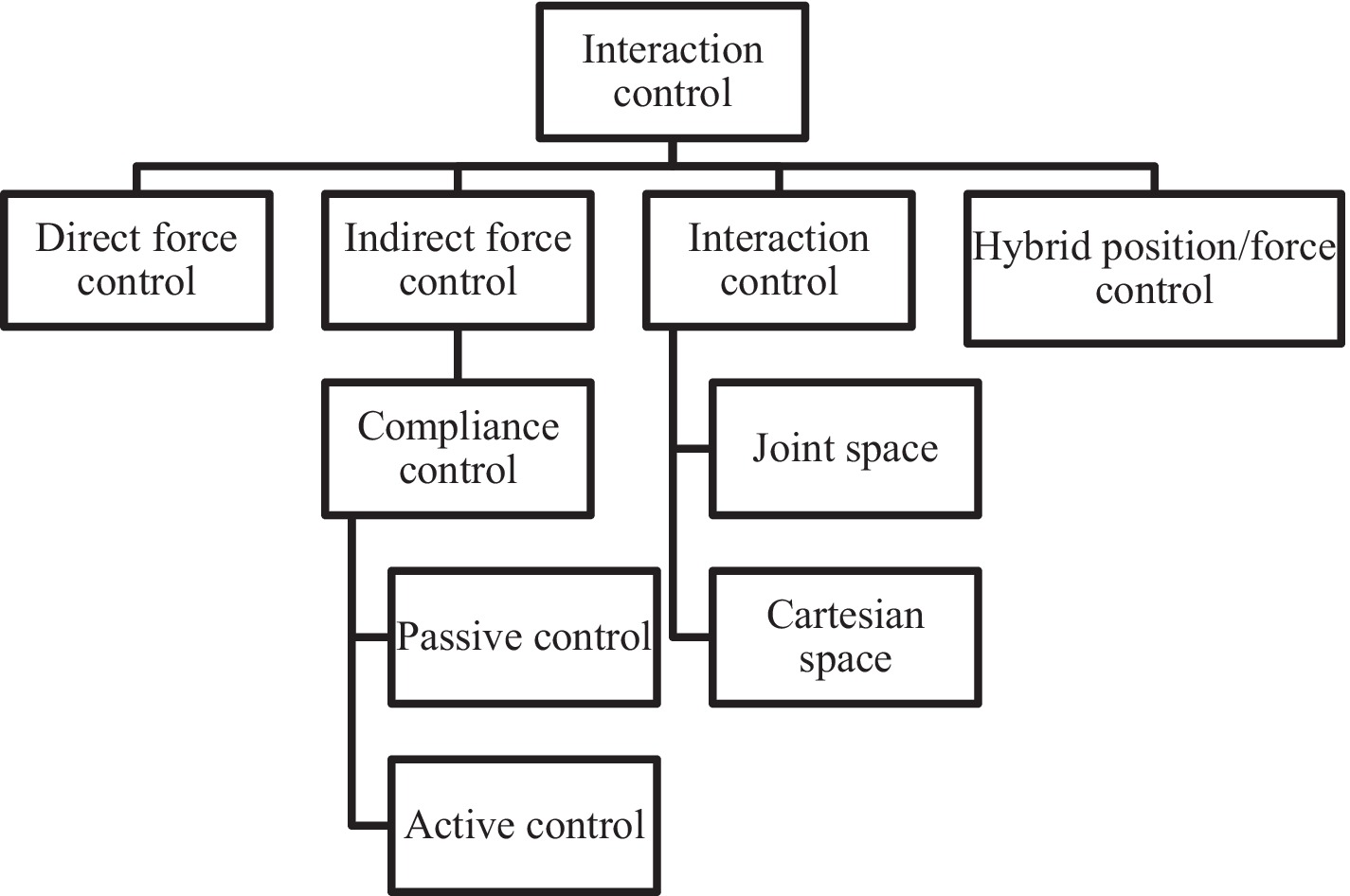
Figure 2. System composition of cleaning robot.
Li et al. (Li et al., 2016) explores the cooperative kinematic control of multiple manipulators through distributed recurrent neural networks and offers a feasible approach to extend the existing outcomes on individual manipulator control by using recurrent neural networks to the circumstance of the coordination of multiple manipulators. Jin et al. (Jin et al., 2022) analyses a collaborative control problem of redundant manipulators with time delays and proposes a time-delayed and distributed neural dynamics scheme. Yang et al. (Yang et al., 2023) proposes an Extended Kalman Filter-incorporated Residual Neural Network-based Calibration (ERC) model for kinematic calibration.
2.2 Arm mechanical structure
As shown in Figure 3, the shoulder and elbow joints are designed with dual-degree mechanisms, differing only in motor arrangement. The motor achieves arm abduction through bevel gear transmission, while the offset motor achieves arm flexion and extension through spur gear transmission. The structural principles of the elbow joint are the same as those of the shoulder joint.
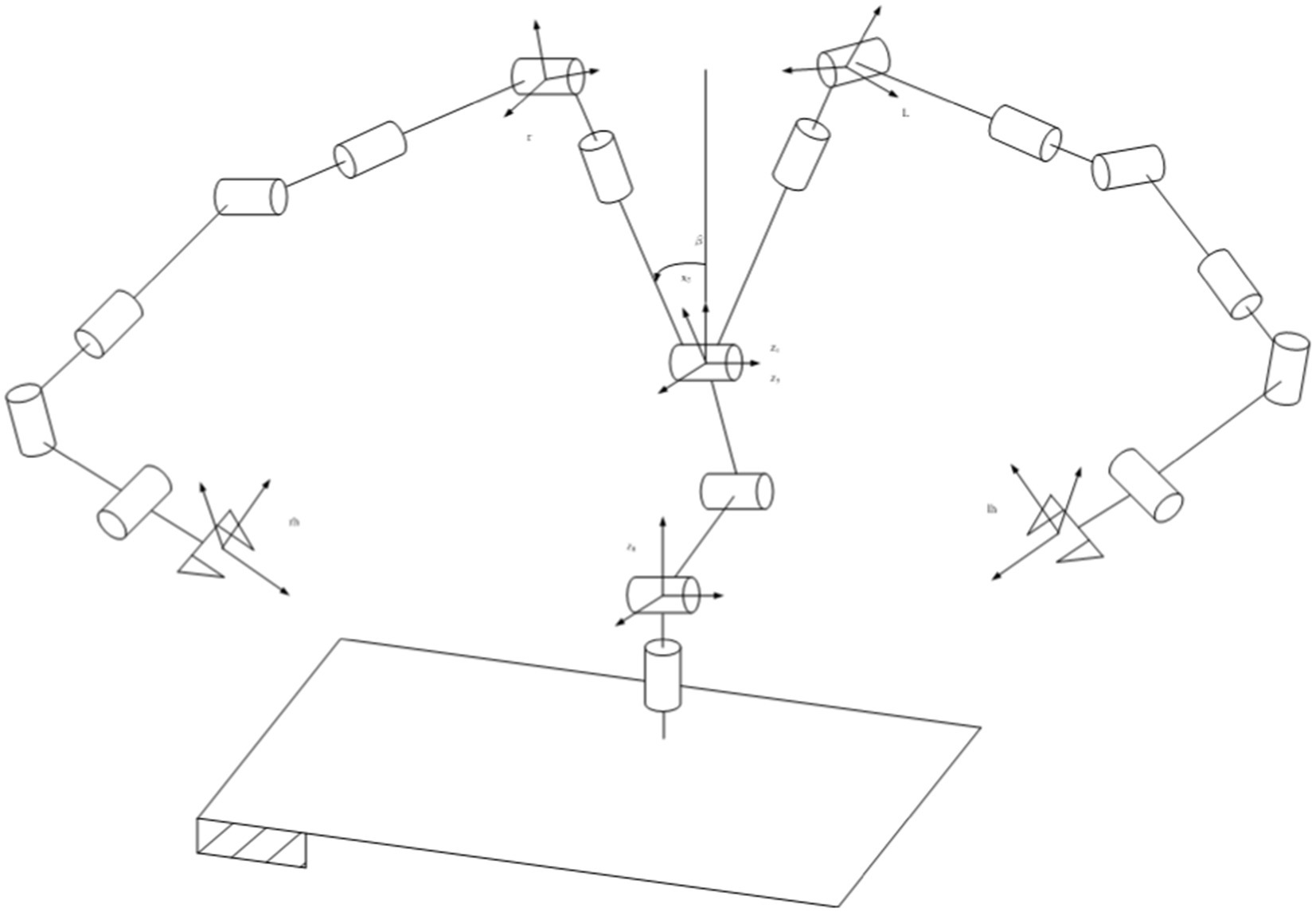
Figure 3. Coorinate system distribution.
Peripheral components such as end effectors and dexterous hands are installed at the end, and backlash compensation is applied to the spur gear transmission system through an eccentric flange. The arm integrates driver boards for the elbow and wrist motors, facilitating later debugging and maintenance. Touch sensor modules can also be installed inside the arm to perceive human contact and respond with corresponding actions such as speech or facial expressions, enhancing interaction with humans.
3 Motion control and spline trajectory planning
3.1 Motion control of medical two-arm robot
3.1.1 Kinematics forward solution
The humanoid two-arm robot has 14 degrees of freedom and can be analyzed for one hand and the other hand. The optional position of the base coordinate system is not unique. Establishing a coordinate system in the above way can facilitate the analysis of the geometric relationship between each joint value and the robot pose. Compared with the traditional D-H method, the homogeneous transformation matrix between the adjacent joints of the robot can be intuitively obtained during the forward solution process. At the same time, the calculation amount of inverse kinematics analysis can be reduced to a certain extent (Liu et al., 2021). This method is suitable for fast modeling in engineering, can simplify the derivation of kinematic relations, facilitate the acquisition of kinematic equations, and make the results more intuitive. Since the arm position is decoupled from the attitude, the first four joints and the wrist are calculated separately to facilitate the inverse solution. The robot is divided into four freedom degrees ( ) at the lower part of the wrist and three degrees freedom ( ) at the end of the wrist joint. The forward kinematics is analyzed from the four joints at the base and three joints at the end. For the left hand, the transformation matrix from 1 to 7 can be obtained according to the spatial geometric relationship of each joint, as shown in Equation 1.
The conclusion is as follows:
3.1.2 Neural network solution
Installing additional sensors or transducers at the end of medical dual-arm collaborative robots to gather more information about the system state (robotic arm) may facilitate the rapid and convenient resolution of Forward Kinematics Problems (FKP). However, the additional cost of sensors renders it less than ideal. In iterative methods, kinematic problems are formalized, allowing them to be solved using any available numerical techniques. However, these numerical techniques are computationally intensive and cannot guarantee a solution.
The analytical approach of solving FKP based on neural networks is not limited to the specific structure of medical dual-arm collaborative robots; it can be extended to other types of six-axis medical dual-arm collaborative robots or generalized medical dual-arm collaborative robots. Neuron processing units sum modified signals and apply the result to a linear or nonlinear activation function. Subsequently, the generated signal or value is transmitted to output units. Inputs, weights, architecture, and thresholds are parameters neural network unit control.
Once the network designers determine the neural network architecture, weight values can be set through a training or learning process. In network training, the neural network free parameters (weights) adapt through a continuous stimulation process of the environment, embedding the network. Environmental stimuli are input–output data values obtained from different states of the environment. Free parameters are systematically updated during the training process to converge to optimal values. The learning rate controls the magnitude of free parameter updates. When to stop training depends on predefined conditions, such as reaching the maximum expected training time and the lowest error rate. The accuracy of neural network parameters and the amount of learning data are closely related to the learning process resembling that of the human brain. Inputs are the joint angles of the medical dual-arm collaborative robot, and the output of the neural network module is the position and posture of the robot end effector. First, nonlinear equations are established, as shown in Equation 6.
According to the aforementioned nonlinear equations, a three-layer BP neural network method is adopted to perform forward kinematics solution for medical dual-arm collaborative robot. As illustrated in Figure 4, the neural network topology consists of three layers, with the input layer comprising 3 neurons and the output layer containing 4 neurons. The nonlinear mapping of the robot forward kinematics can be converted into a linear mapping via Equation 7, where N samples are designated as , with . Here, represents the network input vector, serving as the j-th positional sample, and represents the network output vector corresponding to the j-th motor angle.
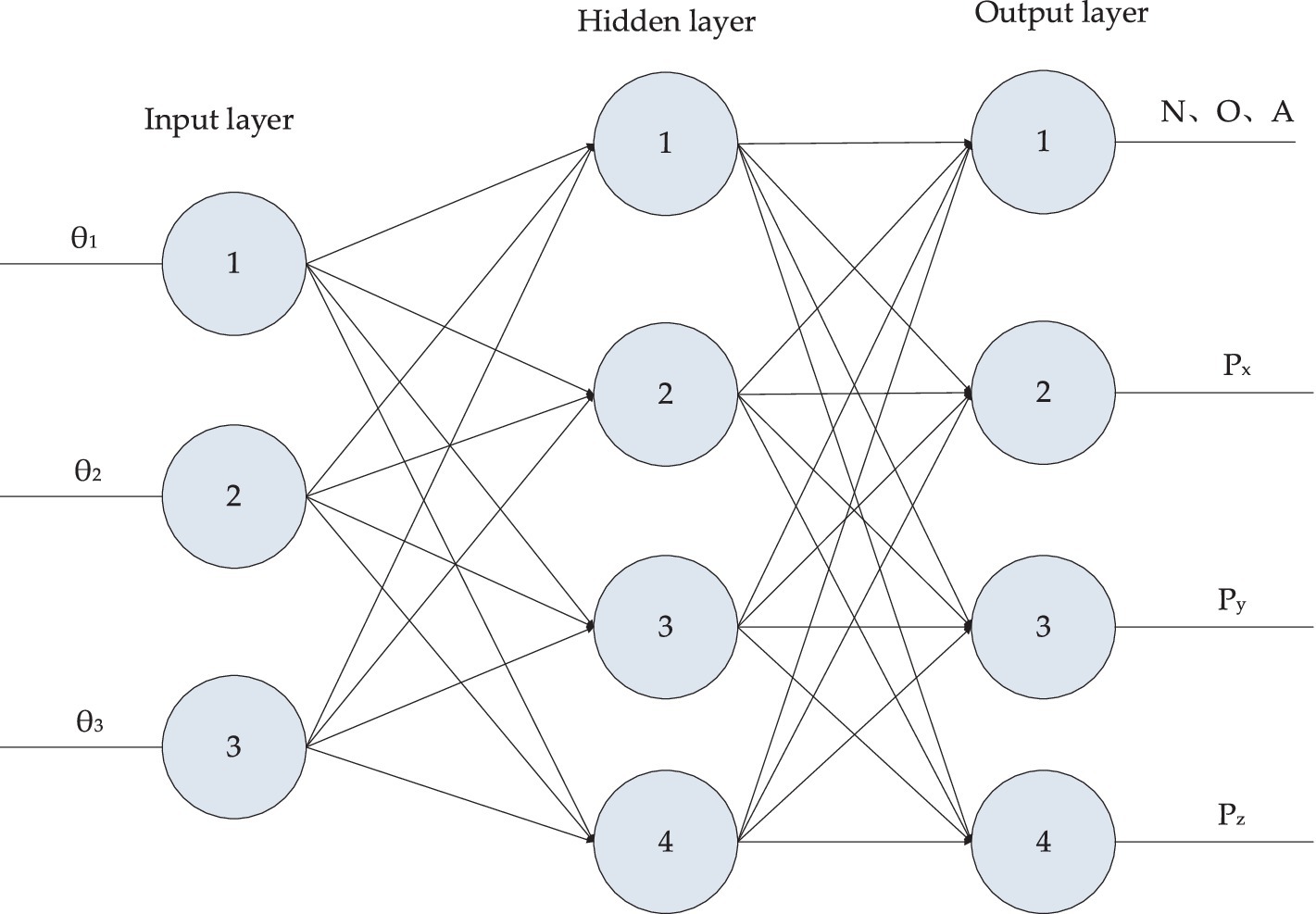
Figure 4. Three-layer feedforward neural network.
Where: and are the weights and thresholds of the node i of the hidden layer and the input layer; and are the weights and thresholds between the output layer and the hidden layer.
From the experience gained through network training, it is understood that the number of training samples should be approximately 5 to 10 times the number of network weights. Once the sample set is determined, the initial step involves normalizing the input and output data of the neural network, ensuring that all data points are scaled to the range [−1, 1]. In the architecture of the BP network, the middle-hidden layer plays a pivotal role in the network performance, as it receives calculated results from the input layer and passes them to the output layer. Therefore, the activation function used in the hidden layer must be continuous and smooth to facilitate effective learning. Given its favorable properties and compliance with these criteria, the sigmoid function is chosen as the activation function for the hidden layer of the neural network. This choice is made to enhance the network ability to model complex relationships within the data.
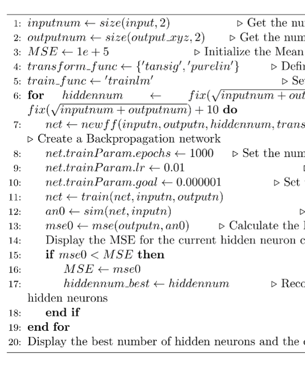
We take the position, velocity and acceleration of each joint as input to form an 18-dimensional input vector, and take the spatial coordinates of the end joints as output. The optimal number of hidden layers of the neural network can be obtained by empirical formula, which can be specifically seen in Algorithm 1. Using MSE as a metric, we can calculate that the best hidden layer node is 11. The whole network structure is shown in Figure 5. The training results are shown in Figure 6.
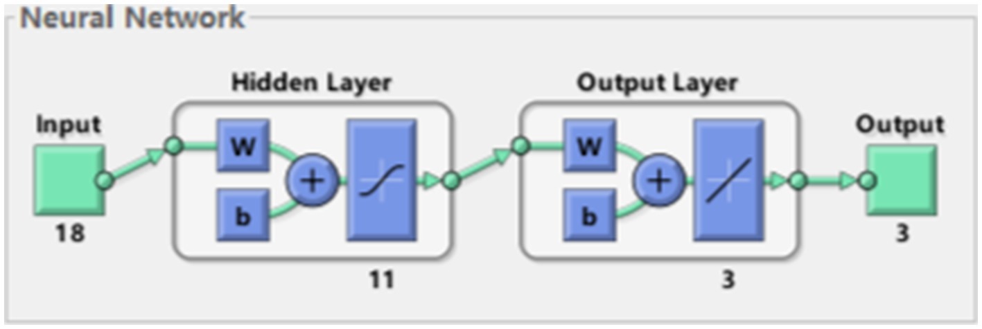
Figure 5. Network structure.
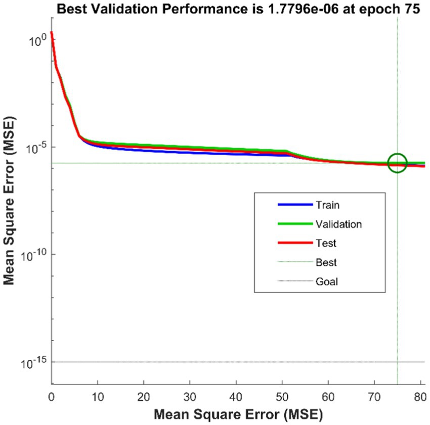
Figure 6. BP train result.
ALGORITHM 1. Optimal hidden neuron count for a backpropagation network
In the motion control process of the medical dual-arm collaborative robot, a large number of positions and joint angles are saved as samples. After training with these samples as inputs, the kinematic forward description from robot joint angles to robot end effector positions can be obtained. This allows the establishment of the nonlinear equations and weights to derive the forward kinematics of the medical dual-arm collaborative robot.
3.2 Trajectory planning with NURBS
NURBS (Non-Uniform Rational B-Splines) spline curves are a commonly used mathematical representation method in computer graphics and computer-aided design (CAD). A series of control points, weights, and knot vectors define them. NURBS curves are widely used in computer graphics and CAD because they can accurately represent various curve shapes and have good mathematical properties such as local control, smoothness, and adjustability. This makes them essential tools in design and modeling work.
The steps for NURBS spline curve planning involve specific algorithms to calculate the feed rate and sample points for each sampling interval, as this motion planning is implemented in real time. The NURBS spline curve fitting process is illustrated in Figure 7.
(1) Calculation process of node parameter (cumulative chord length method)
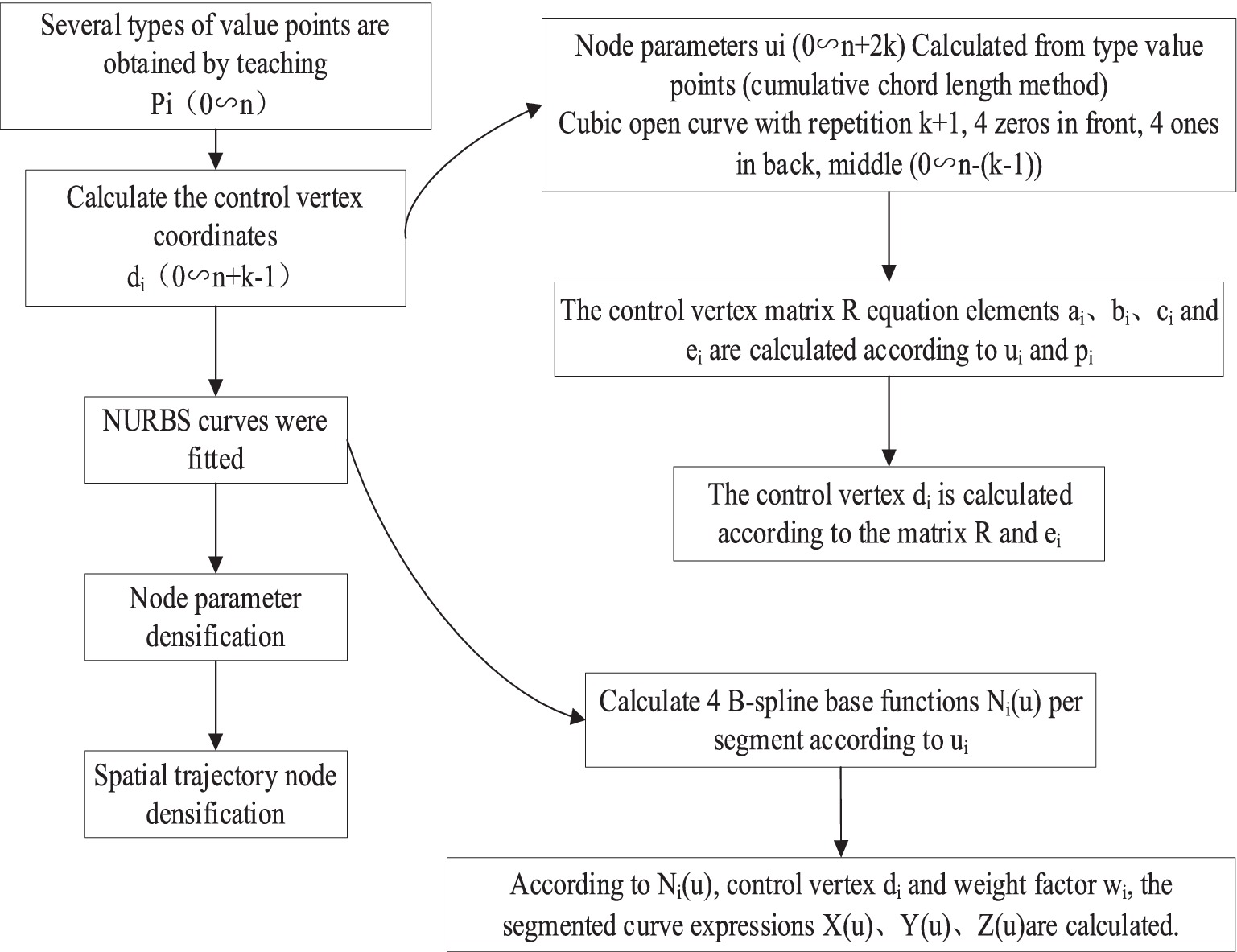
Figure 7. NURBS spline curve fitting proces.
According to joint displacement time node sequence ; By definition, the corresponding node vector is ; The specific expression is shown in Equation 9.
Formula calculated by cumulative chord length method:
(2) The calculation process of matrix R elements is shown in Equations 8 and 11.
(3) Control the calculation process of vertex
The control vertex is calculated according to the following Equation 12.
From the NURBS first and last points (control points), the Equation 13 can be obtained.
(4) B spline basis function has been calculated; The four basis functions of each segment B spline should be calculated according to the following formula, and the four basis functions corresponding to should be calculated periodically for each segment, as shown in Equation 14.
(5) Subsection curve expression calculation process
Calculate the expression of each B spline curve according to the following Equation 15, which needs to be calculated periodically for each segment:
At this stage, the B spline curve is fitted. Next, the curve data points need to be densified to enable the robot to walk to each densification point periodically. This densification is generally achieved through Taylor expansion.
3.3 Collision detection basics
Considering the influence of the external collision torque and the friction torque, the robot dynamic equation can be written as Equation 16. represent the robot joint angle, angular velocity and angular acceleration, respectively. Robot inertia matrix is D. Coriolis matrix is C. Gravitational term is G. The external impact is equivalent to the external torque of each joint is . Robot joint friction torque is . Robot motor drive torque is .
As can be seen from the Equation 16, solving requires the acceleration, but it will bring noise. So we design an observer based on generalized momentum. The robot generalized momentum is defined as Equation 17.
We define an observation vector r. The torque gain matrix is K1 and K2. is the estimate of P. The second-order observer is shown in Equation 18.
We optimize this second-order observer by introducing links such as Equation 19.
Finally, the resulting observer is shown in Equation 20.
4 Simulation analysis and experimental verification
4.1 Network verification
In the exploration of applying neural networks to solve the FKP, we initially collected the requisite datasets in accordance with established approaches. Subsequently, we employed BP neural network technology to train the model systematically, with the parameters of the joint motor serving as the input of the network and the coordinate position of the robot arm end as the output target.
Once the model training was accomplished, we randomly chose some data samples that were not encompassed in the training to test the prediction capability of the neural network. Based on the outcomes presented in Figure 8, we discovered that the neural network could precisely predict the coordinate position of the robot arm end. This finding thoroughly substantiates that the approach of leveraging the BP neural network to predict the position of the robot arm end is not only feasible but also highly accurate.
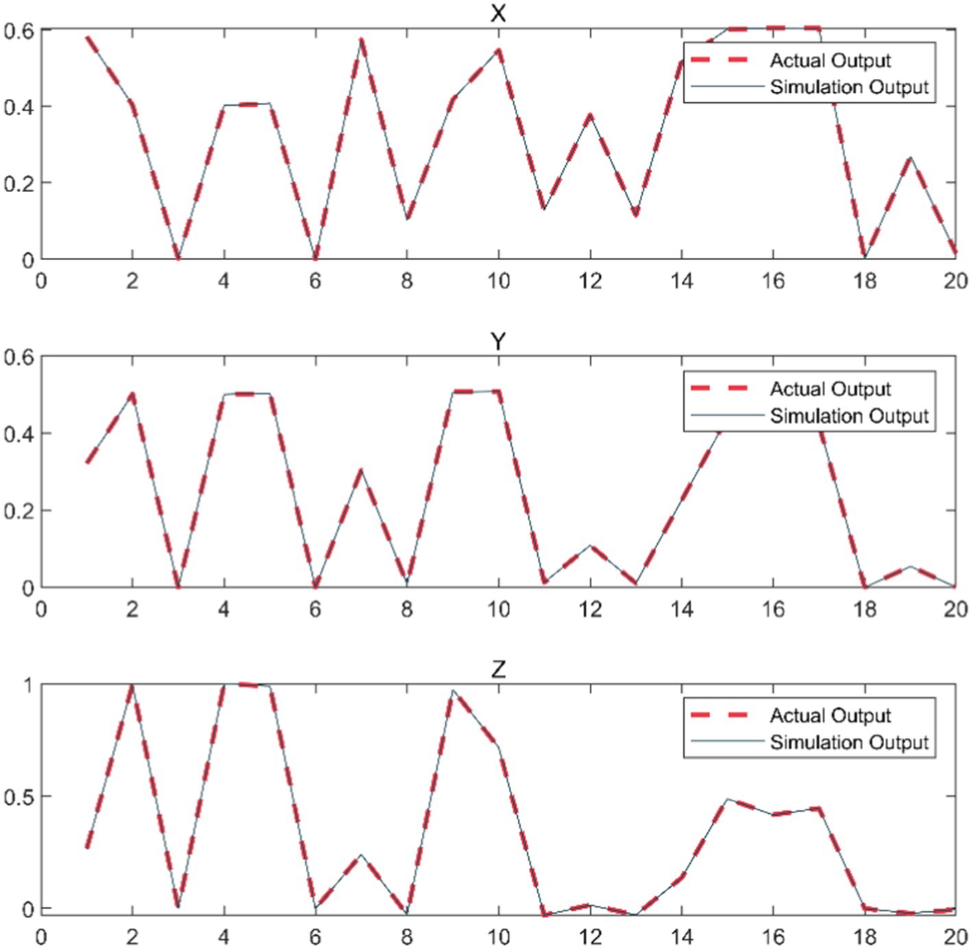
Figure 8. Comparison of end coordinate prediction results.
Additionally, this data-driven prediction method possesses stronger adaptability and flexibility compared to the traditional analytical method, and can handle the complex scenarios in practical applications more effectively.
4.2 Kinematics verification
Based on the characteristic parameters of the robotic arm links and the end effector spherical wrist, the correctness of both forward and inverse kinematics algorithms can be verified through curve acquisition in the driver software. The planner generates the trajectory curve of the robot end effector, and joint values are obtained through inverse kinematics. Then, spatial positions are calculated through forward kinematics, plotting numerous position points into a spatial curve. The degree of overlap between the two curves is compared.
Sinusoidal trajectories and spatial circular arc trajectories are separately applied to track trajectories using kinematic algorithms. As illustrated in Figures 9, 10, these are curves collected by the driver software.
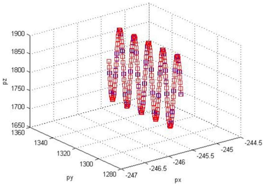
Figure 9. Sine tracking curve.
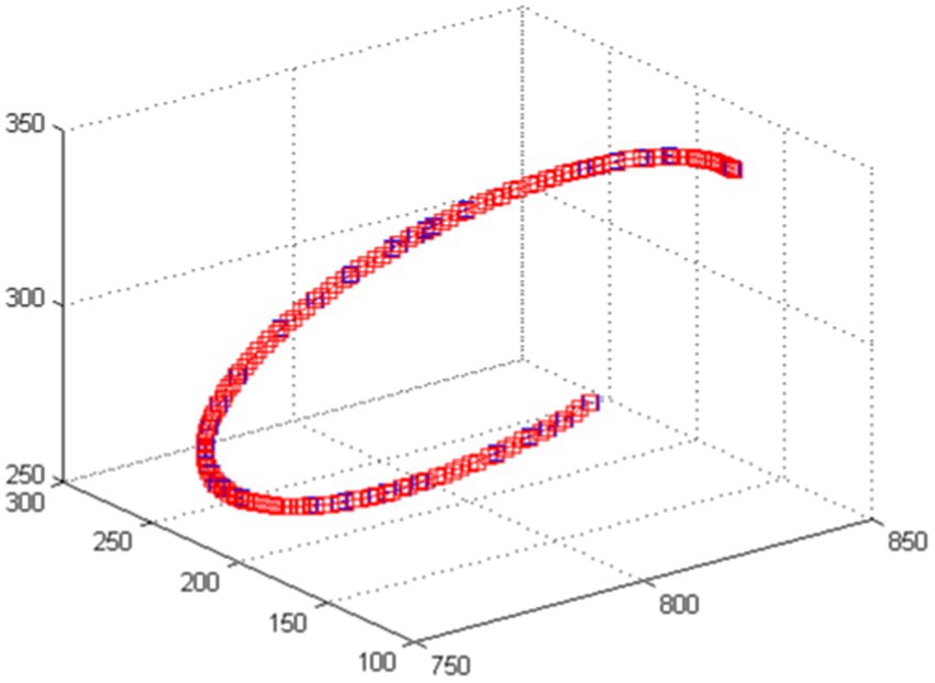
Figure 10. Circular arc trace curve.
4.3 Trajectory planning verification
The NURBS curve functions as a generalized parameter interpolator, maintaining a uniform feed rate for most of the interpolation process and ensuring that each interpolation point falls within a specified error range. As shown in Figure 11, the interpolator avoids sharp corners and feed-sensitive angles in the curve, thereby mitigating high-frequency components or frequencies matching the machine inherent frequency in the interpolation trajectory, reducing high jitter. In the trajectory planning method, a forward-looking module detects sharp corners of the NURBS curve. An acceleration-deceleration method then adjusts the feed rate at these corners to meet error requirements and accommodate the robot acceleration and deceleration capabilities.
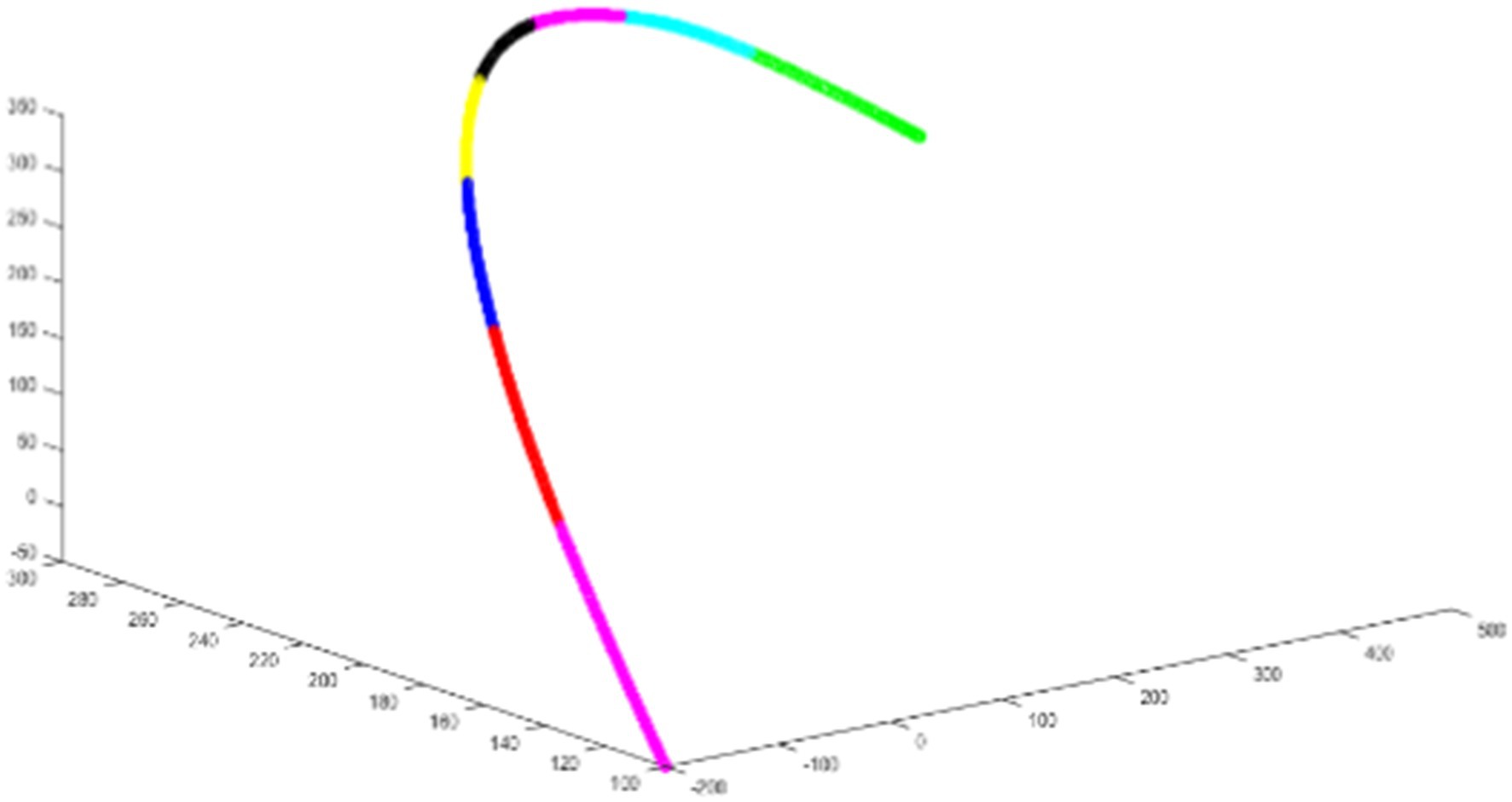
Figure 11. NURBS spline diagram.
4.4 Collision detection algorithm
To quickly verify the feasibility of the collision detection algorithm, we conducted simulation experiments using a two-degree freedom robot model for comparative research. As shown in Figure 12, the dashed line represents the simulation results of the unimproved observer (Equation 18). In contrast, the solid red and green lines represent the simulation results of the improved torque observer (Equation 20). The solid black line simulates the occurrence of a collision. It can be observed that after the collision occurs, the improved observer exhibits reduced overshoot and quick response speed.
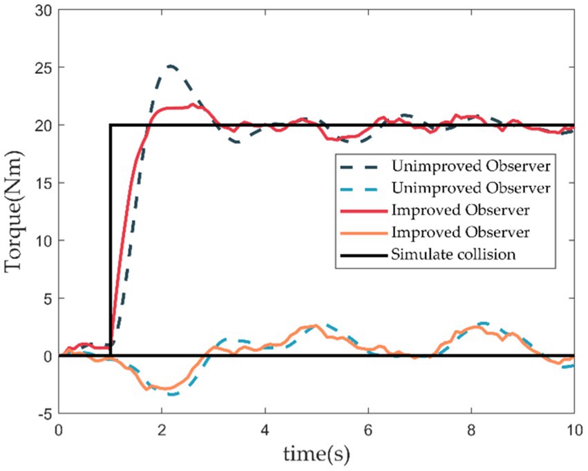
Figure 12. Collision detection simulation.
4.5 True machine verification
This paper conducts experiments on flexible control and trajectory planning using the medical dual-arm collaborative robot produced by Siasun Corporation. Figure 13A depicts the experimental results of drug dispensing by the medical assistance dual-arm robot.
(1) Opening the bottle cap: (demonstrated using preopened medication, placing the opened aluminum cap into a box)
a. The robot left arm grabs the bottle while the right arm grasps the bottle opener.
b. The left arm places the bottle in the specified position and visually checks the notch position. If the position is incorrect, the left arm rotates the bottle to a specific position. Subsequently, the right arm grabs the bottle opener and quickly presses down to remove the aluminum cap from the medication using pressure.
c. The right arm returns the bottle opener to its original position, while the left arm lifts the bottle and places the pressed aluminum cap into the collection box. A visual system is introduced here to confirm whether the bottle cap has been successfully opened. An error message is prompted if it is still attached to the bottle or the opener.
d. After disposing of the aluminum cap, the bottle is placed back in the specified position.
(2) Medication dispensing demonstration:
a. The right arm grabs the syringe, as shown in Figure 13B, while the left grabs the plunger.
b. The two arms cooperate to demonstrate liquid suction from the vial and inject the liquid into the bottle, as shown in Figure 13C.
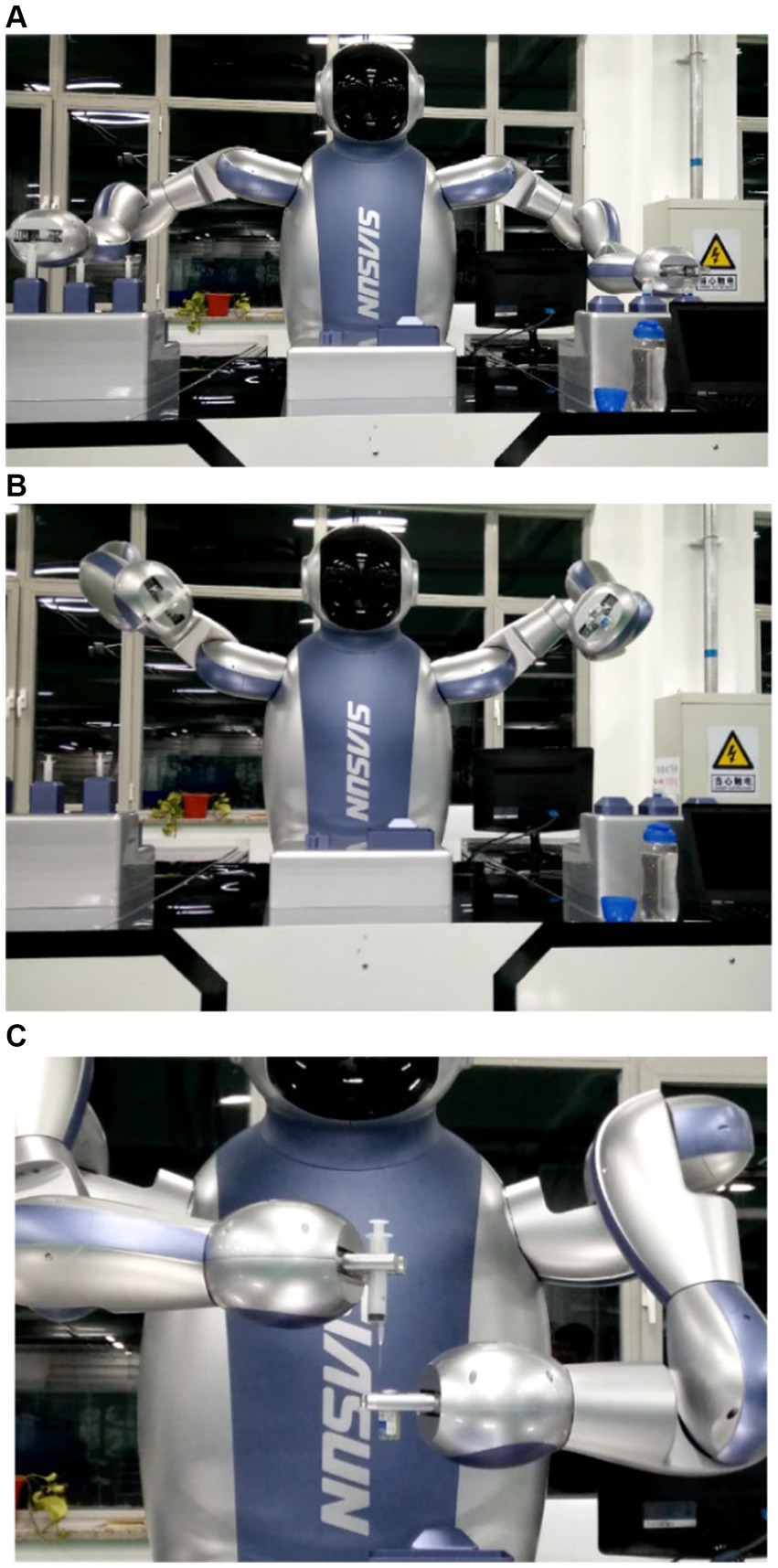
Figure 13. (A) Medical robot medicine dispensing. (B) Medical robot medicine dispensing. (C) Medical robot medicine dispensing.
5 Conclusion
This paper addresses the challenges of flexible control and trajectory planning in medical dual-arm collaborative robots. It proposes a neural network based kinematic solver as a universal approximator to resolve the kinematic problems of humanoid dual-arm robots while ensuring solution accuracy. Compared to other numerical and geometric methods for solving equation systems, the neural network based kinematic solver directly obtains reasonable solutions in the workspace when the number of unknowns exceeds the number of equations, providing a concise selection approach. Regarding trajectory planning, we propose a comprehensive interpolation scheme based on NURBS curve interpolation. The NURBS spline fitting method is employed to further smooth the interpolated feed curves, with repeated checks for chord error during interpolation to restrict it within a specified error range. Additionally, an improved second-order momentum torque observer is designed to accurately detect external collisions without external sensors. This observer operates without requiring arm acceleration as input, effectively avoiding interference and errors caused by acceleration. Optimized observer design significantly reduces system overshoot, thereby enhancing collision detection accuracy.
Data availability statement
The data supporting this study’s findings are available from the corresponding author upon reasonable request.
Author contributions
YX: Writing – original draft. XZ: Writing – original draft. YJ: Writing – original draft, Writing – review & editing. YW: Writing – review & editing. HY: Writing – review & editing.
Funding
The author(s) declare that financial support was received for the research, authorship, and/or publication of this article. This research was funded by Basic Research on Stress induced Bone Growth of Porous Titanium and Its Potential Application in Spinal Fusion Cages (Project No.: 2023JH2/101700136), Basic and Applied Research Project of Liaoning Provincial Science and Technology Planning.
Conflict of interest
The authors declare that the research was conducted in the absence of any commercial or financial relationships that could be construed as a potential conflict of interest.
Publisher’s note
All claims expressed in this article are solely those of the authors and do not necessarily represent those of their affiliated organizations, or those of the publisher, the editors and the reviewers. Any product that may be evaluated in this article, or claim that may be made by its manufacturer, is not guaranteed or endorsed by the publisher.
References
Anderson, R. J., and Spong, M. W. (1988). Hybrid impedance control of robotic manipulators. IEEE J. Robot. Aut. 4, 549–556. doi: 10.1109/56.20440
Angelidis, A., and Vosniakos, G. C. (2014). Prediction and compensation of relative position error along industrial robot end-effector paths. Int. J. Precis. Eng. Manuf. 15, 63–73. doi: 10.1007/s12541-013-0306-5
Aoyagi, S., Suzuki, M., Takahashi, T., Fujioka, J., and Kamiya, Y. (2012). Calibration of kinematic parameters of robot arm using laser tracking system: compensation for non-geometric errors by neural networks and selection of optimal measuring points by genetic algorithm. Int. J. Autom. Technol. 6, 29–37. doi: 10.20965/ijat.2012.p0029
Asada, H., Ma, Z. D., and Tokumaru, H. (1990). Inverse dynamics of flexible robot arms: Modeling and computation for trajectory control. J. Dyn. Sys., Meas., Control Jun 1990, 112: 177–185. doi: 10.1115/1.2896124
Cao, P., Gan, Y., and Dai, X. (2019). Model-based sensorless robot collision detection under model uncertainties with a fast dynamics identification. Int. J. Adv. Robot. Syst. 16:1729881419853713. doi: 10.1177/1729881419853713
Chalhoub, N. G., and Ulsoy, A. G. (1987). Control of a flexible robot arm: Experimental and theoretical results. J. Dyn. Sys., Meas., Control 109:4. doi: 10.1115/1.3143859
Culmer, P. R., Jackson, A. E., Makower, S., Richardson, R., Cozens, J. A., Levesley, M. C., et al. (2009). A control strategy for upper limb robotic rehabilitation with a dual robot system. IEEE-ASME T. Mech. 15, 575–585. doi: 10.1109/TMECH.2009.2030796
Dong, Y., and Ren, B. (2017). UDE-based variable impedance control of uncertain robot systems. IEEE Trans. Syst. Man. Cybern. Syst. 49, 2487–2498. doi: 10.1109/TSMC.2017.2767566
Han, L., Xu, W., Li, B., and Kang, P. (2019). Collision detection and coordinated compliance control for a dual-arm robot without force/torque sensing based on momentum observer. IEEE-ASME T. Mech. 24, 2261–2272. doi: 10.1109/TMECH.2019.2934141
Hogan, N. (1985). Impedance control: An approach to manipulation: Part II—Implementation. J. Dyn. Sys., Meas., Control 107, 8–16. doi: 10.1115/1.3140713
Ikeura, R., and Inooka, H. (1995). Variable impedance control of a robot for cooperation with a human. In Proceedings of 1995 IEEE international conference on robotics and automation.
Jin, L., Zheng, X., and Luo, X. (2022). Neural dynamics for distributed collaborative control of manipulators with time delays. IEEE/CAA J. Autom. Sin. 9, 854–863. doi: 10.1109/JAS.2022.105446
Kojima, H. (2002). Trajectory planning of CP control flexible robot arm using genetic algorithm. Nihon Kikai Gakkai Ronbunshū. C 14, 1784–1790. doi: 10.1299/kikaic.68.1784
Kojima, H., and Kibe, T. (2001). Residual vibration reduction control of a two-link flexible robot arm using optimal trajectory planning based on genetic algorithm. J. Robot. Soc. Japan 19, 905–912. doi: 10.7210/jrsj.19.905
Li, W., Han, Y., Wu, J., and Xiong, Z. (2020). Collision detection of robots based on a force/torque sensor at the bedplate. IEEE-ASME T. Mech. 25, 2565–2573. doi: 10.1109/TMECH.2020.2995904
Li, S., He, J., Li, Y., and Rafique, M. U. (2016). Distributed recurrent neural networks for cooperative control of manipulators: a game-theoretic perspective. IEEE Trans. Neural Netw. Learn. Syst. 28, 415–426. doi: 10.1109/TNNLS.2016.2516565
Liu, Y., Liu, X., Cai, G., and Chen, J. (2021). Trajectory planning and coordination control of a space robot for detumbling a flexible tumbling target in post-capture phase. Multibody Syst. Dyn. 52, 281–311. doi: 10.1007/s11044-020-09774-6
Mohammed, A., Schmidt, B., and Wang, L. (2017). Active collision avoidance for human–robot collaboration driven by vision sensors. Int. J. Comput. Integr. Manuf. 30, 970–980. doi: 10.1080/0951192X.2016.1268269
Niku, S. B. (2020). Introduction to robotics: Analysis, control, applications. Hoboken, NJ: John Wiley & Sons.
Pandey, M. D., and Zhang, X. (2012). System reliability analysis of the robotic manipulator with random joint clearances. Mech. Mach. Theory 58, 137–152. doi: 10.1016/j.mechmachtheory.2012.08.009
Popov, D., Klimchik, A., and Mavridis, N. (2017) Collision detection, localization & classification for industrial robots with joint torque sensors. 2017 26th IEEE international symposium on robot and human interactive communication (RO-MAN).
Sharifi, M., Zakerimanesh, A., Mehr, J. K., Torabi, A., Mushahwar, V. K., and Tavakoli, M. (2021). Impedance variation and learning strategies in human–robot interaction. IEEE Trans. Cybern. 52, 6462–6475. doi: 10.1109/TCYB.2020.3043798
Sun, T., Peng, L., Cheng, L., Hou, Z. G., and Pan, Y. (2019). Stability-guaranteed variable impedance control of robots based on approximate dynamic inversion. IEEE Trans. Syst. Man. Cybern. Syst. 51, 4193–4200. doi: 10.1109/TSMC.2019.2930582
Venanzi, S., and Parenti-Castelli, V. (2005). A new technique for clearance influence analysis in spatial mechanisms. J. Mech. Des. 127, 446–455. doi: 10.1115/1.1867512
Wu, Q., Li, M., Qi, X., Hu, Y., Li, B., and Zhang, J. (2019). Coordinated control of a dual-arm robot for surgical instrument sorting tasks. Robot. Auton. Syst. 112, 1–12. doi: 10.1016/j.robot.2018.10.007
Yang, W., Li, S., Li, Z., and Luo, X. (2023). Highly accurate manipulator calibration via extended Kalman filter-incorporated residual neural network. IEEE Trans. Industr. Inform. 19, 10831–10841. doi: 10.1109/TII.2023.3241614
Yu, X., He, W., Li, Y., Xue, C., Li, J., Zou, J., et al. (2019). Bayesian estimation of human impedance and motion intention for human–robot collaboration. IEEE Trans. Cybern. 51, 1822–1834. doi: 10.1109/TCYB.2019.2940276
Zeng, L., and Bone, G. M. (2013). Design of elastomeric foam-covered robotic manipulators to enhance human safety. Mech. Mach. Theory 60, 1–27. doi: 10.1016/j.mechmachtheory.2012.09.010
Zhong, F., Wang, Y., Wang, Z., and Liu, Y. H. (2019). Dual-arm robotic needle insertion with active tissue deformation for autonomous suturing. IEEE Robot. Autom. Lett. 4, 2669–2676. doi: 10.1109/LRA.2019.2913082
Further reading
Amersdorfer, M., and Meurer, T. (2022). Equidistant tool path and cartesian trajectory planning for robotic machining of curved freeform surfaces. IEEE Trans. Autom. Sci. Eng. 19, 3311–3323. doi: 10.1109/TASE.2021.3117691
Chen, T., Li, S., Qiao, Y., and Luo, X. (2024). A robust and efficient Ensemble of Diversified Evolutionary Computing Algorithms for accurate robot calibration. IEEE Trans. Instrum. Meas. 73:7501814. doi: 10.1109/TIM.2024.3363783
Jiang, Y., Wu, Y., Wu, X., and Zhao, B. (2023). Research on collision detection of collaborative robot using improved momentum-based observer. 2023 IEEE IAS global conference on emerging technologies (glob con ET).
Kojima, H., and Kibe, T. (2001). Optimal trajectory planning of a two-link flexible robot arm based on genetic algorithm for residual vibration reduction. Proceedings 2001 IEEE/RSJ International conference on intelligent robots and systems. Expanding the Societal Role of Robotics in the Next Millennium (Cat. No.01CH37180).
Li, Z., Li, S., Bamasag, O. O., Alhothali, A., and Luo, X. (2022). Diversified regularization enhanced training for effective manipulator calibration. IEEE Trans. Neural Netw. Learn. Syst. 34, 8778–8790. doi: 10.1109/TNNLS.2022.3153039
Li, Z., Li, S., Francis, A., and Luo, X. (2022). A novel calibration system for robot arm via an open dataset and a learning perspective. IEEE Trans. Circuits. Syst. II Express Briefs 69, 5169–5173. doi: 10.1109/TCSII.2022.3199158
Li, Z., Li, S., and Luo, X. (2021). An overview of calibration technology of industrial robots. EEE/CAA J. Autom. Sin. 8, 23–36. doi: 10.1109/JAS.2020.1003381
Lismonde, A., Sonneville, V., and Brüls, O. (2019). A geometric optimization method for the trajectory planning of flexible manipulators. Multibody Syst. Dyn. 47, 347–362. doi: 10.1007/s11044-019-09695-z
Luo, X., Yuan, Y., Chen, S., Zeng, N., and Wang, Z. (2020). Position-transitional particle swarm optimization-incorporated latent factor analysis. IEEE Trans. Knowl. Data Eng. 34, 3958–3970. doi: 10.1109/TKDE.2020.3033324
Meng, D., Lu, W., Xu, W., She, Y., Wang, X., Liang, B., et al. (2018). Vibration suppression control of free-floating space robots with flexible appendages for autonomous target capturing. Acta Astronaut. 151, 904–918. doi: 10.1016/j.actaastro.2018.07.044
Meng, D., Wang, X., Xu, W., and Liang, B. (2017). Space robots with flexible appendages: dynamic modeling, coupling measurement, and vibration suppression. J. Sound Vib. 396, 30–50. doi: 10.1016/j.jsv.2017.02.039
Oke, G., and Istefanopulos, Y. (2001). Gradient-descent based trajectory planning for regulation of a two-link flexible robotic arm. 2001 IEEE/ASME International Conference on Advanced Intelligent Mechatronics. Proceedings (Cat. No.01TH8556).
Palleschi, A., Mengacci, R., Angelini, F., Caporale, D., Pallottino, L., De Luca, A., et al. (2020). Time-optimal trajectory planning for flexible joint robots. IEEE Robot. Autom. Lett. 5, 937–944. doi: 10.1109/LRA.2020.2965861
Peña Fernández, C. A. (2023). An ergodic selection method for kinematic configurations in autonomous, flexible mobile systems. J. Intell. Robot. Syst. 109:11. doi: 10.1007/s10846-023-01933-z
Qiu, Z., and Zhang, W. (2019). Trajectory planning and diagonal recurrent neural network vibration control of a flexible manipulator using structural light sensor. Mech. Syst. Signal Process. 132, 563–594. doi: 10.1016/j.ymssp.2019.07.014
Ren, X., Li, Z., Zhou, M., and Hu, Y. (2023). Human intention-aware motion planning and adaptive fuzzy control for a collaborative robot with flexible joints. IEEE Trans. Fuzzy Syst. 31, 2375–2388. doi: 10.1109/TFUZZ.2022.3225660
Tian, Y., Yue, X., Wang, L., and Feng, Y. (2023). Vibration suppression of collaborative robot based on modified trajectory planning. Ind. Robot. 50, 45–55. doi: 10.1108/IR-01-2022-0017
Wang, G., Li, W., Jiang, C., Zhu, D., Li, Z., Xu, W., et al. (2022). Trajectory planning and optimization for robotic machining based on measured point cloud. IEEE Trans. Robot. 38, 1621–1637. doi: 10.1109/TRO.2021.3108506
Weingartshofer, T., Hartl-Nesic, C., and Kugi, A. (2023). Automatic and flexible robotic drawing on complex surfaces with an industrial robot. IEEE Trans. Control Syst. Technol. 99, 1–14. doi: 10.1109/TCST.2023.3345209
Wu, H., Sun, F., Sun, Z., and Wu, L. (2004). Optimal trajectory planning of a flexible dual-arm space robot with vibration reduction. J. Intell. Robot. Syst. 40, 147–163. doi: 10.1023/B:JINT.0000038946.21921.c7
Yoshida, Y., and Tanaka, M. (1994). Trajectory control of two-link flexible arm: experiments using joint actuators and active mass damper. Trans. Jpn. Soc. Mech. Eng. C 60, 2310–2315. doi: 10.1299/kikaic.60.2310
Keywords: medical two-arm robot, momentum observer, motion control, trajectory planning, FKP
Citation: Xie Y, Zhao X, Jiang Y, Wu Y and Yu H (2024) Flexible control and trajectory planning of medical two-arm surgical robot. Front. Neurorobot. 18:1451055. doi: 10.3389/fnbot.2024.1451055
Edited by:
Xin Luo, Chinese Academy of Sciences (CAS), ChinaReviewed by:
Bin Zhi Li, Chinese Academy of Sciences (CAS), ChinaTinghui Chen, Chongqing University of Posts and Telecommunications, China
Copyright © 2024 Xie, Zhao, Jiang, Wu and Yu. This is an open-access article distributed under the terms of the Creative Commons Attribution License (CC BY). The use, distribution or reproduction in other forums is permitted, provided the original author(s) and the copyright owner(s) are credited and that the original publication in this journal is cited, in accordance with accepted academic practice. No use, distribution or reproduction is permitted which does not comply with these terms.
*Correspondence: Hailong Yu, MTk1NTQxNjM1OUBxcS5jb20=