 Peng Ziping
 Zheng Jishi
 Cai Qiushen
95% of researchers rate our articles as excellent or good
Learn more about the work of our research integrity team to safeguard the quality of each article we publish.
Find out more
ORIGINAL RESEARCH article
Front. Mech. Eng. , 18 February 2025
Sec. Solid and Structural Mechanics
Volume 11 - 2025 | https://doi.org/10.3389/fmech.2025.1467079
High-voltage cable terminal lead seals may develop defects such as holes, cracks, or delamination due to substandard installation quality or external forces during operation. Owing to the large curvature of the lead seal surface, using conventional ultrasonic probes for direct contact with the surface results in low efficiency in detecting lead seal defects and yields a low signal-to-noise ratio for defect echo signals. To address the ineffective detection of lead seal defects, a non-destructive detection method based on ultrasonic phased array flexible water bag coupling is proposed. This method employs an ultrasonic phased array probe and a flexible water bag coupling device to form a lead seal defect detection system. Firstly, a simulation model for lead seal defects is established using COMSOL finite element simulation software to design and optimize the detection parameters of the ultrasonic phased array probe. Detection experiments are then conducted on three typical artificially fabricated defect samples. The results indicate that different beam deflection angles and focal distances of the probe affect the detection outcomes. Through ultrasonic phased array probe sector scan (S-scan) images and ultrasonic pulse echo reflection (A-scan) images, both qualitative analysis and quantitative measurement of lead seal defects can be achieved. This method demonstrates that the ultrasonic phased array terminal lead seal defect detection technique, utilizing a flexible water bladder coupled probe, can quickly and intuitively identify lead seal defects, providing a new approach for defect detection in high-voltage cable terminal lead seals.
As the load on China’s power grid continues to grow and urbanization accelerates, the demand for safer power cables that occupy less land is increasing (Zhou et al., 2014; Yang et al., 2024; Yang et al., 2021a; Yang et al., 2021b; Hu et al., 2014). The lead seal of cable terminals is a key structure that connects the metal sheath and cable accessories, ensuring a good grounding system and providing sealing and waterproofing functions (Luo et al., 2011; Wu, 2011; Shen, 1983). However, the quality of construction and fatigue damage caused by stress changes during operation can result in defects such as air holes, cracking, and partial or complete delamination at the interface between the lead seal and the aluminum sheath. These defects can cause trip faults in high-voltage cable lines, jeopardizing the safe operation of the power grid (Cao Jingxing et al., 2018; Lu, 2017). Therefore, there is an urgent need to develop methods for accurately and quickly detecting defects in high-voltage cable terminal lead seals.
Various techniques, such as partial discharge detection, infrared detection, electric field distribution detection, and radiographic detection, are widely used to diagnose defects in power cable accessories (Luo et al., 2003; Wu, 2005). Partial discharge is detection is particularly effective for identifying insulation defects, such as air gaps and partial discharge sources; however, it cannot directly detect structural issues like physical damage or mechanical defects in cable terminals. Infrared testing excels at assessing surface conditions and temperature changes but has limitations in detecting internal defects and environmental effects. Electric field distribution detection primarily evaluates the electric field distribution around cable terminals or insulators, focusing on surface electric fields or electric field abnormalities near the surface. Additionally, the radiation generated by radiographic testing poses certain safety hazards to operators and the environment.
These methods have several issues, including high detection condition requirements, complex operations, lengthy detection times, unclear imaging, and low detection accuracy, rendering them ineffective for detecting defects in cable terminal lead seals. The detection of defects in high-voltage cable terminal lead seals is still in the exploratory stage. Currently, Junping Cao and others have adopted eddy current testing methods to identify defects in high-voltage cable terminal lead seals, achieving good results in detecting cracking defects in lead seals. However, due to the limitations in eddy current detection depth, it is not possible to effectively detect internal defects within the lead seals or defects between the lead seals and the aluminum sheaths (Cao Junping et al., 2018; Cao et al., 2020). The limitations of the current testing methods are summarized in Table 1.
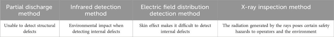
Table 1. Limitations of current testing methods.
At present, ultrasonic non-destructive testing (NDT) is the primary method for identifying internal defects in complex structures. The application of ultrasonic phased array NDT for detecting defects in high-voltage cable terminal lead seals meets significant engineering demand. Compared to traditional ultrasonic NDT, ultrasonic phased array exhibits outstanding advantages, including a wide scanning range, clear defect images, distinct defect echoes, high detection efficiency, and accurate defect localization, making it particularly effective for detecting defects in curved structures (Wei et al., 2021; Jiannan, 2018; Howard and Cegla, 2017). Wentao Li and others introduced a one-transmit-one-receive array ultrasonic detection method using dual-array ultrasonic transducers, significantly enhancing detection capability and efficiency over single-crystal ultrasonic transducers (Wentao and Zhenggan, 2020). HABERMEHL from Olympus developed a curved array probe capable of achieving vertical ultrasonic beam incidence by adjusting the curvature center of the R area in CFRP (Habermehl et al., 2009). Additionally, other researchers have proposed a flexible array probe that can be attached to the concave or convex surfaces of different curvatures in the R area of CFRP for defect detection, albeit at a higher cost (Phoenix Inspection Systems Limited, 2013). WANG Xin and others improved the signal-to-noise ratio and echo coefficient of echo signals by controlling the time delay and amplitude of each ultrasonic array sensor. This approach can eliminate the impact of the geometric shapes of the components on defect detection, enabling focused detection of gun barrels using ultrasonic guided waves and demonstrating significant potential for defect detection in curved components (Xin et al., 2019).
This paper proposes a method based on ultrasonic phased array flexible water bag coupling for terminal lead seal detection, aiming to address the issue of ineffective defect detection in lead seals due to large surface curvature and unevenness. First, the propagation characteristics and behavior of sound waves within lead seals were analyzed using COMSOL finite element simulation software. Next, the effects of different beam deflection angles and focal lengths of ultrasonic phased array probes on the detection of cable terminal lead seal defects were studied. Then, an ultrasonic phased array flexible coupling probe was fabricated, and targeted simulation experiments were conducted to verify the feasibility of the proposed method.
The ultrasonic phased array probe is composed of multiple mutually independent piezoelectric wafers arranged and combined in an orderly manner according to specific spacing, shapes, and sizes. Each wafer is referred to as an array element. The detection principle involves controlling acoustic beam deflection and acoustic beam focusing.
In acoustic beam deflection control, the delay time between adjacent array elements of the ultrasonic phased array is the same, allowing the array elements at one end to be excited first, followed by a sequential increase in the delay excitation time at equal intervals. When the excitation times of the various array elements change in a regular manner, the wavefront and the linear array will form a certain angle. At this point, the sound fields generated by the array will superimpose and enhance in the deflection direction, thus achieving the goal of deflecting the sound beam.
Acoustic beam focusing control manages the excitation of each array element by adjusting the delay times of the array elements. Excitation is carried out successively from both ends toward the center position, with the array elements closer to the center having longer delay times. This allows the wavefronts synthesized by the acoustic beams to superimpose and converge at a center of curvature, which is the focal point of the phased array.
By combining acoustic beam deflection and focusing, both deflection and focusing of the acoustic beam can be achieved simultaneously. By changing the excitation times of the array elements at both ends, the amplitudes and phases of the ultrasonic signals are superimposed at the predetermined focal position, while multiple ultrasonic signals cancel each other out in irrelevant areas, significantly reducing interference. The scanning principle is illustrated in Figure 1.
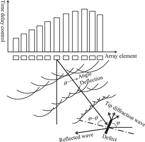
Figure 1. Deflection focusing diagram of ultrasonic phased array system.
In this paper, the focusing of the ultrasonic phased array is achieved through the spherical and linear timing relationships of each array element. The beam can be focused within a given range and propagated at a specific azimuth angle. The relative position of the defect in the cable terminal lead seal and the detection sound source of the ultrasonic probe significantly affects the detection results. Assuming the deflection angle of the phased array ultrasonic beam is θ, the inclination angle of the defect is φ, and the incidence angle of the ultrasonic beam at the center of the defect is θ-φ. The focusing delay can be calculated using the following formula (Azar et al., 2000):
In the formula, F is the distance from the center of the array to the focal point; tn is the delay time of the nth array element; t0 is a constant set to ensure that tn is positive; C is the wave speed; and d is the spacing between array elements.
According to Huygens’ principle, the analytical expression for the sound pressure distribution for a single array element is (Wooh and Shi, 1998):
where r is the distance from the focal point to the center of the phased array transducer; ωis the angular frequency; j is the imaginary unit; and k is the wave number.
The sound pressure of the reflected wave at the center point of the transducer can be expressed as (Sai et al., 2016):
where rLL is the sound pressure reflection coefficient at the interface between air and the specimen; p0 is the defect echo sound pressure when the ultrasonic wave is incident perpendicularly; DL is the directivity coefficient of the sound beam; kL = 2π/λ is the wave vector, and λ is the wavelength of the sound wave.
When φ≈θ, meaning the main beam axis is perpendicular to the defect plane, the reflection sound pressure of the defect is at its maximum, and the ultrasonic transducer receives the highest defect echo sound pressure.
High-voltage cable terminals are complex curved structures composed of aluminum sheaths, lead seals, heat-shrink tubes, and tail pipes. The propagation characteristics of sound waves within these structures are intricate. To verify the effectiveness of the lead seal defect detection scheme, a two-dimensional simulation model for detecting lead seal defects in high-voltage cable terminals was established based on the Time Domain Finite Difference (TDFD) method. This model was used to analyze the propagation characteristics and behavior of ultrasonic waves in typical lead seal defects, providing guidance for practical detection.
As shown in Figure 2, both internal defects and interlayer defects are incorporated into the lead seal. The internal defect is located 1 cm from the upper surface of the lead seal, while the interlayer defect is situated at the bonding interface between the lead seal and the aluminum sheath. The density of the lead seal is approximately 11.34 g/cm³, its Young’s modulus is 17 GPa, and its Poisson’s ratio is 0.42. The aluminum sheath has a density of about 2.7 g/cm³, a Young’s modulus of 70 GPa, and a Poisson’s ratio of 0.33. The mesh size of the high-voltage cable terminal lead seal simulation model is a minimum of 0.2 mm, the simulation time interval is 0.02 μs, and the total simulation time is 15 μs. The excitation load for the array elements is a pressure load with a center frequency of 5 MHz. The ultrasonic transmission parameters of the materials involved in the testing of lead seal defects are shown in Table 2.
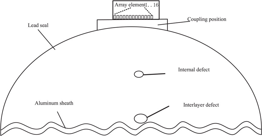
Figure 2. Simulation model of cable terminal lead seal.
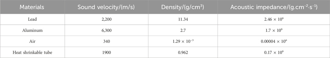
Table 2. Ultrasonic transmission parameters.
Based on the specimen size, defect size, and parameters of the ultrasonic transducer position, the main parameters of an array ultrasonic transducer, such as center frequency, number of array elements, and array element spacing, were designed. The designed parameters of the transducer array elements were then adjusted and optimized according to the sound field distribution. The main parameters of the array ultrasonic transducer, specifically designed for detecting defects in high-voltage cable terminal lead seals, are shown in Table 3.
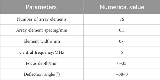
Table 3. Parameters of ultrasonic phased array transducer.
To assess the influence of different beam deflection angles on defect detection, the deflection angles were set to 0°, −10°, −20°, and −30°, respectively. The effect of the beam deflection angle on the detection results of lead seal defects was studied by analyzing the defect echo amplitude obtained through delay stacking. The delay times for each array element are illustrated in Figure 3. At a deflection angle of 0°, the delay times for elements 1 to 16 are 0, with elements 8 and 9 exhibiting the longest delays, which are symmetrically distributed. As the delay times for elements 1 to 16 increase, so do the deflection angles; longer delays correspond to greater angle deflections. The transient distribution of the total sound pressure field at varying deflection angles is shown in Figure 4, while the defect signals resulting from delay stacking are presented in Figure 5. The defect is positioned on the main axis of the sound beam at a 0° deflection angle. As the deflection angle increases, the beam focus gradually shifts away from the defect. When the deflection angle is less than −20°, the sound wave is barely reflected, causing the defect echo amplitude to approach 0. Therefore, for effective lead seal defect detection, it is crucial to dynamically adjust the beam deflection angle in real-time according to the delay rules, enabling thorough and comprehensive scanning of defects from all angles.
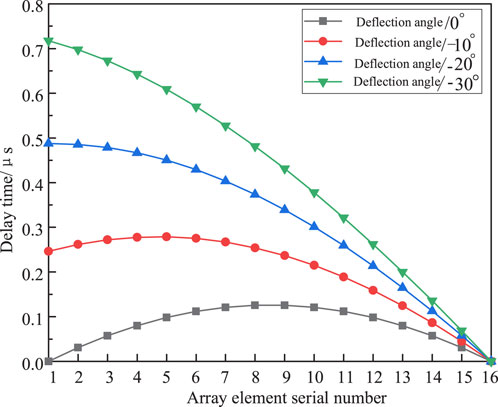
Figure 3. Delay time of array elements at different beam deflection angles.
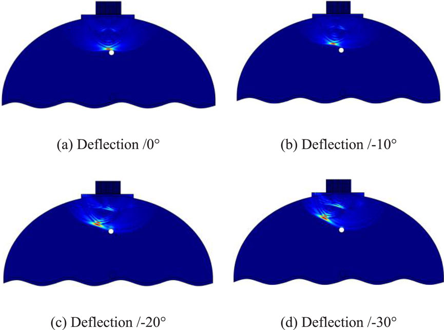
Figure 4. Transient distribution of total sound pressure field at different beam deflection angles. (A) Deflection/0°. (B) Deflection/-10°. (C) Deflection/-20°. (D) Deflection/-30°.
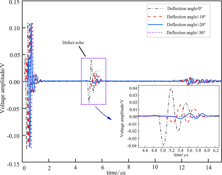
Figure 5. Defect echo at different beam deflection angles.
To compare the effect of different focusing depths on defect detection, focusing depths were set at 4 mm, 7 mm, 10 mm, and 13 mm, with the upper surface of the defect located at the 13 mm position. The transient distribution of the total sound pressure field at these focusing depths is shown in Figure 6, while the defect signals obtained through delay stacking are presented in Figure 7. It can be observed that as the focusing depth approaches the defect location, the focus of the sound wave also gradually moves closer to the defect, resulting in clearer and more distinct defect echoes. Conversely, when the focusing depth is shallower--meaning the focus is further from the defect--the defect echo appears more cluttered. Therefore, in practical lead seal defect detection, it is essential to adjust the focusing depth to enhance the clarity of the defect image and make the defect echo more distinct, aiding in accurately determining the defect’s location.
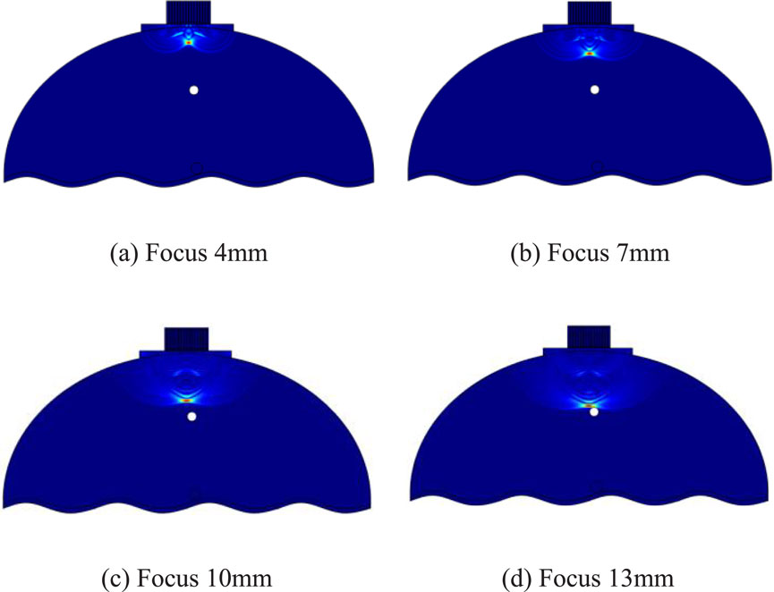
Figure 6. Transient distribution of total sound pressure field at different focusing depths. (A) Focus 4 mm, (B) Focus 7 mm, (C) Focus 10 mm, (D) Focus 13 mm.

Figure 7. Defect echo with different focusing depths.
Simulation models of defects at different positions were established, and corresponding delay processing was performed for each array element of the ultrasonic probe. The received defect echo signals were extracted and plotted, as shown in Figure 8. The internal defect echo was received by the probe at 5.4 μs, while the interlayer defect echo was received at 10.3 μs, which corresponds well to the expected defect positions in the simulation model. The simulation results demonstrate the effectiveness of this detection method in identifying defects located at various positions within the lead seal, thus verifying both the accuracy of the detection method and the selected detection parameters.

Figure 8. Echo of defects at different positions.
Figure 9 illustrates common terminal lead seal failures in high-voltage power cables during grid operations.
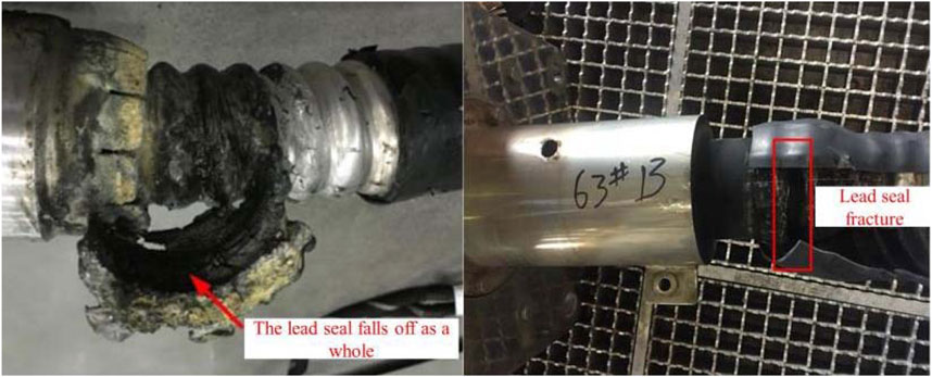
Figure 9. High-voltage cable lead seal failures.
To accurately simulate defects in cable terminal lead seals, three types of artificial defect samples were created for this experiment: a lead seal internal defect sample, a lead seal interlayer defect sample, and a sample with both internal and interlayer defects simultaneously. Figure 10 shows the appearance of the lead seal sample. Figure 11 illustrates all types of lead seal defects studied in HV cable terminals and indicates their locations.
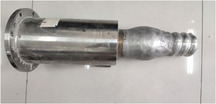
Figure 10. Cable terminal lead seal test sample.
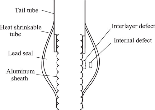
Figure 11. Typical defects of cable terminal lead seal.
When using a planar ultrasonic probe, effectively detecting internal defects within the lead seal can be challenging. To address the surface characteristics of high-voltage cable terminal lead seals, this study employs an ultrasonic phased array probe with a flexible water bladder for defect detection.
Due to the large curvature of the lead seal surface on the high-voltage cable terminal, the ultrasonic phased array probe is placed directly on the lead seal surface for defect detection. However, this positioning can create a large air gap between the probe and the lead seal, leading to substantial attenuation of the ultrasonic waves in the air. When testing the terminal lead seal specimen, the probe cannot effectively couple with the lead seal surface, and simply applying a large amount of couplant does not adequately resolve this issue.
The traditional ultrasonic water immersion method employs water as a couplant, placing both the ultrasonic testing probe and the testing specimen in a water tank for defect detection. However, using this method to detect lead seal defects may damage the terminal lead seal structure and is not suitable for on-site testing because of its significant limitations.
To address this problem, an ultrasonic phased array flexible coupling device has been designed. The ultrasonic phased array flexible water bladder coupling device is shown in Figure 12. It consists of four parts: an ultrasonic phased array probe, an aluminum shell, a water injection hole, and a silicone rubber membrane. This flexible water bladder coupling device is sealed, and water is used as a coupling agent and is injected into the water bladder through the water injection hole. The flexible membrane can bulge during the injection process.
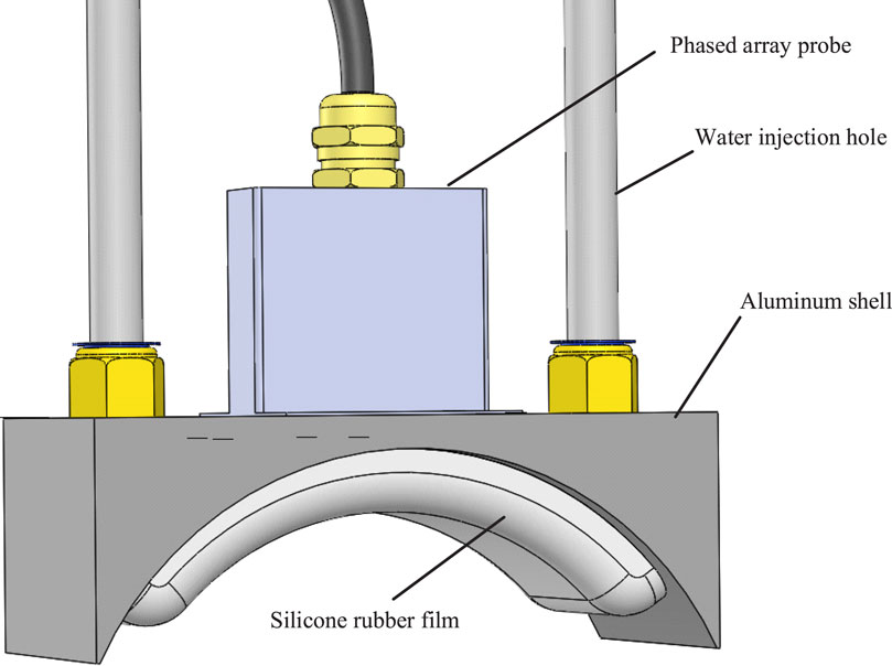
Figure 12. Ultrasonic phased array flexible water bag coupling device.
When injecting the coupling agent into the flexible water bladder, attention should be paid to avoiding air bubbles in the water bladder, as they can cause significant attenuation of the ultrasonic waves and lead to misjudgment in defect detection. Therefore, the coupling device is immersed in water to ensure it is filled and sealed, preventing any air bubbles from entering.
The experimental platform for ultrasonic phased array flexible coupling detection of cable terminal lead seal defects is illustrated in Figure 13. During the experiment, the flexible probe filled with the coupling agent is placed directly on the surface of the lead seal, achieving effective coupling while significantly reducing ultrasonic attenuation. This setup improves both detection efficiency and accuracy. The reflected signals are received by the same waveguide and transmitted to a computer. After data sorting and analysis, the reflected signals are converted into waveforms and images for display on the computer.
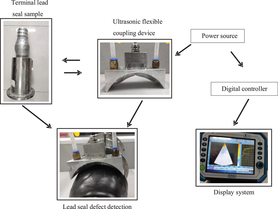
Figure 13. Ultrasonic flexible coupling lead seal defect detection platform.
First, an ultrasonic phased array scan was performed on a high-voltage cable terminal lead seal sample without defects using the flexible coupling device. Figure 14A shows the sector scan (S-scan) image, with the scan range set from −25° to +25°. In the S-scan, deeper colors in the image indicate higher echo amplitudes, suggesting greater acoustic impedance differences between the two media. Figure 14B presents the pulse-echo (A-scan) image taken at the central red line of the sector scan image. The horizontal axis represents the echo detection depth, while the vertical axis indicates the echo amplitude percentage, expressed as the ratio of the echo amplitude to its maximum value. Figure 14C displays another ultrasonic pulse-echo (A-scan) image, providing a detailed representation of the ultrasonic signal at the central red line of the sector scan image. The A-scan offers crucial information about the depth and amplitude of detected echoes within the lead seal.
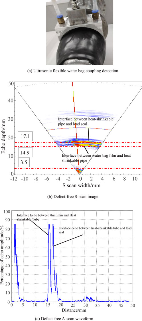
Figure 14. Lead seal defect-free flexible coupling detection. (A) Ultrasonic flexible water bag coupling detection. (B) Defect-free S-scan image. (C) Defect-free A-scan waveform.
In Figure 14B, a bright area near the probe is observed, primarily due to the detection blind zone within 1 mm of the object’s surface and the combined effect of partial wave reflections as the ultrasound enters the object. No highlighted bright areas or echoes are observed between 3.5 mm and 14.9 mm. A highlighted bright area and high echo amplitude are noted at a depth of 14.9 mm, indicating the interface between the flexible water bag membrane and the heat-shrink tube. Another highlighted bright area and high echo amplitude are seen at 17.1 mm, marking the interface between the heat-shrink tube and the lead seal. The measured thickness of the heat-shrink tube is 2 mm, which matches the actual thickness.
Due to the lead seal being wrapped in a heat-shrink tube, the ultrasound must penetrate the heat-shrink tube to reach the interior of the lead seal when using phased array ultrasonic equipment for detection. The attenuation within the heat-shrink tube is relatively high, necessitating an increase in the excitation of the ultrasonic signal to achieve clearer S-scan and A-scan imaging. Using the ultrasonic flexible coupling device to test the terminal lead seal with internal defects, the phased array ultrasonic detection images are shown in Figures 15A,B. In the S-scan image at 25.2 mm, a distinct highlighted bright area is observed. Combined with the A-scan echo, it can be determined that the defect is located within the lead seal.
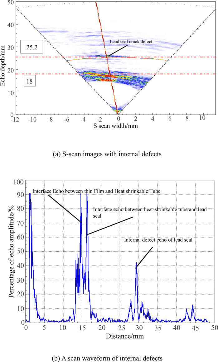
Figure 15. Flexible coupling detection of internal defects in the lead seal. (A) S-scan images with internal defects. (B) A scan waveform of internal defects.
When defects are present in both the internal and interlayer positions of the cable terminal lead seal sample, two distinct highlighted bright areas are clearly visible in the internal section of the S-scan image. By comparing with the A-scan waveform, it can be determined that the two defect images correspond to interlayer and internal defects, respectively. The defect images are clearly delineated, indicating that when multiple types of defects exist within the cable terminal lead seal, the ultrasonic phased array flexible coupling detection method can effectively distinguish between different defect locations, resulting in a high recognition rate.
In the phased array ultrasonic S-scan image shown in Figure 16A, the interface between the flexible water bladder film and the heat-shrink tube, as well as the interface between the heat-shrink tube and the lead seal, are clearly imaged. Figure 16B showing the imaging positions are consistent with those in Figures 14A, 15A. A defect image appears below the second interface, at approximately 32.5 mm, with clear and distinct imaging. The defect type can be easily identified based on its location, leading to a high defect recognition rate.
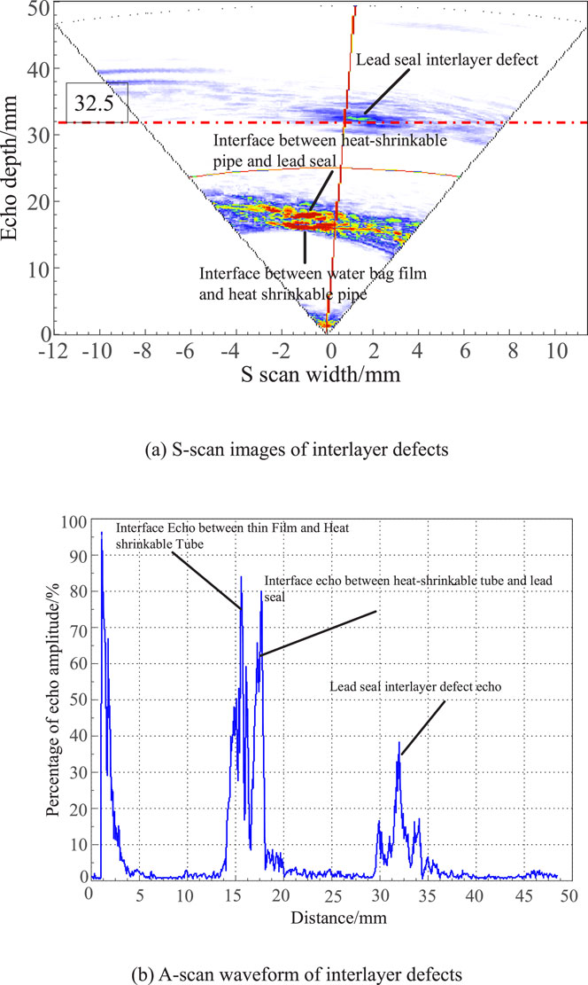
Figure 16. Flexible coupling detection of interlayer defects in lead seals. (A) S-scan images of interlayer defects. (B) A-scan waveform of interlayer defects.
When defects are present in both the internal and interlayer positions of the cable terminal lead seal sample, as shown in Figure 17, two distinct highlighted bright areas are clearly observed in the internal region of the S-scan image. By comparing with the A-scan waveform, it can be determined that these two defect images correspond to interlayer defects and internal defects, respectively. The defect images are clearly delineated, indicating that when multiple types of defects exist within the cable terminal lead seal, the ultrasonic phased array flexible coupling detection method can effectively distinguish between different defect locations, achieving a high recognition rate.
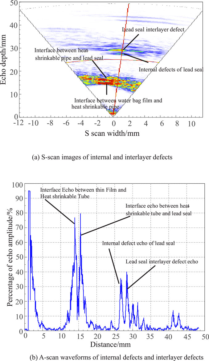
Figure 17. Flexible coupling detection of internal defects and interlayer defects in lead seals. (A) S-scan images of internal and interlayer defects. (B) A-scan waveforms of internal defects and interlayer defects.
(1) The focusing depth and beam deflection angle of the phased array ultrasonic probe significantly affect the accuracy of defect detection. As the deflection angle increases, the focal position of the sound beam gradually moves away from the defect, leading to a decrease in the amplitude of the defect echo. The farther the focal position is from the defect, the greater the noise becomes in the defect echo, which affects defect judgment. Therefore, the actual defect location can be determined by analyzing the position of the defect echo.
(2) In this paper, a flexible water bladder coupling ultrasonic detection method is employed to perform phased array ultrasonic sector scanning on the lead seal defects within cable terminals. This method effectively detects defects at various positions within the lead seal, providing clear imaging and distinct echoes of the defects. Moreover, it facilitates the quantitative determination of the location and size of the defects.
(3) This study also suggests that by controlling the signal delay of the array elements, the focusing direction and depth can be adjusted, enabling the detection of defects in the cable terminal lead seal with minimal or no probe movement. By modifying the ultrasonic probe’s scanning method, various types of lead seal defects can be detected using ultrasonic flaw detection technology.
(4) The flexible water-bag coupled ultrasonic testing method overcomes the limitations of traditional methods in effectively detecting lead seal defects. It allows for the detection of defects in various positions within the lead seal without removing the external heat-shrink tube. This method offers high detection efficiency and accuracy and can be widely applied in the detection of lead seal defects in cable terminals. In future work, we will apply ultrasonic phased array technology to detect high-voltage lines and high-voltage equipment to ensure the safety and stability of the power system.
The raw data supporting the conclusions of this article will be made available by the authors, without undue reservation.
PZ: Conceptualization, Data curation, Writing–original draft. ZJ: Formal Analysis, Funding acquisition, Investigation, Writing–original draft. ZZ: Methodology, Project administration, Resources, Software, Writing–review and editing. HY: Software, Supervision, Writing–original draft. LX: Supervision, Validation, Visualization, Writing–original draft. CQ: Resources, Validation, Visualization, Writing–original draft.
The author(s) declare that financial support was received for the research, authorship, and/or publication of this article. This paper is supported by the National Natural Science Foundation of China (grant number 51807110).
The authors would like to express their gratitude to the editors and reviewers for their constructive and helpful comments, which have substantially improved this paper. This research was funded by the National Natural Science Foundation of China (grant number 51807110).
Authors PZ, ZJ, ZZ, HY, LX, and CQ were employed by Guangdong Power Grid Co., Ltd.
All claims expressed in this article are solely those of the authors and do not necessarily represent those of their affiliated organizations, or those of the publisher, the editors and the reviewers. Any product that may be evaluated in this article, or claim that may be made by its manufacturer, is not guaranteed or endorsed by the publisher.
Azar, L., Shi, Y., and Wooh, S. C. (2000). Beam focusing behavior of linear phased arrays. NDT and E Int. 33 (3), 189–198. doi:10.1016/s0963-8695(99)00043-2
Cao, J., Sun, X., Wang, S., et al. (2020). Research on the detection of lead seal crack in high voltage cable based on eddy current technology. High. Volt. Appar. 56 (08), 168–175.
Cao, J., Wang, S., Ren, G., et al. (2018b). Test verifi-cation and application of eddy current flaw detection method for high voltage cable accessories. High. Volt. Technol. 44 (11), 3720–3726.
Cao, J., Zha, X., Chen, J., et al. (2018a). Terminal fault and simulation analysis of 220 kV cable line. Electr. Power Eng. Technol. 37 (6), 151–155.
Habermehl, J., Lamarre, A., and Roach, D. (2009). Ultrasonic phased array tools for large area composite inspection during mainte-nance and manufacturing[C]. AIP Conf. Proc. AIP 1096 (1), 832–839.
Howard, R., and Cegla, F. (2017). On the probability of detecting wall thinning defects with dispersive circumferential guided waves. NDT and E Int. 86, 73–82. doi:10.1016/j.ndteint.2016.11.011
Hu, Y., Liu, K., Peng, Y., et al. (2014). Research status and devel-opment trend of live working key technology. High. Volt. Eng. 40 (7), 1921–1931.
Jiannan, C. (2018). Study on the method and system of air cou-pled ultrasonic imaging for fiber reinforced composite. Tai-yuan, China: North University of China.
Lu, N. (2017). Manufacture factor analysis and effective control of high voltage XLPE cable breakdown. Electr. Power Engineer-ing Technol. 36 (4), 43–47.
Luo, J., Yuchang, Q. I. U., and Yang, L. (2003). Operation fault analysis of CLPE power cable above 10 kV. High. Volt. En-gineering 29 (6), 14–16.
Luo, J., Zhongqun, L., and Wang, W. (2011). Analysis of lead sealing of cable terminal and metal sheath. Hebei Electr. power Technol. 30 (02), 46–47.
Phoenix Inspection Systems Limited (2013). WrapIt offers new way to test curved composites [EB/OL]. Warrington, UK: Phoenix Inspection Systems Limited. Available at: https://www.ndt.net/search/docs.php3?id=14977&content=1.
Sai, P., Wang, Z., Zhang, J., et al. (2016). Ultrasonic examination for planar defects perpendicular to examination surface at or near the weld root. Nondestruct. Test. 38 (9), 53–56.
Wei, X., Du, G., Yuan, H., et al. (2021). Development and challenge of ultrasonic guided wave in pipeline defect imag-ing. Sci. Technol. Eng. 21 (10), 3861–3867.
Wentao, L., and Zhenggan, Z. (2020). An array ultrasonic testing method for cylindrical diffusion welds of complex structural parts. Chin. J. Mech. Eng. 56 (22), 1–7.
Wooh, S. C., and Shi, Y. (1998). “Optimization of ultrasonic phased arrays,” in Review of progress in quantitative nondestructive evaluation (US: Springer), 883–890.
Wu, A. (2011). Study on the influence of temperature on the insula-tion of cable accessories during the lead sealing process. Hubei Electr. power 35 (05), 33–34.
Wu, G. (2005). Electrical equipment state inspection theory and practice. Beijing: Tsinghua University Press, 190–207. (in Chinese).
Xin, W., Jin, Z., Liang, Z., Zihua, D., and Shuaiye, Z. (2019). “Phase-controlled fo-cusing method of ultrasound guided wave based on synchro-nous control of time delay and amplitude factor,” in 2019 Far East NDT New Technology and Application Forum (FENDT), Qingdao, China, 24-27 June 2019, 202–206. doi:10.1109/FENDT47723.2019.8962875
Yang, N., Dong, Z., Wu, L., Zhang, L., Shen, X., Chen, D., et al. (2021a). A comprehensive review of security-constrained unit commitment. J. Mod. Power Syst. Clean Energy 10 (3), 562–576. doi:10.35833/mpce.2021.000255
Yang, N., Xun, S., Liang, P., Ding, L., Yan, J., Xing, C., et al. (2024). Spatial-temporal optimal pricing for charging stations: a model-driven approach based on group price response behavior of EVs. IEEE Trans. Transp. Electrification 10, 8869–8880. doi:10.1109/tte.2024.3385814
Yang, N., Yang, C., Wu, L., Shen, X., Jia, J., Li, Z., et al. (2021b). Intelligent data-driven decision-making method for dynamic multisequence: an E-seq2seq-based SCUC expert system. IEEE Trans. Industrial Inf. 18 (5), 3126–3137. doi:10.1109/tii.2021.3107406
Keywords: cable terminal, lead seal, ultrasonic wave, phased array, flexible water bag, defect detection
Citation: Ziping P, Jishi Z, Zhiming Z, Yaosheng H, Xiaobin L and Qiushen C (2025) Ultrasonic phased array flexible coupling detection of defects in high-voltage cable terminal lead seals. Front. Mech. Eng. 11:1467079. doi: 10.3389/fmech.2025.1467079
Received: 19 July 2024; Accepted: 31 January 2025;
Published: 18 February 2025.
Edited by:
Constantinos S. Psomopoulos, University of West Attica, GreeceReviewed by:
Vassiliki T. Kontargyri, University of West Attica, GreeceCopyright © 2025 Ziping, Jishi, Zhiming, Yaosheng, Xiaobin and Qiushen. This is an open-access article distributed under the terms of the Creative Commons Attribution License (CC BY). The use, distribution or reproduction in other forums is permitted, provided the original author(s) and the copyright owner(s) are credited and that the original publication in this journal is cited, in accordance with accepted academic practice. No use, distribution or reproduction is permitted which does not comply with these terms.
*Correspondence: Zhen Zhiming, Mzc1NDkyOTIxQHFxLmNvbQ==
Disclaimer: All claims expressed in this article are solely those of the authors and do not necessarily represent those of their affiliated organizations, or those of the publisher, the editors and the reviewers. Any product that may be evaluated in this article or claim that may be made by its manufacturer is not guaranteed or endorsed by the publisher.
Research integrity at Frontiers
Learn more about the work of our research integrity team to safeguard the quality of each article we publish.