 Fang Chen
95% of researchers rate our articles as excellent or good
Learn more about the work of our research integrity team to safeguard the quality of each article we publish.
Find out more
ORIGINAL RESEARCH article
Front. Mech. Eng. , 17 February 2025
Sec. Mechatronics
Volume 11 - 2025 | https://doi.org/10.3389/fmech.2025.1425211
Introduction: Accurate speed measurement is crucial for improving the efficiency and reliability of the transmission system in hydraulic excavators. However, traditional M and T methods have their own limitations in speed measurement, especially in terms of measurement accuracy over a wide speed range.
Methods: A M/T velocity measurement algorithm combining the advantages of M and T methods was proposed to address this issue, and dynamic errors were obtained. The kinetic energy theorem can also be used.
Results: The experimental results show that under the normal load of unit tooth width F, the change rate of transmission error is less than 5% and less than 2% nM > 100N/mm.
Discussion: The monitoring method of hydraulic excavating mechanical transmission error has the advantages of high accuracy and strong adaptability, which can provide a new highway bureau for mechanical transmission error monitoring.
Hydraulic excavator is one of the main types of construction machinery, and also the main mechanical equipment for earth rock excavation. It is widely used in industrial and civil buildings, water conservancy and power engineering, transportation, open-pit mining, farmland transformation and mechanized construction of modern military engineering (Kan et al., 2019). Since the soil quality of excavator changes greatly during operation, including loose sandy soil, soft clay, compact sandy soil, compact gravel mixed soil, gravel raw stone and soft rock, the system must improve the energy conversion utilization rate to solve the problems of frequent load change, high amplitude and large energy consumption (Barmaki and Ehghaghi, 2019). In the working process of hydraulic excavator rotary transmission mechanism, there are a lot of vibration phenomena, which seriously affect the safe and reliable operation of hydraulic excavator.
Domestic research on excavator working device has made the following achievements. By analyzing the structural characteristics of excavator working device, a single open chain programming is developed. With this method, the parameters of speed, acceleration and displacement of each part of excavator working device can be quickly calculated when three hydraulic cylinders work together (Valentín et al., 2018). The digital model of excavator working device is constructed and imported into the simulation software to verify whether the model is accurate. The equivalent substitution method is invented. By using the virtual components equivalent to the working device of hydraulic excavator, the kinematics and dynamics simulation are carried out, and the performance parameters are obtained to confirm whether the designed product is reasonable. At home and abroad, the research of excavator working device is mainly in the aspect of finite element analysis, which mainly optimizes the structural stiffness and strength of the excavator, and some are the exploration of motion analysis and optimization, most of which are analyzed by computer-aided software.
Foreign research on the working device of hydraulic excavator is relatively early, and advanced auxiliary softwares, such as Adams, ANSYS and fatigue analysis software, are used in the product development and design stage (Lin et al., 2022). Rezazadeh N et al. proposed a classifier and clustering algorithm for supervised machine learning, including using SFS to reduce the number of features. The results showed that although the supervision method had high accuracy (97.7% in the validation stage). The clustering algorithm had its advantage in monitoring the unknown damage situation in real time (Rezazadeh et al., 2023). Tan X proposed a real-time prediction model based on Structural Health Monitoring (SHM) data to address the issues of incomplete consideration of factors and rough time scales in existing research for predicting structural mechanical behavior. This model couples spatiotemporal correlations with external loads through an autoencoder network (ATENet). The results showed that the ATENet model performed the best in predicting the real-time evolution trend of tunnel structures (Tan et al., 2023). Han L proposed a strain monitoring based method for diagnosing and predicting fatigue damage. This method detects the occurrence of cracks through threshold method and uses data-driven Gaussian Process Regression (GPR) algorithm to establish the relationship between crack length and strain characteristic parameters. The experimental results show that the threshold method can effectively detect fatigue cracks, and the GPR algorithm can accurately identify crack length with higher recognition accuracy than other algorithms. The crack propagation prediction error and time consumption of DBN are much smaller than those of mechanics based crack growth analysis (Han et al., 2023).
The above research has made significant progress in the health monitoring of hydraulic excavator working devices and structures, but there are also some shortcomings. Firstly, although the supervised learning method proposed by Rezazadeh N et al. has high accuracy in the verification stage, its real-time monitoring ability for unknown damage situations is limited, making it difficult to adapt to complex and changing practical working conditions. Secondly, although Tan X’s real-time prediction model based on SHM data performs well in tunnel structure prediction, its applicability and model generalization ability need further verification, especially in different types of construction machinery. Overall, existing research still needs to improve the universality, real-time performance, and cost-effectiveness of the model.
Innovatively combining time-domain and frequency-domain analysis to comprehensively analyze transmission error signals, in order to more accurately evaluate gear transmission accuracy and provide a foundation for gear fault diagnosis. Secondly, the introduction of the M/T algorithm enables effective monitoring of the rate of change in transmission error at different gears, which plays an important role in improving the transmission efficiency and reliability of hydraulic excavators. In addition, by using digital counting measurement methods, the transmission error is converted into corresponding pulse comparisons, further improving the accuracy and real-time performance of the measurement. The application of M/T algorithm in monitoring transmission errors of hydraulic excavators not only improves measurement accuracy and real-time performance, but also provides powerful tools for fault diagnosis and system optimization, which has important practical application value and theoretical significance.
The purpose of the research is to effectively monitor the transmission error of hydraulic excavating machinery, achieve early warning and precise maintenance. In view of this, an innovative method for monitoring transmission errors in hydraulic excavating machinery based on the M/T algorithm was proposed in this study. The M/T speed measurement algorithm combines the advantages of the M method and the T method to provide high accuracy speed values over a large speed range and obtain dynamic errors. The gear transmission system was modeled and analyzed in Romax, and a mechanical model of the rotating transmission mechanism was established. The kinetic energy theorem was used to calculate the motion speed of planetary gears. Comparing and analyzing actual test data through Discrete Fourier Transform (DFT) analysis, the frequency domain signal of transmission error can be obtained, and the sampled transmission error can be calculated.
There are many kinds of digital velocity measurement algorithms, which are developed by M and T methods. The measurement principle of M method is to use a counter to count the number of feedback pulses generated by the target rotation to express the speed of the target (He et al., 2020). The principle of T method is to count the number of clock pulses between two feedback pulses, and its reciprocal reflects the measured value of rotational speed. M method is suitable for high speed measurement, and it is easy to produce error of about two feedback pulses at low speed (Park et al., 2018). On the contrary, the error of one clock pulse unit is easy to be produced when measuring speed. M/T velocity measurement algorithm combines the advantages of M method and T method, which can provide high precision speed value in a wide speed range. Therefore, an improved M/T velocity measurement algorithm is used to detect the starting element speed.
The measurement principle is: in one sampling period,
Where
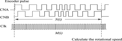
Figure 1. Velocity measurement principle of M/T method.
Figure 1 illustrates the speed measurement principle of the M/T method. Among them, CNA and CNB represent the two output signals of the encoder, usually used to determine the direction and position of rotation. Clk is a high-frequency clock signal used to provide an accurate time reference. N (i) is the number of feedback pulses collected during the sampling period, while M (i) is the number of clock pulses collected between two feedback pulse intervals. The M/T algorithm requires sensors to measure speed. The sensor used in this study is a photoelectric encoder. The M/T algorithm requires the sensor to measure the speed. The sensor used in the study is a photoelectric encoder. For the velocity measurement algorithm based on the photoelectric encoder pulse and time, the measurement principle is to use the timer to calculate the number of clock pulses between the two feedback pulses, and its reciprocal reflects the measured value of the rotational speed. The M method uses the counter to calculate the number of feedback pulses generated by the target rotation to express the speed of the target, but it is easy to produce the error of about two feedback pulses, so it is more applicable when measuring the high speed. The T method is to calculate the number of clock pulses between two feedback pulses, whose reciprocal reflects the measured value of the rotation speed. This method is suitable for low speed measurement, but it is easy to produce the error of a clock pulse unit when measuring the speed. For the velocity measurement algorithm based on the pulse and time of photoelectric encoder, the refresh rate of algorithm velocity is approximately equal to the algorithm period
Where
In the velocity measurement algorithm, the velocity resolution
In this study, the dynamic error is defined as the maximum difference between the measured velocity at a certain time and the actual velocity of the system, which is recorded as
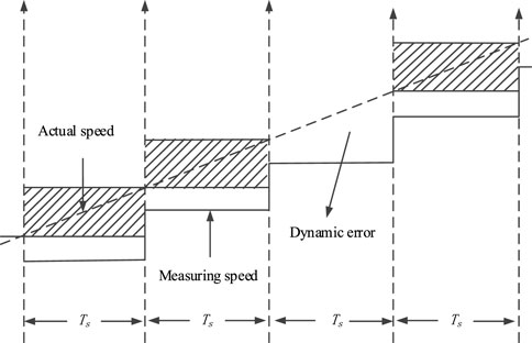
Figure 2. Dynamic error.
For the traditional M/T velocity measurement algorithm, its speed refresh rate is approximately equal to the sampling period
Where
The basic working characteristic of hydraulic mechanical transmission is that each stroke of the hydraulic motor continuously variable speed is matched with the appropriate transmission ratio of the reduction of the mechanical shunt stroke, and the continuously increased stepless speed change of the extended range is obtained by the confluence output of the two kinds of planetary banks of positive stroke and reverse stroke (Buhs and Wiens, 2018).
As a mature commercial software, ROMAX models the gear transmission system of ROMAX. Firstly, a digital model of the gear transmission system in Romax is created. This includes defining the geometric parameters of gears (such as number of pressure angle, etc.), material properties, meshing conditions, and shaft configuration. Next, the elastic coupling module is introduced. This module represents the flexibility of the gear transmission system, which can absorb and transmit torque fluctuations. Simultaneously, it can specify the performance parameters of the hydraulic pump. Finally, it will set up speed sensors and other measurement points in the model. The gear model is shown in Figure 3.

Figure 3. Analysis model of meshing gear based on Romax.
In the process of excavator rotation, the planetary gear rotates around its own central axis, and revolves around the rotation center planet through meshing with the inner ring gear. The planetary gear and the inner gear ring mesh with each other to generate vibration. In the dynamic analysis, the elastic sentinel deformation of planetary gear is mainly considered (Sun et al., 2019). In the process of vibration analysis of rotary transmission mechanism, it is assumed that only the radial force of the gear is considered and the axial force of the gear is ignored in the process of mutual sentinel contact between the planetary gear and the inner ring gear, and the elastic deformation between the rotary table and the rotary planetary gear shaft is not considered. The planetary gear drives the whole turntable and the working device to rotate together when the planetary gear revolves around the rotary central axis. This paper studies the vibration problem of the rotary transmission mechanism in the rotary process. Therefore, in the process of rotation, the moment of inertia of the working device and the rotary table is equivalent attached to the planetary gear (Figure 4).
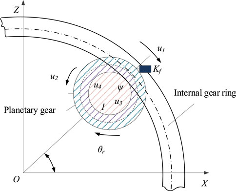
Figure 4. Mechanical model of rotary transmission mechanism.
In the rotary transmission mechanism of excavators, the planetary gear system is the core component, which allows the turntable and working device to rotate relative to the chassis. The picture shows the mechanical model of the rotary transmission mechanism, which includes planetary gears, internal gear rings, and the center of rotation O. In the figure,
According to the kinetic energy theorem, the kinetic energy of the rotary transmission system of excavator is expressed as Equation 5:
Where,
The planetary gear drive of the rotary transmission mechanism of the excavator is driven at a low speed. Therefore, the elastic displacement of the elastomer is relatively small. During the rotation of the excavator, the items of elastic motion and rigid body motion are ignored (Yan et al., 2019). The velocity relation of planetary gear can be expressed as Equations 6, 7:
Where
According to the principle of Lagrange equation, the dynamic equation of the rotary transmission mechanism of excavator can be expressed as Equation 8:
Where
Where
In the equation,
Pressure, velocity (angular velocity) and displacement (angular displacement) are used to evaluate the dynamic characteristics of hydraulic system. They can be determined by some basic equations.
(1) Pressure equation is as Equation 11.
Where
(2) Velocity and displacement equation is as Equations 12, 13.
Where
The above equation is the basic equation for establishing dynamic model of hydraulic system. The dynamic response of hydraulic system can be described by a set of first order linear and nonlinear ordinary differential equations according to the above equation.
The engine transfers the power to the hydraulic torque converter and finally to the wheels. The economy and power of the transmission system often depend on the performance of the engine. The test data of engine static characteristics can be obtained by bench test. These data can be used as the basis of theoretical analysis and modeling. The mathematical model is established by comparing and analyzing the actual test data. The external characteristic model ofthe engine is as Equation 14.
Where
Due to the complexity of the transmission error signal, it is difficult to analyze the transmission error signal comprehensively by single time-domain analysis or frequency-domain analysis. Therefore, this study uses the combination of time-domain analysis and frequency-domain analysis. The analysis method is as follows.
(1) The transmission error signal is filtered, amplified and statistically calculated to obtain the characteristic parameters of meshing gear in time domain.
(2) The time domain signal of transmission error is transformed into frequency domain signal, and the spectrum is analyzed. The gear transmission accuracy is analyzed by viewing the amplitude of meshing frequency and its related order, which also lays the foundation for gear fault diagnosis.
Figure 5 is the schematic diagram of transmission error measurement. The time domain signal of transmission error is obtained by comparing the angle parameters of two gears. Through DFT analysis, the frequency domain signal of transmission error is obtained. The common calculation equation of transmission error is as Equations 15, 16:
In the equation,
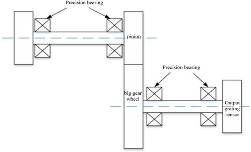
Figure 5. Schematic diagram of gear transmission error measurement.
To make the signal in phase, it is necessary to design a complex circuit to realize frequency division and frequency doubling. To improve the shortcomings of phase comparison method, digital counting measurement method can be used. The digital counting measurement method is to convert the transmission error into the corresponding pulse comparison. The output signals per revolution of input and output shaft sensors are set as
Based on the modeling and analysis of the gear transmission system in Romax, the transmission model between the engine output end and the hydraulic pump can be further constructed. This model can be regarded as an elastic coupling system, which converts the torque fluctuation of the engine into the pressure fluctuation of the hydraulic pump. The elastic coupling module mainly simulates the elastic coupling cooperation of the gear transmission system, and converts the torque fluctuation of the engine into the pressure fluctuation of the hydraulic pump. The speed sensor is mounted on the engine output shaft and is used to monitor the engine speed and speed. By measuring the speed and speed of the engine, the speed and acceleration of the transmission system can be calculated, thus assessing the size of the transmission error.
The main engine used in this test is Xugong xe230 III, the hydraulic system is Kawasaki negative flow system, and the power system is electric injection engine. Engine Cummins QSB 6.7 EFI diesel engine is with rated power/rated speed of 142k W/2,200 rpm. The working medium of this test is No. 8 hydraulic transmission oil with a density of 860 kg/m³. In this test, the transmission model of the hydraulic transmission system includes the following components. Hydraulic pump (Kawasaki negative flow pump) converts mechanical energy into hydraulic energy and provides hydraulic fluid to other components of the hydraulic system. Kawasaki negative flow pump is a common type of hydraulic pump, and its working principle is based on the centrifugal or axial plunger design. The v,e are proportional valve and directional control valve. Tubing and piping, which are used to connect hydraulic components for transmitting hydraulic fluid. Hydraulic cylinder block converts hydraulic energy into mechanical energy, generating linear or rotational motion. The temperature range of the bench test shall be between 50 and 80°C (Figure 6).
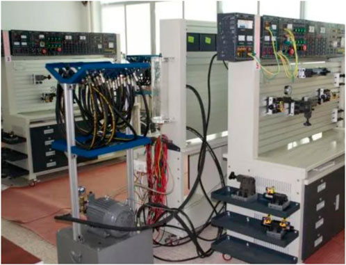
Figure 6. Hydraulic transmission test bench.
The test bench consists of an electric motor, a torque and speed sensor, eddy current measurement and control equipment, and a collection and control section. Firstly, the motor converts energy into mechanical work by transmitting power, thereby driving the entire hydraulic transmission system. Secondly, the torque and speed sensor is used to measure the torque and speed on the motor output shaft. It can provide critical feedback information, including mechanical power and efficiency. Eddy current measurement and control equipment is used to measure the velocity and flow rate of liquid in hydraulic systems. This can help determine the flow characteristics of the hydraulic system. Finally, the collection and control section is responsible for receiving and processing the data obtained from the sensors and the measuring equipment, receiving the data at a frequency of 50 times per second. The system composition is shown in Figure 7.
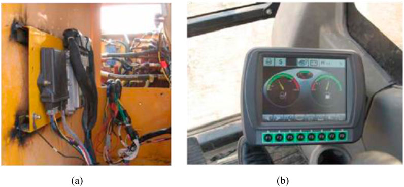
Figure 7. Installation of main controller and multifunction monitor. (A) Main controller; (B) Multifunction monitor.
Three phase asynchronous motor with frequency conversion and speed regulation is selected as the driving device. The parameters of the motor used in the test are shown in Table 1.

Table 1. Technical parameters of motor.
In the transmission error test, because the data sampling frequency is 100 MHz, when the speed is too high, it will result in signal distortion. Therefore, the transmission error test is conducted at low speed conditions, using the incremental grating sensor with the sensor model Kistler 4045A, which is connected to the digital input channel of the data acquisition system through the output interface (such as EnDat). A pressure sensor is utilized to measure the outlet pressure of the pump. The pressure sensor is installed at the pump outlet position in the hydraulic system to accurately measure hydraulic pressure. The measurement method can include the following steps. Firstly, a pressure sensor is installed on the outlet pipeline of the pump with a strain gauge pressure sensor. This type of sensor utilizes the principle of a strain gauge to measure pressure. It contains an elastic element (usually metal) that undergoes small deformation when subjected to pressure, resulting in changes in physical quantities such as resistance, capacitance, or inductance. Then the sensor is connected to the data acquisition system. The pressure sensor is needed to be calibrated before the experiment to ensure accurate pressure measurement. The data of the pump outlet pressure over time should be recorded during the engine start under the fault condition of the hydraulic press. The experimental results are shown in Figure 8.
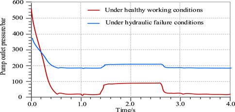
Figure 8. Variation curve of pump outlet pressure.
From Figure 8, the pump outlet pressure fluctuates between the interval [200,400]. Then the pump is severely affected when the engine starts to start. At this time, the pump outlet pressure increases rapidly and reaches the peak value instantly. After 0.4 s fluctuation, it reaches a stable state. At this time, the pump outlet pressure maintains at a stable value. When the first second, the valve core of the main control valve starts to move, and the outlet pressure of the pump fluctuates accordingly. During the period of 1–1.5 s, the outlet pressure of the pump also increases continuously. After 1.6 s, the excavator run at a constant speed. At 2.5 s, as the valve core of the main control valve begins to close, the excavator gradually decelerates, and the outlet pressure of the pump also decreases. When at the third second, the main control valve is completely closed, and the pump outlet pressure oscillates. After 0.2 s, the pump outlet pressure is equal to the overflow pressure (Figure 9).
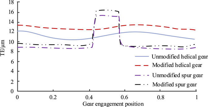
Figure 9. Transmission error of spur and helical gears.
With the increase of modification, the deformation of gear teeth is gradually increased, but the change of gear stiffness tends to be gentle. At this time, although the tooth deformation is large, the transmission system is stable, and there is no obvious impact of meshing in and meshing out. From this point of view, the large modification is conducive to reducing the transmission error, but on the other hand, the gear tooth deformation is large, indicating that the gear unit tooth the gear is easy to cause fatigue damage due to its large load. Therefore, the influence on the tooth deformation and service life should be considered comprehensively when selecting the gear profile modification. The experimental results of monitoring the transmission error of hydraulic excavating machinery using the M/T algorithm proposed in the study are shown in Figure 10.
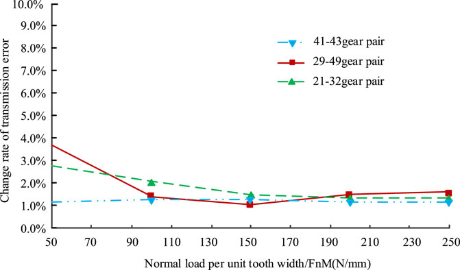
Figure 10. Change rate of transmission error ratio of different gear pairs.
From the above figure, the change rate of transmission error is less than 5%, and the change rate of transmission error is less than 2% when the normal load of unit tooth width FnM > 100N/mm.
This study proposed a transmission error monitoring method for hydraulic excavating machinery based on the M/T algorithm. The experimental results showed that under normal load of unit tooth width F, the change rate of transmission error was less than 5%, and the change rate of transmission error was less than 2% nM > 100N/mm. Under hydraulic failure conditions, the pump outlet pressure fluctuated between the range of [20,400]. When the hydraulic system was in a healthy working state, the pump was severely affected when the engine starts. At this point, the outlet pressure of the pump rapidly increased and immediately reached its peak. At this point, the outlet pressure of the pump remained at a stable value. During the period of 1–1.5 s, the outlet pressure of the pump also increased continuously, and after 1.6 s, the excavator ran at a constant speed. At 2.5 s, as the valve core of the main control valve began to close, the excavator gradually slowed down, and the outlet pressure of the pump also gradually decreased. As the modification amount increased, the deformation of gear teeth gradually increased, but the change in gear stiffness tended to be gradual. At this point, although the tooth shape deformation was significant, the transmission system was relatively stable and the impact of meshing in and out was not significant. In summary, the mechanical transmission error monitoring method proposed in the study has good stability and accuracy. However, relevant research has not yet been widely applied to various types of mechanical error detection, which is also an area that needs to be followed up in subsequent research.
The original contributions presented in the study are included in the article/supplementary material, further inquiries can be directed to the corresponding author.
FC: Data curation, Formal Analysis, Funding acquisition, Writing–original draft, Writing–review and editing.
The author(s) declare that financial support was received for the research, authorship, and/or publication of this article. This study is supported by Research on Key Technologies for Controlling the Effect of Weakening Residual Magnetism in the Magnetic Field of Magnetic Levitation Bearings (NO. 232102220091).
The author declares that the research was conducted in the absence of any commercial or financial relationships that could be construed as a potential conflict of interest.
All claims expressed in this article are solely those of the authors and do not necessarily represent those of their affiliated organizations, or those of the publisher, the editors and the reviewers. Any product that may be evaluated in this article, or claim that may be made by its manufacturer, is not guaranteed or endorsed by the publisher.
Barmaki, R., and Ehghaghi, M. B. (2019). Experimental investigation of a centrifugal pump hydraulic performance in hydraulic transmission of solids. Mech. Mech. Eng. 23 (1), 259–270. doi:10.2478/mme-2019-0035
Buhs, J. W. V. D., and Wiens, T. K. (2018). Modeling dynamic response of hydraulic fluid within tapered transmission lines. J. Dyn. Syst. Meas. Control 140 (12), 121008. doi:10.1115/1.4040667
Geoffrey, R. (2019). Transmission point spread function of a turbid slab. J. Opt. Soc. Am. A, Opt. Image Sci. Vis. 36 (10), 1617–1623. doi:10.1364/josaa.36.001617
Han, L., He, X., Ning, Y., Zhang, Y., and Zhou, Y. (2023). Fatigue damage diagnosis and prognosis for 2024 aluminum plates with center holes: a strain monitoring approach. Int. J. Fatigue 170, 107535–107539. doi:10.1016/j.ijfatigue.2023.107535
He, X., Xiao, G., Hu, B., Tan, L., Tang, H., He, S., et al. (2020). The applications of energy regeneration and conversion technologies based on hydraulic transmission systems: a review. Energy Convers. Manag. 205, 112413. doi:10.1016/j.enconman.2019.112413
Kan, Y., Sun, D., Luo, Y., Qin, D., Shi, J., and Ma, K. (2019). Optimal design of the gear ratio of a power reflux hydraulic transmission system based on data mining. Mech. Mach. Theory 142, 103600. doi:10.1016/j.mechmachtheory.2019.103600
Lin, Y., Wu, Z., Zhang, H., Li, Y., Guo, H., and Zheng, Y. (2022). Research on the unsteady characteristics of francis turbines under the low load operation. China Rural Water Hydropowe 12, 180–187. doi:10.12396/znsd.220289
Mikolajewicz, N., Sehayek, S., Wiseman, P. W., and Komarova, S. V. (2019). Transmission of mechanical information by purinergic signaling. Biophysical J. 116 (10), 2009–2022. doi:10.1016/j.bpj.2019.04.012
Ni, X., and Bao, M. (2020). Dynamic test of hydro mechanical composite transmission for cotton picker. J. Beijing Inst. Technol. (3), 366–378. doi:10.15918/j.jbit1004-0579.20042
Park, J., Seo, C., Boo, K., Kim, H., Detand, J., and Ruxu, D. (2018). Geometry modification of helical gear for reduction of static transmission error. MATEC Web Conf. 167 (9), 02013. doi:10.1051/matecconf/201816702013
Rezazadeh, N., Felaco, A., Fallahy, S., and Lamanna, G. (2023). Application of supervised and unsupervised machine learning to the classification of damaged rotor-bearing systems. Macromol. Symp. 411, 2200219. doi:10.1002/masy.202200219
Sun, X., Han, L., and Wang, J. (2019). Design and transmission error analysis of CBR reducer. J. Mech. Des. 141 (8), 1. doi:10.1115/1.4043368
Tan, X., Chen, W., Zou, T., Yang, J., and Du, B. (2023). Real-time prediction of mechanical behaviors of underwater shield tunnel structure using machine learning method based on structural health monitoring data. J. Rock Mech. Geotechnical Eng. 15 (4), 886–895. doi:10.1016/j.jrmge.2022.06.015
Valentín, D., Presas, A., Egusquiza, M., Valero, C., and Egusquiza, E. (2018). Transmission of high frequency vibrations in rotating systems. Application to cavitation detection in hydraulic turbines. Appl. Ences 8 (3), 451. doi:10.3390/app8030451
Xu, X., Sun, W., Cai, T., Liu, Y., and Han, X. (2018). Design of a hydraulic control unit for a two-speed dedicated electric vehicle transmission. Automot. Innov. 1 (4), 300–310. doi:10.1007/s42154-018-0039-3
Keywords: M/T algorithm, hydraulic, excavating machinery, transmission error, monitoring
Citation: Chen F (2025) Transmission error monitoring method of hydraulic excavating machinery based on M/T algorithm. Front. Mech. Eng. 11:1425211. doi: 10.3389/fmech.2025.1425211
Received: 29 April 2024; Accepted: 20 January 2025;
Published: 17 February 2025.
Edited by:
Mohamed Arezki Mellal, University of Boumerdés, AlgeriaReviewed by:
Shuvodeep De, Texas State University, United StatesCopyright © 2025 Chen. This is an open-access article distributed under the terms of the Creative Commons Attribution License (CC BY). The use, distribution or reproduction in other forums is permitted, provided the original author(s) and the copyright owner(s) are credited and that the original publication in this journal is cited, in accordance with accepted academic practice. No use, distribution or reproduction is permitted which does not comply with these terms.
*Correspondence: Fang Chen, ZWNob19jZmxmeUAxNjMuY29t
Disclaimer: All claims expressed in this article are solely those of the authors and do not necessarily represent those of their affiliated organizations, or those of the publisher, the editors and the reviewers. Any product that may be evaluated in this article or claim that may be made by its manufacturer is not guaranteed or endorsed by the publisher.
Research integrity at Frontiers
Learn more about the work of our research integrity team to safeguard the quality of each article we publish.