 Mayuka Kojima
 Shunsuke Yoshimoto
 Akio Yamamoto
- 1Department of Human and Engineered Environmental Studies, Graduate School of Frontier Sciences, The University of Tokyo, Kashiwanoha, Japan
- 2Department of Mechanical Engineering, Graduate School of Engineering, Osaka University, Suita, Japan
This paper discusses the design of a two-degree-of-freedom (2-DOF) pseudo-force presentation device for a palm. The device was designed to present pressure stimulation to a palm to invoke a pseudo-force sensation. In addition, the stimulator can rotate to invoke a pseudo-torque sensation through tangential skin stretch in the proximal/distal direction. Whereas the previous devices used for pseudo-force presentation on a palm utilized voice coil motors (VCM) to generate pressure, the developed device uses a DC gear motor, cam, and lever, which comprise a series elastic actuator (SEA). Although the mechanism’s response is slower than the VCM-based device’s, it can realize lower power consumption when generating constant force. The paper discusses the design requirement to provide sufficient pseudo-force sensation. Then, a prototype device was evaluated, which satisfied the requirements regarding size, weight, force, and stroke. The device was utilized in a human-subject experiment to investigate the effect of tangential skin stretch along the proximal/distal direction on a palm. The results showed that the stimulation can invoke the feeling of rotation, or pseudo-torque sensation.
1 Introduction
Metaverse, a multi-user environment that merges physical reality and digital virtuality, is attracting attention and increasing demand for immersive virtual reality (VR) (Mystakidis, 2022). In VR, the presentation of force perception enhances the sense of presence and intuition and improves the efficiency of operation (Stone, 2001; Hayward et al., 2004). Combining force perception with visual and auditory perception using a head-mounted display (HMD) for immersive VR is particularly effective (Ramsamy et al., 2006; Cooper et al., 2018; Martin et al., 2022). Applications combining force presentation and VR have been investigated in various fields, such as teleoperation (Artigas et al., 2016; Moya et al., 2021; Gong et al., 2022), virtual training (Gibo et al., 2014; Escobar-Castillejos et al., 2016), remote simulated surgery (Abdi et al., 2020; Rassi and Rassi, 2020; Patel et al., 2022), and entertainment (Lopes et al., 2018; Shim et al., 2020; Wei et al., 2020).
However, force feedback devices are generally large and must be grounded (fixed to a rigid support such as a tabletop), which restricts their portability and operability (Silva et al., 2009; Arata et al., 2011). Pseudo-force presentation has attracted attention as a means to solve this problem. Pseudo-force presentation is a method to create an illusion of force by using non-force stimuli, such as visual or tactile stimuli (Collins and Kapralos, 2019; Ujitoko and Ban, 2021). If appropriately designed, vision or tactile sensation can invoke force sensation, even though physical force does not exist. Here, “tactile sensation” refers to those perceived on the surface of a skin, whereas “force sensation” refers to perception from muscles and tendons. When people touch an object, they simultaneously obtain and integrate visual, tactile, and force information to perceive its properties (Culham and Valyear, 2006; Whitaker et al., 2008). Even if the force information is not provided, simultaneously presenting visual and/or tactile information can invoke force sensation, which is the pseudo-force sensation. Generally, a device presenting a pseudo-force sensation is easier to control than a force display that exerts real force. Also, while force displays need to be grounded, pseudo-force devices do not require grounding, which makes them portable.
Previous studies on pseudo-force perception primarily focused on visual stimuli (Ujitoko and Ban, 2021). However, the amount of force sensation invoked by visual stimuli is limited. To obtain a larger pseudo-force effect, tactile stimuli have attracted attentions (Amemiya et al., 2008; Hachisu et al., 2011; Schorr and Okamura, 2017). Most of the studies using tactile stimuli have targeted the fingertip, where mechano-receptors are known to distribute densely. In those studies, researchers have studied tangential stimulation, known as “skin stretch,” and pressure stimulation in the normal direction (Prattichizzo et al., 2010; Schorr and Okamura, 2017).
In VR and teleoperation systems, grip-type controllers are commonly used. In those controllers, a palm is always in contact with the controller, and thus, a palm seems the most suitable target area for skin stimulation, rather than a fingertip. Even in daily life, people often grasp and manipulate objects using their palms, highlighting the importance of a palm as the target area for skin stimulation. Nevertheless, while many studies of pseudo-force have been conducted on fingertips, studies on palms remain limited.
The skin of a palm can be stimulated in three directions: two tangential directions, which are radial/ulnar direction and proximal/distal direction, and the direction normal to the skin surface, as shown in Figure 1. Several studies have been conducted to prove that pseudo-force sensation can be invoked by normal pressure (Asada et al., 2016; Nakamura et al., 2018; Sakaniwa et al., 2021; Yoshimoto and Yamamoto, 2021; Kojima et al., 2022; 2023). Asada et al. (2016) developed a grip-type device that can provide normal pressure stimulation to a palm and compared the induced pseudo-force sensation with physical force applied to the grip. Yoshimoto and Yamamoto (2021) proved that pseudo-force can be perceived even when the pressure stimulus is presented passively. Kojima et al. (2022) confirmed that a narrower stimulator is more effective and causes fewer individual differences in pseudo-force perception. For tangential stimulation, previous studies have shown that stimulation along the radial/ulnar direction can invoke torque sensation (Guinan et al., 2014; Guzererler et al., 2016). However, research on tangential stimulation along the proximal/distal direction is lacking.
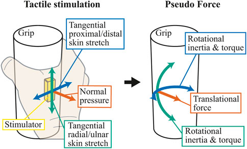
Figure 1. Three different tactile stimuli that can be presented to the palm and the pseudo force/torque perception induced by each stimulus. Green arrows indicate tangential radial/ulnar skin stretch stimulus, blue arrows indicate tangential proximal/distal skin stretch stimulus, and red arrows indicate normal pressure stimulus. Tangential skin stretch stimuli would invoke the feeling of torque, while normal pressure stimuli provide the feeling of translational force.
In the previous studies on palm stimulation, presentation devices provided stimulation in only one direction. Combinations of tangential and normal stimuli would extend the application scenarios of the pseudo-force devices. The development of such devices is also useful for studying the properties of pseudo-force perception, which are still not fully understood. With those in mind, this paper aims to design a pseudo-force presentation device with a stimulator’s two-degree-of-freedom (2-DOF) motions. Considering the lack of and need for studies on proximal/distal tangential stimulation, a combination of the normal and proximal/distal directions is chosen.
The device in the previous studies used voice coil motors (VCM) (Asada et al., 2016; Nakamura et al., 2018) to provide pressure stimulation in the normal direction. VCMs allow easy force control since their output force is directly proportional to the coil current. However, since VCMs are used without reduction gears, large VCMs need to be employed to provide stronger stimulations, resulting in a large and heavy device structure. Also, as VCM is highly back-drivable, it needs to keep a constant current flow during the presentation of constant stimulation, which results in larger power consumption and overheating of the device. These can be fatal problems in developing the 2-DOF device since realizing 2-DOF motions would require a much more complicated structure.
To overcome the problems, this work employs a series elastic actuator (SEA) (Pratt and Williamson, 1995) as an alternative to VCM. To avoid enlarging the grip’s size, force on the stimulator will be transmitted using a cam and a lever from a DC gear motor located in a remote place in the device. A spring will be connected to the tip of the lever to allow force control. Then, the whole mechanism will be rotated by another motor to realize 2-DOF motions. This paper describes the design details and shows the effectiveness of tangential stimulation along the proximal/distal direction.
The remainder of the paper is organized as follows. The next section will present the device’s concept and discuss its requirements. In Section 3, mechanical elements, such as motor, cam, and lever, will be designed or selected to satisfy the requirements. The prototype device will be presented in Section 4, and its performance will be experimentally verified. The device’s performance will be compared to that of the previous device using a VCM. The device will also be utilized in a human subject experiment, in which the effectiveness of the tangential stimulation along the proximal/distal direction will be investigated. The results will show that the tangential stimulation can invoke a pseudo-torque feeling. Finally, Section 5 provides the conclusions.
2 Concept and requirements for the device
This study aims to develop a device that enables pseudo-force/torque presentation in two directions while the user holds the device. This section first presents the overall concept and discusses the requirements.
2.1 The target stimulation area and the overall device structure
Figure 2 shows the target area of the stimulation of this work. Kojima et al. (2023) demonstrated that a normal pressure stimulus produces a pseudo-force sensation over a broad area of the hand, extending from the base of the thumb to the fingertips. Therefore, the same area is targeted in this work.
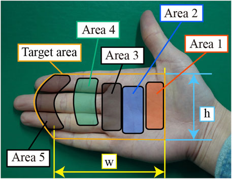
Figure 2. The target stimulation area on the palm, indicated by the orange line. Although the left edge of the orange region is curved, it will become almost straight when the palm grips a cylinder, resulting in a rectangular region. Areas one through five indicate the areas used in the experiments.
To stimulate the above target area, this work proposes a device structure shown in Figure 3A. The device’s external shape is a stepped cylinder, and a user is supposed to grip the smaller diameter part shown in Figure 3B. The smaller part, referred to as the “gripping part”, is equipped with a stimulator to pressurize the palm in contact. The larger diameter part contains motors that rotate and extrude the stimulator. For extrusion, the device utilizes the SEA mechanism. A DC gear motor actuates a lever using a cam connected to its axis, and the force is transmitted to the other side of the lever. Springs are installed on the other end of the lever, and the springs push the stimulator. The springs behave as the elastic elements required for SEA. The deformation of the springs, which is proportional to the force output, is monitored using a photo-interrupter, which functions as a simple displacement sensor. The spring deformation is regulated by a feedback controller. Then, another motor (an RC servo motor) rotates this whole mechanism to realize tangential motions along the proximal/distal direction.
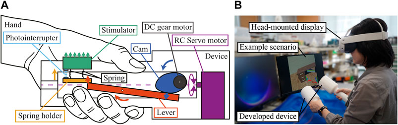
Figure 3. The concept of the 2-DOF device. (A) Basic structure. The stimulator, driven by series elastic actuator (SEA), pushes a palm to provide a pseudo-force sensation. The RC servo motor can rotate the SEA module for tangential stimulation. (B) Expected usage scene: experiencing VR with pseudo-force feedback from the devices.
This structure has the following advantages compared to the previous device using VCMs. First, with this structure, we can avoid enlarging the grip size. The previous device arranged VCMs directly beneath the stimulator to allow direct force control. Such a structure, however, tends to enlarge the grip size, especially when a large force is required. On the other hand, the proposed structure can use a relatively smaller gear motor since the gear and the lever can leverage the force. Also, the motor can be placed apart from the stimulator, which allows us to keep a moderate grip size.
The second advantage is lower power consumption in a continuous presentation. A VCM needs to keep a constant current when outputting a constant force to the simulator, as the output force is directly determined by the current. This can cause an overheating problem in a continuous presentation. In the proposed structure, on the other hand, the reduction gear’s poor back-drivability, or self-locking, can be utilized to maintain a constant output force without feeding much current to the gear motor. In addition, even if the motor is heated, it will hardly affect the palm stimulation due to the distance between the simulator and the motor.
In the remainder of this section, several requirements for designing this device are discussed.
2.2 Size of the gripping part
This work assumes a cylindrical grip, considering that many everyday objects we grip have cylindrical or similar shapes. As this work aims to stimulate the areas shown in Figure 2, the contact area between a hand and the cylinder must be larger than the target area.
First, the length of the cylinder of the gripping part must be larger than the length “
The requirement for the cylinder’s circumference can be derived from the length of the simulation area (which is “
In addition, the comfort of gripping should also be considered when determining the circumference; if the circumference, or the diameter, is too large or too small, the user might feel difficulty in gripping the cylinder. According to Hall and Bennett (1956); Yakou et al. (1997); Kong and Lowe (2005), cylinders are most comfortably grasped when the diameter is between 30 mm and 50 mm. If the diameter falls within this range, the resulting circumference is between 94 mm and 157 mm. From the above two factors, the circumference should be between 146 mm and 157 mm or between 46 mm and 50 mm in terms of diameter.
2.3 Normal stimulation force
In the previous studies (Asada et al., 2016; Yoshimoto and Yamamoto, 2021; Kojima et al., 2022), pressures of up to approximately 8.9 kPa were applied to the palm to generate a sufficient amount of pseudo force sensation. The experimental results of the studies showed that the pseudo-force effect was not saturated at the pressure, suggesting that a much larger pressure could be used. With that in mind, this study aims at providing 20 kPa. If we assume that the pressure is uniform on the surface of the stimulator, the required normal force can be calculated from the surface area. If, for example, the surface area is 500 mm2, which is the case for this work, the maximum force of 10 N is required.
2.4 Stroke for normal stimulation
When normal force is applied to a palm, the surface of the palm is deformed by the force. The stimulator should follow the palm’s deformation to keep applying force, which determines the required stroke.
It has been reported that the relation between the displacement and the applied force is not linear on fingertips, forearms, and feet (Hajian and Howe, 1997; Zheng and Mak, 1997; Zheng and Mak, 1999; Fujita, 2004). However, the relationship on a palm has not been extensively studied. Also, the relation could differ among regions on a palm. Therefore, we measured skin displacement on a palm at multiple points, for one of the authors. An indentor, of which detail will be described in Section 3, was used.
In the experiment, forces ranging from 0 N to 10 N were applied at 1 N intervals to the three areas depicted in Figure 2, which are the ball of the thumb (area 1), the center of the palm (area 2), and the proximal phalanx of hand (area 4). For measuring area 1, the center of the stimulator was positioned at the crease at the base of the thumb; for area 2, the metacarpophalangeal joint (MCP joint) connecting the end of the distal palmar crease and the end of the proximal palmar crease; and for area 4, the center of the proximal interphalangeal crease of the index finger and the palmar digital crease.
The measurement setup is shown in Figure 4A, with the stimulator pressed against a fixed hand in the grip grasping posture. The indentor was connected to a force gauge (RX–10, Aiko Engineering Co., Ltd.) for force measurement that was arranged on a micrometer-driven linear positioning stage. Indentation was carried out by moving the force sensor. The measurement was repeated three times in each area.
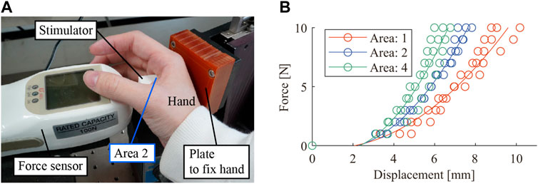
Figure 4. Measurements of skin deformations. (A) Measurement setup of skin deformation during force application to the palm using a stimulator. The hand was in the device’s grasping posture and was fixed on the fixation plate, and the stimulator was pressed against the hand. (B) The skin displacements in Areas 1, 2, and 4. The deformation at 10 N, measured using the fitting curves, were 9.6, 7.6 and 6.7 mm, respectively.
The results are shown in Figure 4B. Since some previous studies approximate the relation on a fingertip using quadratic functions (Hajian and Howe, 1997; Fujita, 2004), we also employed quadratic functions for approximating the measured data, as shown in Figure 4B. The quadratic approximation curves reach 9.6, 7.6 and 6.7 mm, respectively for the three areas, at force of 10 N. These results indicate that the stimulator must stroke about 10 mm to guarantee an applied force of 10 N on the softest area (area 1).
2.5 Response time of output force
In SEA, the response speed of output force is relatively slow since SEA needs to compress the elastic element to generate output force. The slow response might cause discomfort in virtual reality applications; to avoid discomfort, it is important to synchronize the force output with the visual information. According to Miyasato and Nakatsu (1997), allowable delay between visual and tactile presentations is approximately 120 m. This means that, ideally, the device should be able to change the output force from 0 to 10 N within this time period. This, however, is not a strict requirement since, in typical contact, the contact force grows with time. The above condition must be satisfied only when a sudden collision needs to be rendered, which is not the case for this device. Nevertheless, the above numbers can serve as a design reference for response time.
2.6 Rotation speed and torque
In the proposed device structure, an RC-servo motor rotates the whole mechanism for tangential stimulation along the proximal/distal direction. The motor should have enough rotational speed to provide skin stretch, and the speed used for radial/ulnar tangential stimulation can serve as a reference. In Guzererler et al. (2016) that studied radial/ulnar skin stretch, the speed was 64 mm/s. By adopting the speed as a reference, the rotational speed required for the motor is derived as 2.6 rad/s based on the diameter of the device (50 mm).
Subsequently, the torque required to present skin stretch stimuli is considered. The force along the tangential direction can be determined from friction. Although estimating the friction coefficient is difficult for a palm due to its non-flat structure, we assume it is 1. With the friction coefficient of 1, the maximum tangential force becomes 10 N. If the device diameter is 46 mm, the moment arm for tangential stimulation will reach 33 mm when the stimulator extrudes 10 mm from the device surface. This implies that the torque required in the rotational direction is 0.33 N m.
2.7 Device weight
One motivation for introducing the SEA mechanism was to avoid the heavy device weight caused by large VCMs. If the device is too heavy, it will affect the results of experiments when it is employed in a psycho-physical experiment to investigate the pseudo-force effect. Also, in virtual reality applications, a device that is too heavy will make the user uncomfortable.
In a previous study (Research Institute of Human Engineering for Quality Life, 2000), the maximum weight that could be easily carried was determined using cylinders of various weights on subjects aged 20 to 89. The study suggests that a weight less than 1 kg is easily carried with one hand. Therefore, the target weight of the device should be 1 kg or less.
3 Design details
As already stated, this work utilizes SEA to actuate the stimulator in the normal direction. This section mainly discusses the design of an SEA module to meet the requirements discussed above.
3.1 Elastic element of SEA
In SEA, the output force is proportional to the deformation of the elastic element, which in this study is the springs arranged at the tip of the lever. As examined above, since the palm surface deforms when it is indented, the base of the springs (spring holder) must be able to move for the length of the springs’ deformation plus the palm’s deformation. Therefore, we employed a compact linear guide (BSGM6–25, MISUMI Corporation) with a stroke of 14 mm to support the spring holder (see Figure 3A). Four springs (WM3–10, MISUMI Corporation), with a spring constant of 2 N/mm, a rated maximum deflection of 3.5 mm, and a natural length of 10 mm, were arranged in parallel on the spring holder. Then, the other end of the springs was connected to the stimulator.
The rated maximum load of the springs was 6.9 N, and the four springs can withstand 27.6 N, which is larger than the output force requirement of 10 N. When 10 N is applied to the four springs, the springs contract by 1.25 mm, which falls within the stroke of the linear guide when the maximum indentation stroke of 10 mm is added. The spring deformation, which is equivalent to the output force, was measured using a photo-interrupter (SG–105, KODENSHI Corporation).
3.2 DC gear motor
The rated output of the motor must exceed the required output against the palm. As discussed in Section 2, the stimulator must move a distance of 10 mm with a maximum output force of 10 N, preferably within 0.12 s, This means that the motor’s peak output of 0.83 W is preferred. This work adopted a DC gear motor (2619S024SR 112:1, IE2–16, FAULHABER), which has the maximum intermittent torque of 180 mN m, and the no-load speed of 6.8 rad/s.
3.3 Cam and lever
The cam and the lever were designed from the reference values of the output force and speed. The required force at the stimulator is 10 N while the maximum speed preferably exceeds 94 mm/s, which is derived from the motion stroke (10 mm for palm deformation and 1.25 mm for spring deformation) and the response time (0.12 s). In the device, the cam converts the motor’s rotational motion into translation, which the lever then transmits to the stimulator. Figure 5 illustrates the relationship between the cam, lever, and spring holder. This lever works as a flat-face follower, and the cam is designed to have a linear relation between the rotation angle and the lift.
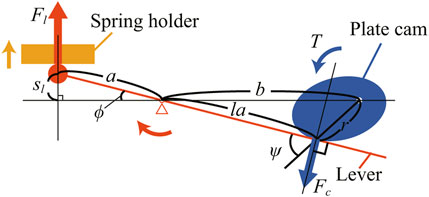
Figure 5. Geometric model showing the relationship between the cam, lever, and the spring holder.
3.4 Torque-force relation
Regarding forces on both ends of the lever, Eqs 1, 2 hold.
where
For simplicity, we assume that cam’s rotation angle
where
Then,
In the actual device, the contact point between the cam and lever shifts as the cam rotates, which will change the length ratio of the lever. However, for simplicity, we assume this change is negligible. Then,
Since the right side of Eq. 7 decreases monotonically for positive
3.5 Displacement and speed
Ideally, the displacement of the spring holder,
From the geometrical relations,
Therefore, the initial and final angles of the cam should satisfy Eq. 10.
Also, from the response time of 0.12 s and the motor’s maximum speed of 6.8 rad/s, Eq. 11 is obtatined.
3.6 Final design
Assuming that the stimulator is located almost in the middle of the grip length, the lever’s length must be larger than half the length of the grip (45 mm) and the maximum cam lift
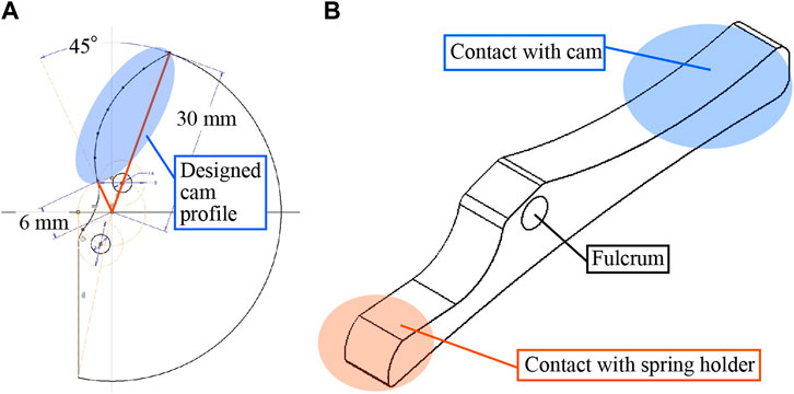
Figure 6. The Design of the cam and lever. (A) The designed cam profile spans over 45°, with the minimum lift of 6 mm and the maximum of 30 mm. (B) The designed lever. The length to the contact point from the fulcrum is 54 mm for the cam and 31 mm for the springs.
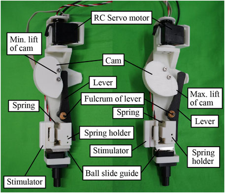
Figure 7. The developed SEA module to extrude the stimulator. The two photos show the same module in different cam angles, with the angles corresponding to the minimum and the maximum cam lift.
3.7 Whole device structure
The developed device is depicted in Figures 8, 9. The device was mainly made of polyacetal resin (POM) and polylactic acid resin (PLA). The total length and weight were 230 mm and 440 g, respectively, with the grip part (the smaller diameter cylinder) being 110 mm in length and 50 mm in diameter. The grip has a cavity to allow the stimulator to extrude, as shown in Figure 9. The size of the cavity was 78.5 mm in its arc length (180
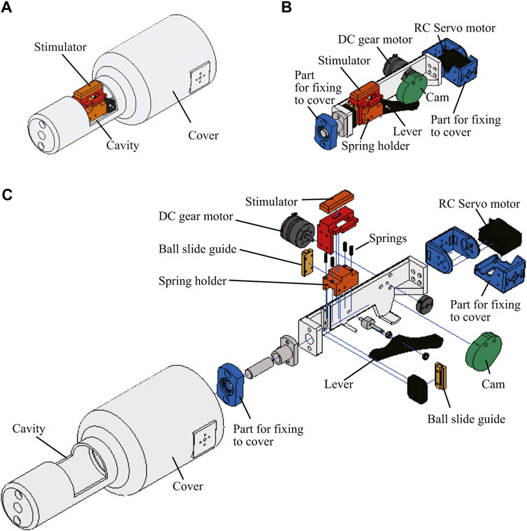
Figure 8. CAD drawing of the device. (A) The entire device. The user grasps the smaller diameter part of the stepped cylindrical shape. (B) CAD drawing of the SEA module. (C) Exploded view.
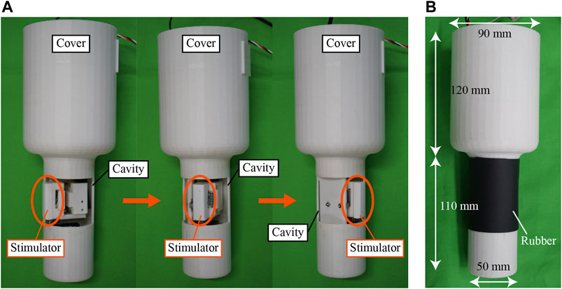
Figure 9. Appearances of the developed device. (A) The stimulator rotates inside the cavity and pops out. (B) The cavity can be covered with a soft rubber sheet, although it was not used in this work.
The SEA module was installed inside the shell of the stepped cylindrical shape. In the larger diameter part, an RC servo motor (KRS-3204R2 ICS, Kondo Kagaku Co., Ltd.), which has the maximum output torque of 0.91 N m and the maximum rotation speed of 8.1 rad/s, was installed to rotate the SEA module.
The SEA module was controlled by a microcontroller (Mbed NXP LPC1768, Arm Limited). The photo-interrupter in the SEA module detected the spring deformation, which corresponds to the output force. The reading of the photo-interrupter was fed to the controller, which was regulated to follow a reference signal using P (proportional) or PI (proportional and integral) control. The RC servo motor for rotation was controlled by a position command generated in another microcontroller (ESP32–DevKitC V4, Espressif Systems (Shanghai) Pte. Ltd.).
4 Evaluation of the device
4.1 Maximum force in the normal direction
Regarding the stimulator’s force along the normal direction, the maximum output force was measured throughout the stroke of the stimulator. The stimulator was arranged to contact with the force gauge, which was set on a linear stage, as shown in Figure 10A. The SEA module controller was given a saturating input, and the force gauge measured the output force from the stimulator. The measurements were done for the stimulator position from 0 mm to 14 mm with 1 mm intervals.
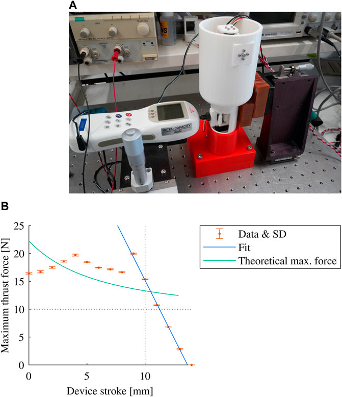
Figure 10. Measurement of the maximum stimulator force. (A) Measurement setup. (B) Measured results. The dashed horizontal line indicates the required force of 10 N.
Figure 10B shows the results of five measurements. Throughout the designed motion stroke from 0 mm to 10 mm, the maximum force exceeded 10 N, which is the requirement. The light green line represents the expected maximum force calculated using Eq. 7. The measured results followed a similar curve between 4 mm and 8 mm, although the measured force was larger than the expected one. This would be because the motor’s output torque was probably larger than the specifications. Nevertheless, their qualitative agreement validates the design process.
The discrepancy for the position smaller than 4 mm was found to have been caused by geometrical interference between the cam and the lever near the end of the stroke. Conversely, the maximum force linearly decreased for the position larger than 9 mm. This was because the spring holder reached the end of its stroke and could not compress the spring any further. In this region, the maximum force should decrease with a rate identical to the spring constant, which was 8 N/mm. However, the measured rate was 4.15 N/mm. This would be because the design around the simulator was not symmetric (the stimulator was held by the linear guide on one side) and thus some additional deformation occurred.
Although some discrepancies were found in the measurement, the maximum thrust force was found to exceed the required output force of 10 N in the designed range from 0 mm to 10 mm.
4.2 Steady-state response in the normal direction
The steady-state response regarding force control in the normal direction was measured at three different stimulator locations, which are 0, 5, and 10 mm from the surface of the device. The SEA module was controlled either in P or PI control, and the force gauge measured the steady-state outputs for different force command inputs. The results are shown in Figure 11. As some error was observed when the force command returned to zero, the output for 0 N input was measured by changing the input from 1 N to 0 N. The input was changed from 0 N to the intended value for the other inputs. The output was found to be almost linear to the input regardless of the control mode and the stimulator position. Although some steady-state errors were observed for P control, the error was within
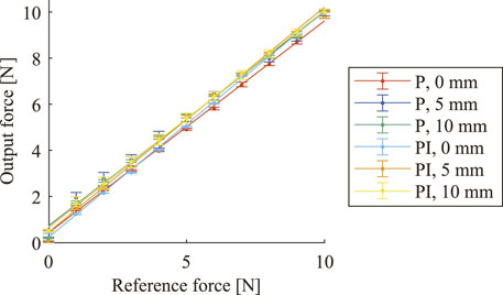
Figure 11. Stimulator’s output force in steady states. The measurement was done at three different stimulator locations. The SEA module to drive the stimulator was controlled either in P (Kp = 14.4 V/N) or PI (Kp = 14.4 V/N, Ki = 48 V/(N s)) control. Measurement was repeated 5 times each. Error bars indicate the minimum and maximum values.
4.3 Dynamic response in the normal direction
Dynamic responses of the normal force control were measured. The stimulator was fixed at 0 mm. A step function that changes from 0 N to 10 N was given to the SEA module controller, and the output force was measured using the spring deformation. The result is shown in Figure 12. The average rise time (from 10% to 90% of the steady-state value) was 0.090 s. While the result for P control shows some steady-state error, the force converges faster than PI control.
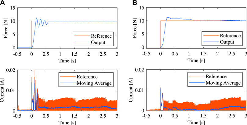
Figure 12. Step response from 0 N to 10 N, measured at stimulator position of 10 mm. (A) P control. (B) PI control.
Although the stimulator position was fixed in the above measurement, it will move in the actual presentation. In the worst case, the stimulator would move for 10 mm to deform the palm. If such a motion is also taken into account, the response time from 0 N (at 0 mm) to 10 N (at 10 mm) was found to increase by about 0.14 s, which is not as expected in the design discussed in Section 3.3. The difference came from the facts: (1) the design assumed that the motor operates at the constant maximum speed, which is not true, especially when the motor is feedback-controlled, and (2) the contact point between the cam and the lever varied during operation (in opposed to the simple design assumption) which extends the moving angle of the gear motor. Since the requirement on the response was not very strict, as discussed in Section 3.3, this difference would not impose severe problems in actual use. However, if a faster response is preferred, the leverage ratio of the lever might be modified since there is some margin in the output force, as depicted in Figure 10. Redesigning the cam could be considered as well. In the designed SEA module, the required force is smaller in the beginning since the springs are not yet contracted. The required force increases as the springs contract. Considering such operation characteristics, the cam profile could be designed such that the speed gradually decrease as the cam rotates.
Figure 12 also shows the current from the DC power source that was used to drive the motor driver. The measured current fluctuated widely due to the PWM control. However, the average curve shows that the average current was kept low in a steady state, even though the output force remains large, which is one of the benefits of the SEA module compared to VCMs used in previous studies.
4.4 Comparison with the VCM device
Table 1 compares several performance metrics for the developed device and the device using VCMs (Asada et al., 2016), which was used in previous studies. The rated output of the previous device was 3.1 N, which is the sum of the rated outputs of the two VCMs (AVM20-10, Technohands Co., Ltd.) used in the device. On the other hand, this device was designed to have 10 N output, which outperforms the previous device. The force/actuator weight compares the SEA module (130 g) with the VCM (177 g), which shows that the developed SEA module has four times larger force density. The power consumption comparison clearly shows the benefit of the developed SEA, which does not require current during constant force output. On the other hand, the output force control’s response time (from 10% to 90% of the steady-state value) is far slower with the developed device.
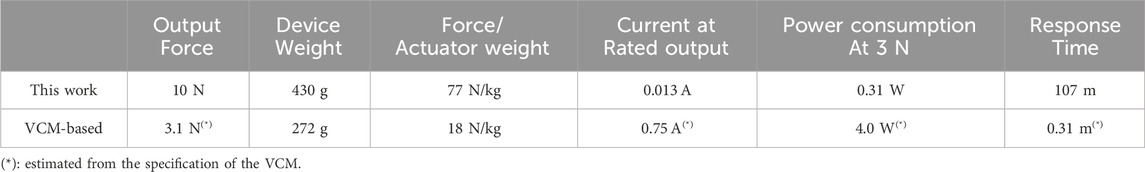
Table 1. Comparison of the developed and previous devices. The previous device utilized two VCMs and the output force used in the table is their total continuous force, while their total peak force is 15.2 N. The output force for the developed device is calculated from the motor’s peak torque. This difference is due to their different operations. While VCMs must keep current during continuous stimulation, the developed device does not require continuous current.
4.5 Human subject experiment: Effect of tangential skin stretch
Finally, using the developed device, skin stretch along the distal/proximal direction on a palm was evaluated on human subjects. The experiment was approved by the Ethics Review Committee of the University of Tokyo (23–310). Four male subjects in their 20s (three right-handed) were recruited in the experimenter’s laboratory. The stimulator location was adjusted to five areas on their palms, as shown in Figure 2. The motion of the stimulator along the normal direction was controlled by the proportional controller, and a force of 7 N was commanded to provide normal pressure to the left-hand palm. Then, the RC servo motor was commanded to rotate the stimulator by
Each time a stimulus was presented, the participants were asked, “Do you feel as if the device is rotating? If yes, in which direction?” The answers are summarized in Table 2. On average, the subjects felt rotations in the intended directions with 94.5% accuracy, indicating that the skin stretch stimulus along the distal/proximal direction can induce a pseudo-torque sensation.

Table 2. Results of human subject study where subjects were provided tangential skin stretch in the proximal/distal direction in either clockwise (CW) or counter-clockwise CCW) directions. The subjects answered in which direction they felt rotation. NR represents the number of answers for which no rotation was felt.
5 Conclusion
Pseudo-force presentation using tactile stimuli is expected to be a powerful tool to enhance reality and operability in VR. Presentations on a palm seem particularly promising, as a palm is always in contact with a controller in an immersive VR setup. To realize 2-DOF pseudo-force/torque presentation to a palm, this paper describes the design of a 2-DOF stimulation device. One of the concerns in developing 2-DOF device is its weight, as 2-DOF structure could be complicated and thus heavy. To realize a lightweight structure, this work adopted series elastic actuator (SEA) using a gear motor for stimulation along the normal direction to the palm surface. Then, another motor rotated the whole SEA module to realize tangential stimulation along the proximal/distal direction.
The paper discusses some requirements for the device to realize stimulation in a wide range of a palm. Using the discussed requirements as a design reference, mechanical elements were selected or designed. In the fabrication, being lightweight was focused rather than precise. The performance of the resulting prototype deviated from the designed values; nevertheless, the prototype realized a satisfactory output force to provide pseudo-force/torque presentation. Using the developed prototype, the effect of tangential skin stretch along the proximal/distal direction was investigated. The result of a subject experiment showed that the skin stretch can invoke a rotational feeling, or pseudo-torque sensation.
In future work, We will investigate the effect of pseudo-force/torque perception in more detail using the developed device. Also, suitable application scenarios will be explored. Some expected scenarios include the operations of a fishing rod (Kojima et al., 2023), motorbike handles, and boat oars, where translational force and rotational torque will occur on palms. Such demonstrations might also be useful for rehabilitation purposes.
Data availability statement
The raw data supporting the conclusions of this article will be made available by the authors, without undue reservation.
Ethics statement
The requirement of ethical approval was waived by the Ethics Review Committee of the University of Tokyo for the studies involving humans because the Ethics Review Committee of the University of Tokyo. The studies were conducted in accordance with the local legislation and institutional requirements. The participants provided their written informed consent to participate in this study. Written informed consent was obtained from the individual(s) for the publication of any potentially identifiable images or data included in this article.
Author contributions
MK: Conceptualization, Formal Analysis, Funding acquisition, Investigation, Methodology, Software, Writing–original draft. SY: Methodology, Supervision, Writing–review and editing. AY: Conceptualization, Funding acquisition, Project administration, Supervision, Writing–review and editing.
Funding
The author(s) declare that financial support was received for the research, authorship, and/or publication of this article. This work was partially supported by JSPS KAKENHI, Grant Number 24K00843 and JST SPRING, Grant Number JPMJSP2108.
Acknowledgments
We appreciate Mr. Roman Oechslin for his contribution in an earlier stage of this project.
Conflict of interest
The authors declare that the research was conducted in the absence of any commercial or financial relationships that could be construed as a potential conflict of interest.
Publisher’s note
All claims expressed in this article are solely those of the authors and do not necessarily represent those of their affiliated organizations, or those of the publisher, the editors and the reviewers. Any product that may be evaluated in this article, or claim that may be made by its manufacturer, is not guaranteed or endorsed by the publisher.
References
Abdi, E., Kulić, D., and Croft, E. (2020). Haptics in teleoperated medical interventions: force measurement, haptic interfaces and their influence on user’s performance. IEEE Trans. Biomed. Eng. 67, 3438–3451. doi:10.1109/TBME.2020.2987603
Amemiya, T., Ando, H., and Maeda, T. (2008). Lead-me interface for a pulling sensation from hand-held devices. ACM Trans. Appl. Percept. 5, 1–17. doi:10.1145/1402236.1402239
Arata, J., Kondo, H., Ikedo, N., and Fujimoto, H. (2011). Haptic device using a newly developed redundant parallel mechanism. IEEE Trans. Robotics 27, 201–214. doi:10.1109/TRO.2010.2098272
Artigas, J., Balachandran, R., Riecke, C., Stelzer, M., Weber, B., Ryu, J.-H., et al. (2016). “Kontur-2: force-feedback teleoperation from the international space station,” in 2016 IEEE International Conference on Robotics and Automation (ICRA), 1166–1173. doi:10.1109/ICRA.2016.7487246
Asada, T., Nakamura, T., and Yamamoto, A. (2016). Investigation on substitution of force feedback using pressure stimulation to palm. IEEE Haptics Symp. 2016 (IEEE), 389–390.
Cakit, E., Durgun, B., Cetik, O., and Yoldas, O. (2014). A survey of hand anthropometry and biomechanical measurements of dentistry students in Turkey. Hum. Factors Ergonomics Manuf. Serv. Industries 24, 739–753. doi:10.1002/hfm.20401
Collins, K., and Kapralos, B. (2019). Pseudo-haptics: leveraging cross-modal perception in virtual environments. Senses Soc. 14, 313–329. doi:10.1080/17458927.2019.1619318
Cooper, N., Milella, F., Pinto, C., Cant, I., White, M., and Meyer, G. (2018). The effects of substitute multisensory feedback on task performance and the sense of presence in a virtual reality environment. PLOS ONE 13, e0191846. doi:10.1371/journal.pone.0191846
Culham, J. C., and Valyear, K. F. (2006). Human parietal cortex in action. Curr. Opin. Neurobiol. 16, 205–212. Cognitive neuroscience. doi:10.1016/j.conb.2006.03.005
Research Institute of Human Engineering for Quality Life (2000). The feeling of weight in one’s hand.
Escobar-Castillejos, D., Noguez, J., Neri, L., Magana, A., and Benes, B. (2016). A review of simulators with haptic devices for medical training. J. Med. Syst. 40, 104–122. doi:10.1007/s10916-016-0459-8
Fujita, K. (2004). Control strategies in human pinch motion to perceive the hardness of an elastic object. Electron. Commun. Jpn. (Part II) Electron. 87, 28–37. doi:10.1002/ecjb.20126
Gibo, T. L., Bastian, A. J., and Okamura, A. M. (2014). Grip force control during virtual object interaction: effect of force feedback, accuracy demands, and training. IEEE Trans. Haptics 7, 37–47. doi:10.1109/TOH.2013.60
Gong, X., Wang, L., Mou, Y., Wang, H., Wei, X., Zheng, W., et al. (2022). Improved four-channel pbtdpa control strategy using force feedback bilateral teleoperation system. Int. J. Control, Automation Syst. 20, 1002–1017. doi:10.1007/s12555-021-0096-y
Guinan, A. L., Montandon, M. N., Doxon, A. J., and Provancher, W. R. (2014). “Discrimination thresholds for communicating rotational inertia and torque using differential skin stretch feedback in virtual environments,” in 2014 IEEE haptics symposium (HAPTICS) (Houston, TX: IEEE), 277–282. doi:10.1109/haptics.2014.6775467
Guzererler, A., Provancher, W. R., and Basdogan, C. (2016). “Perception of skin stretch applied to palm: effects of speed and displacement,” in Haptics: perception, devices, control, and applications. Editors F. Bello, H. Kajimoto, and Y. Visell (Cham: Springer International Publishing), 180–189.
Hachisu, T., Cirio, G., Marchal, M., Lécuyer, A., and Kajimoto, H. (2011). “Pseudo-haptic feedback augmented with visual and tactile vibrations,” in 2011 IEEE international symposium on VR innovation, 327–328. doi:10.1109/ISVRI.2011.5759662
Hajian, A. Z., and Howe, R. D. (1997). Identification of the mechanical impedance at the human finger tip. J. Biomechanical Eng. 119, 109–114. doi:10.1115/1.2796052
Hall, N. B., and Bennett, E. M. (1956). Empirical assessment of handrail diameters. J. Appl. Psychol. 40, 381–382. doi:10.1037/h0042873
Hayward, V., Astley, O. R., Cruz-Hernandez, M., Grant, D., and Robles-De-La-Torre, G. (2004). Haptic interfaces and devices. Sens. Rev. 24, 16–29. doi:10.1108/02602280410515770
Kojima, M., Yoshimoto, S., and Yamamoto, A. (2022). “Evaluation of point of subject equality using constant method in pseudo force sensation by pressure stimulation to the palm,” in 2022 31st IEEE international conference on robot and human interactive communication (Napoli, Italy: RO-MAN), 205–210. doi:10.1109/RO-MAN53752.2022.9900745
Kojima, M., Yoshimoto, S., and Yamamoto, A. (2023). “Grip-type pseudo force display with normal and tangential skin stimulation,” in New trends in medical and service robotics. Editors D. Tarnita, N. Dumitru, D. Pisla, G. Carbone, and I. Geonea (Cham: Springer Nature Switzerland), 63–70. doi:10.1007/978-3-031-32446-8_7
Kong, Y.-K., and Lowe, B. D. (2005). Optimal cylindrical handle diameter for grip force tasks. Int. J. Industrial Ergonomics 35, 495–507. doi:10.1016/j.ergon.2004.11.003
Lopes, P., You, S., Ion, A., and Baudisch, P. (2018). “Adding force feedback to mixed reality experiences and games using electrical muscle stimulation,” in Proceedings of the 2018 CHI Conference on Human Factors in Computing Systems (New York, NY, USA: Association for Computing Machinery), 1–13. CHI ’18. doi:10.1145/3173574.3174020
Mansour, M. A. (2016). Hand anthropometric data for Saudi Arabia engineering students of aged 20-26 years at king khalid university. Am. J. Eng. Appl. Sci. 9, 877–888. doi:10.3844/ajeassp.2016.877.888
Martin, D., Malpica, S., Gutierrez, D., Masia, B., and Serrano, A. (2022). Multimodality in vr: a survey. ACM Comput. Surv. 54, 1–36. doi:10.1145/3508361
Miyasato, T., and Nakatsu, R. (1997). “Allowable delay between images and tactile information in a haptic interface,” in Proceedings. International conference on virtual systems and MultiMedia VSMM ’97 (cat. No.97TB100182), Geneva, Switzerland (IEEE), 84–89. doi:10.1109/VSMM.1997.622334
Moya, V., Slawiñski, E., and Mut, V. (2021). Delayed teleoperation with force feedback of a humanoid robot. Int. J. Automation Comput. 18, 605–618. doi:10.1007/s11633-020-1267-7
Nakamura, T., Nemoto, S., Ito, T., and Yamamoto, A. (2018). “Substituted force feedback using palm pressurization for a handheld controller,” in Haptic interaction. Editors S. Hasegawa, M. Konyo, K.-U. Kyung, T. Nojima, and H. Kajimoto (Singapore: Springer Singapore), 197–199.
Okunribido, O. O. (2000). A survey of hand anthropometry of female rural farm workers in ibadan, western Nigeria. Ergonomics 43, 282–292. doi:10.1080/001401300184611
Patel, R. V., Atashzar, S. F., and Tavakoli, M. (2022). Haptic feedback and force-based teleoperation in surgical robotics. Proc. IEEE 110, 1012–1027. doi:10.1109/JPROC.2022.3180052
Pratt, G., and Williamson, M. (1995). Series elastic actuators. Proc. 1995 IEEE/RSJ Int. Conf. Intelligent Robots Syst. Hum. Robot Interact. Coop. Robots 1, 399–406. doi:10.1109/IROS.1995.525827
Prattichizzo, D., Pacchierotti, C., Cenci, S., Minamizawa, K., and Rosati, G. (2010). “Using a fingertip tactile device to substitute kinesthetic feedback in haptic interaction,” in Haptics: generating and perceiving tangible sensations. Editors A. M. L. Kappers, J. B. F. van Erp, W. M. Bergmann Tiest, and F. C. T. van der Helm (Berlin, Heidelberg: Springer Berlin Heidelberg), 125–130.
Ramsamy, P., Haffegee, A., Jamieson, R., and Alexandrov, V. (2006). “Using haptics to improve immersion in virtual environments,” in Computational science – ICCS 2006. Editors V. N. Alexandrov, G. D. van Albada, P. M. A. Sloot, and J. Dongarra (Berlin, Heidelberg: Springer Berlin Heidelberg), 603–609. doi:10.1007/11758525_81
Rassi, I. E., and Rassi, J.-M. E. (2020). A review of haptic feedback in tele-operated robotic surgery. J. Med. Eng. Technol. 44, 247–254. doi:10.1080/03091902.2020.1772391
Sakaniwa, H., Tajiri, R., Takano, M., Miyaki, M., Uwa, Y., Yoshimoto, S., et al. (2021). Improved tilt feeling during remote control of construction machine by tactile sensation. J. Adv. Comput. Intell. Intelligent Inf. 25, 365–374. doi:10.20965/jaciii.2021.p0365
Schorr, S. B., and Okamura, A. M. (2017). Three-dimensional skin deformation as force substitution: wearable device design and performance during haptic exploration of virtual environments. IEEE Trans. Haptics 10, 418–430. doi:10.1109/toh.2017.2672969
Shim, Y. A., Park, K., Lee, S., Son, J., Woo, T., and Lee, G. (2020). “Fs-pad: video game interactions using force feedback gamepad,” in Proceedings of the 33rd annual ACM symposium on user interface software and Technology (New York, NY, USA: Association for Computing Machinery), 938–950. UIST ’20. doi:10.1145/3379337.3415850
Silva, A. J., Ramirez, O. A. D., Vega, V. P., and Oliver, J. P. O. (2009). “Phantom omni haptic device: kinematic and manipulability,” in 2009 electronics, robotics and automotive mechanics conference (Cuernavaca, Mexico: CERMA), 193–198. doi:10.1109/CERMA.2009.55
Stone, R. J. (2001). “Haptic feedback: a brief history from telepresence to virtual reality,” in Haptic human-computer interaction. Editors S. Brewster, and R. Murray-Smith (Berlin, Heidelberg: Springer Berlin Heidelberg), 1–16.
Ujitoko, Y., and Ban, Y. (2021). Survey of pseudo-haptics: haptic feedback design and application proposals. IEEE Trans. Haptics 14, 699–711. doi:10.1109/TOH.2021.3077619
Vicentini, M., Galvan, S., Botturi, D., and Fiorini, P. (2010). Evaluation of force and torque magnitude discrimination thresholds on the human hand-arm system. ACM Trans. Appl. Percept. 8, 1–16. doi:10.1145/1857893.1857894
Wei, T.-Y., Tsai, H.-R., Liao, Y.-S., Tsai, C., Chen, Y.-S., Wang, C., et al. (2020). “Elastilinks: force feedback between vr controllers with dynamic points of application of force,” in Proceedings of the 33rd annual ACM symposium on user interface software and Technology (New York, NY, USA: Association for Computing Machinery), 1023–1034. UIST ’20. doi:10.1145/3379337.3415836
Whitaker, T. A., Simões-Franklin, C., and Newell, F. N. (2008). Vision and touch: independent or integrated systems for the perception of texture? Brain Res. 1242, 59–72. Multisensory Integration. doi:10.1016/j.brainres.2008.05.037
Yakou, T., Yamamoto, K., Koyama, M., and Hyodo, K. (1997). Sensory evaluation of grip using cylindrical objects. JSME Int. J. Ser. C 40, 730–735. doi:10.1299/jsmec.40.730
Yoshimoto, S., and Yamamoto, A. (2021). Pressure stimulus to the palm substitutes and augments force sensation. IEEE Trans. Haptics 14, 930–935. doi:10.1109/TOH.2021.3087230
Zheng, Y., and Mak, A. (1997). “Extraction of effective young’s modulus of skin and subcutaneous tissues from manual indentation data,” in Proceedings of the 19th Annual International Conference of the IEEE Engineering in Medicine and Biology Society (Chicago, IL: ‘Magnificent Milestones and Emerging Opportunities in Medical Engineering’ Cat. No.97CH36136), 2246–2249. doi:10.1109/IEMBS.1997.758807
Keywords: pseudo-haptics, pseudo-force, pseudo-torque, normal pressure, skin stretch, device design, palm, series elastic actuators
Citation: Kojima M, Yoshimoto S and Yamamoto A (2024) Design of a haptic device for presenting pressure and skin stretching stimuli to the palm. Front. Mech. Eng 10:1417881. doi: 10.3389/fmech.2024.1417881
Received: 15 April 2024; Accepted: 28 June 2024;
Published: 29 July 2024.
Edited by:
Wenyu Liang, Institute for Infocomm Research (A∗STAR), SingaporeReviewed by:
Andrea Botta, Polytechnic University of Turin, ItalyZeyu Lu, National University of Singapore, Singapore
Copyright © 2024 Kojima, Yoshimoto and Yamamoto. This is an open-access article distributed under the terms of the Creative Commons Attribution License (CC BY). The use, distribution or reproduction in other forums is permitted, provided the original author(s) and the copyright owner(s) are credited and that the original publication in this journal is cited, in accordance with accepted academic practice. No use, distribution or reproduction is permitted which does not comply with these terms.
*Correspondence: Mayuka Kojima , a29qaW1hQGFtbC50LnUtdG9reW8uYWMuanA=