 Jingjing Feng
- Department of Electrical and Electronic Engineering, Suzhou College of Information Technology, Suzhou, China
Introduction: Nowadays, five-phase permanent magnet synchronous motors have been widely used in the industrial and transportation fields, and the existing sliding mode control methods for speed control systems can no longer meet the requirements such as fast response and good stability.
Methods: In light of the aforementioned considerations, the study initially employs mathematical modeling to elucidate the five-phase permanent magnet synchronous motor. Secondly, on the basis of proportional-integral-derivative sliding mode control, radial basis function and Takagi-Sugeno-Kang fuzzy model are introduced for parameter identification and optimization and regulation. Finally, a new neural network regulation algorithm and speed control strategy are proposed.
Results and Discussion: The experimental results demonstrated that the expected parameter optimization rate of the regulation algorithm can reach 90%, and the overshooting amount under small inertia working condition is only 3%, and the adjustment time is 0.02 s. The new control algorithm can be used to control the motor speed with the lowest speed fluctuation and the fastest recovery time. In addition, when affected by the load torque, the motor speed controlled by the new strategy fluctuated the least, with a speed drop of only 1% and the fastest recovery time of 0.02 s. It exhibited the lowest control error of 3.7% and the lowest overshooting amount of 5.9%.
Conclusion: In summary, the suggested approach has the potential to significantly enhance the speed control system’s control performance while maintaining strong resilience and anti-interference capabilities. The method has certain guiding significance for the practical application of five-phase permanent magnet synchronous motor speed control system.
1 Introduction
Five-phase Permanent Magnet Synchronous Motor (FPMSM) has become an indispensable power source in industrial automation and modern transportation systems due to its high efficiency and excellent performance (Xu et al., 2020). With the advancement of technology and the growth of industrial demands, the need for precise control of motor speed control systems is increasing, and the selection of appropriate control strategies becomes particularly critical. Although conventional control methods, such as smooth-mode control, have been widely used in these systems, they often exhibit performance degradation in response to variations in system parameters and external perturbations, which poses a significant challenge in maintaining system responsiveness and stability (Hou et al., 2020; Xu et al., 2021). To solve this problem, numerous researchers have tried various control strategies, including empirical, trial-control and optimization methods, to improve the parameter settings of the sliding mode controller. Among the aforementioned methods, the empirical and trial-control methods rely on experimentation and debugging to obtain the initial values of the controller parameters. However, these methods are not only complicated to operate, but also have limited effects. Currently, the optimization method mainly solves for the optimal controller parameters under specific performance indexes through algorithms. Nevertheless, its parameter tuning remains challenging in the face of nonlinear and changing system environments (Liu et al., 2020). Therefore, the study innovatively proposes an improved Proportional-Integral-Derivative (PID) sliding mode control method by introducing machine learning optimization techniques, especially Radial basis function algorithm (RBF) and Takagi-Sugeno-Kang (TSK) fuzzy model. Derivative, PID) sliding mode control method. The method aims to significantly improve the performance and adaptability of FPMSM speed control system. This research is divided into four parts, the first part is the analysis and summary of others’ research, the second part describes how the FPMSM mathematical model and parametric fuzzy regularization strategy are constructed, respectively, while the third part tests the performance of this new method, and the last part concludes the article.
2 Related works
With the benefits of high torque precision, high power density, and high efficiency, FPMSM is a novel kind of high-performance motor. Due to its nonlinear and coupling characteristics, the study of SMC strategy for its SCS is of great significance. In order to explore a novel SMC strategy for FPMSM speed regulation, Sun et al. (2022) proposed a speed decoupling control strategy after combining dual-frequency vector modulation. The experimental results showed that the effectiveness of the strategy in the simulation test trial set was high and the control accuracy was good (Sun et al., 2022). Li et al. (2022) found that in field-oriented controlled FPMSM drives, the current sensors may fail in harsh operating environments, which can lead to data diagnostic crashes in the motor SCS. Therefore, the research team proposed a novel SCS current sensor fault-tolerant control strategy after combining the theory of third harmonic control. Experimental results showed that the strategy has good control robustness over the entire speed range (Li et al., 2022). To explore a new FPMSM SMC PT strategy, Mossa et al. (2022) proposed a novel vector controller for the drive after combining sliding mode and adaptive system. The experimental results demonstrated that this controller has better enhancement performance and is able to reduce the deviation between resistance and stator inductance compared to a single adaptive system (Mossa et al., 2022). Junejo et al. (2020) suggested a new adaptive terminal sliding mode convergence law to enhance the speed control performance of FPMSM under internal and external disturbances. The experimental results indicated that this new convergence law significantly outperforms the conventional convergence law on the Lyapunov function and is more feasible (Junejo et al., 2020).
Parameter fuzzy tuning refers to the adjustment of the control parameters of a system so that it can maintain stable operation or meet predetermined performance requirements under uncertain environmental conditions. Due to the complexity and variability of FPMSM’s PT, the appropriate parameters need to be determined based on the characteristics and control requirements of the specific system. Hussain discovered that in vector controlled permanent magnet synchronous motor drives, it is challenging to set the current control parameters. Consequently, the researcher suggested a generalized PT design approach. The method’s applicability and robustness in terms of tracking, disturbance suppression, and noise sensitivity were demonstrated by the experimental results (Hussain, 2020). Bi et al. (2022) concluded that optimizing control parameters is important for the high-performance operation of FPMSM drives. Therefore, they proposed a parameter self-correction method after combining multi-objective optimization and online tracking. The experimental results demonstrated that this method is more capable of realizing the online tracking of control and observation parameters compared to the traditional PT method (Bi et al., 2022). Li et al. (2021) found that the dependence of differential beat-free predictive current control on the accuracy of FPMSM parameters is the main obstacle to its wide application. They therefore suggested a novel control strategy in order to address the issue. According to the experimental data, this strategy was significantly more effective than other conventional methods under complex parameter mismatch settings (Li et al., 2021). Xia J. et al. (2020) concluded that there are abnormal perturbations in the electrical and mechanical parameters of the FPMSM under different operating conditions, which can greatly degrade the control performance. Therefore, they proposed a robust control strategy with parameter adaptation. Experimental results demonstrated that this strategy can realize robust regulation of stator current and rotor speed while accurately estimating the machine parameters (Xia J. et al., 2020).
In conclusion, researchers both domestically and internationally have investigated the SCS SMC of motors and the PT within FPMSM to varying degrees in recent years, and they have suggested several useful control schemes and PT techniques. However, with the development of technology, the traditional PT method of SMC can no longer meet the demand, therefore, the research tries to innovate the fuzzy rectification of the parameters of the SCS SMC of FPMSM, and innovatively improves the RBF and the TSK jointly, which is used to optimize the parameter control of the PID SMC.
3 Fuzzy improved neural network-based parameter tuning for smooth mode control of motor speed control
To construct a reasonable PT method for SMC of motor speed control, the study firstly performs mathematical modeling for FPMSM under hypothetical state. Secondly, the traditional PID SMC is optimized, and the RBF algorithm is introduced for parameter identification. Finally, a TSK fuzzy neural network is incorporated for PT calculation and a novel FPMSM motor speed SMC strategy is proposed.
3.1 Mathematical modeling of FPMSM for vector control
FPMSM is a synchronous motor that uses permanent magnet material as an excitation source. It generates a rotating magnetic field through five sets of coils on the stator, which interacts with the magnetic field of the permanent magnets on the rotor to achieve the rotation of the rotor (Long et al., 2020; Yang et al., 2021). Its SCS is characterized by high order, nonlinearity and strong coupling. The physical and topological structure of FPMSM is shown in Figure 1.
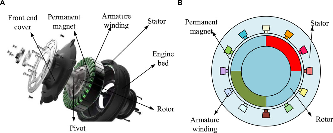
Figure 1. The physical and topological structure of FPMSM. (A) FPMSM physical image (B) FPMSM profile topology.
Figure 1A shows the physical view of the FPMSM and Figure 1B shows the sectional topology of the FPMSM. In Figure 1, the rotor surface is covered with tile-like permanent magnets, while the rotor itself is not configured with windings (Choudhuri et al., 2023). In the stator slot, the layout of the five-phase centralized windings expresses the independence of the magnetic circuits between the phases through mathematical modeling. Specifically, the coupling coefficients between the inductances of each phase are minimized by a sophisticated physical design, which effectively reduces mutual inductance and thus improves the accuracy of the model (Zhao et al., 2021). In addition, the slotting effect is usually ignored in the general model simplification because it introduces additional harmonics which increase electromagnetic noise and vibration and reduce the smoothness of the motor operation. On the contrary, magnetic circuit saturation is taken into account, which has a significant effect on the electromagnetic characteristics of the motor. A nonlinear magnetic circuit model is used in motor design to approximate the magnetic circuit saturation, taking into account its effect on efficiency and output torque. This nonlinear analysis helps to improve the prediction accuracy of the model under high load conditions. Therefore, the study, in order to simplify the analysis, adopts a hypothetical treatment, i.e., it assumes that the motor of the FPMSM is star connected and symmetrical, while ignoring the effects brought about by the conductivity of the permanent magnets, core saturation, and hysteresis and eddy currents. At this stage, the FPMSM is equivalently represented in terms of Pike’s matrix and Clark’s matrix for the stationary coordinate system (CS) and the natural CS, respectively. Where the voltage equation in the natural CS is shown in Eq. 1.
In Eq. 1,
In Eq. 2,
In Eq. 3,
In Eq. 4,
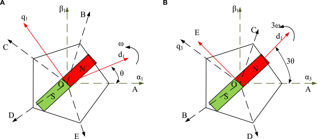
Figure 2. Schematic diagram of spatial coordinate system for fundamental and third harmonic waves. (A) Fundamental wave space (B) Third harmonic space.
In Figure 2,
In Eq. 5,
Eqs 5, 6 describe the vector control strategy for the five-phase motor in detail, including its mathematical derivation and implementation details. The control algorithm then utilizes the Pike and Clark matrices for coordinate transformation to accurately control the amplitude and phase of the current to achieve precise regulation of the electromagnetic torque. The equations for the stationary CS voltage and EMT at this point after transformation are shown in Eq. 7.
The stationary CS voltages at this point after transformation and in Eq. 7,
3.2 Parameter tuning for fuzzy improved RBF-based sliding mode PID control
Sliding mode PID control is an advanced control strategy that combines the robustness of SMC with the simplicity of PID control, and this control method is particularly effective in dealing with uncertainty and nonlinear systems (Xia X. et al., 2020; He et al., 2020). Nevertheless, at specific instances, the fixed and unchanging control parameters are unable to fulfill the demands of working conditions with high requirements. Consequently, the study selects the more classical RBF algorithm for nonlinear data fitting approximation, with the objective of compensating for the shortcomings of Sliding Mode PID control. In Figure 3, the RBF network structure is displayed (Zheng et al., 2022).
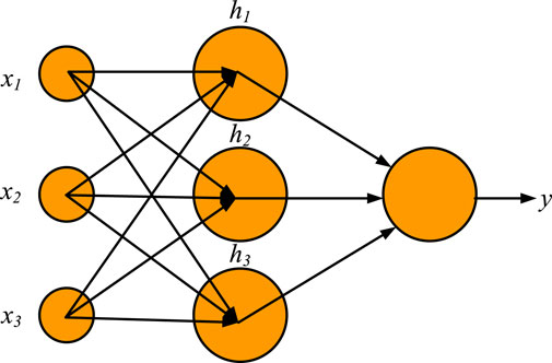
Figure 3. The network structure diagram of RBF.
The approach in Figure 3 transfers the input space to a high-dimensional feature space, which allows for the linear divisibility of a linearly indivisible issue (He et al., 2022). In PID for SMC, the RBF infinitely approximates the optimal sliding mode PID control scheme by continuously correcting its own output weights, centroid positions and expansion constants. Where the correction equation of RBF in gradient descent method for each node parameter is shown in Eq. 8.
In Eq. 8,
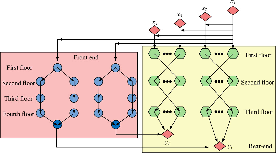
Figure 4. The structural topology of TSK fuzzy neural network.
In Figure 4, the whole TSK fuzzy neural network can be divided into a front-end with fuzzy rule storage and a back-end composed of constructing fuzzy rules. It has an input layer, a fuzzification layer, a rule layer, a defuzzification layer, and an output layer. It also incorporates neural network and TSK fuzzy model features (Abbassi et al., 2023). Data is fed into the input layer, which then fuzzifies it into fuzzy values, applies fuzzy logic rules, defuzzifies the rule output, packages it, and outputs findings that are easy to understand. This structure makes the network suitable for dealing with complex nonlinear problems with good interpretability. Where the fuzzification layer is calculated as shown in Eq. 9.
In Eq. 9,
In Eq. 10, both
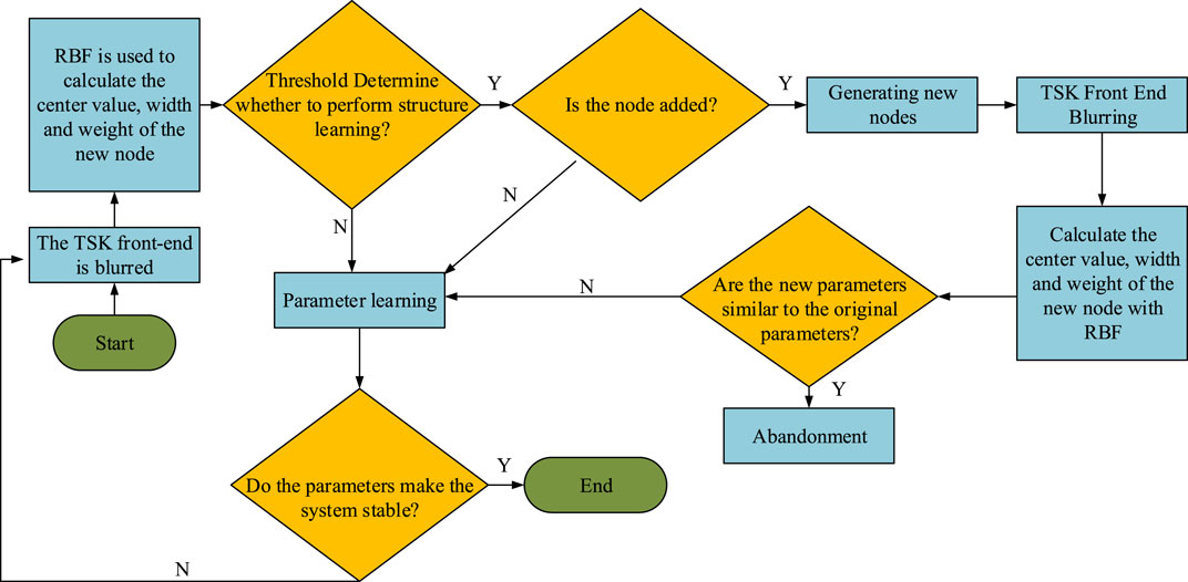
Figure 5. The self-learning process of TSK fuzzy network.
In Figure 5, the initial data is first input to the front end of the TSK for fuzzification operation, while the center value calculation, width calculation and weight calculation of the first data are performed by the node parameter correction and approximation equations of the RBF neural network. At this point, these parameters are compared in the form of threshold judgment, if it is greater than the threshold then structure learning is performed, otherwise parameter learning is performed. After structure learning a new node is generated and the new node repeats the fuzzification operation and RBF parameter approximation calculation again. If the new parameters at this time are similar to the initial parameters, the new node is removed, unless the parameters are significantly different, then it is chosen to be retained and parameter learning is performed along with the previous parameters. Finally, if these learned parameters are able to make the motor SCS stabilized then the parameters are output, otherwise the first step of the computation is repeated. The study proposes a novel parametric controller for sliding mode control of FPMSM speed control system, i.e., TSK-RBF-PID speed sliding mode controller. The control system is divided into three main parts, i.e., RBF parameter optimization module, TSK fuzzy neural network parameter tuning module, and PID speed controller. The flow of the model starts with five current signals output from the motor, which are first converted into digital signals by an analog-to-digital converter, i.e., ADC. The digital signal is processed by the Clark transform to obtain two orthogonal current components
In addition, the model includes a feedback link where the difference between the actual speed of the motor and the set speed is calculated by the error detector and processed by the PID controller. Meanwhile, RBF parameter optimization and TSK fuzzy neural network are used to optimize the performance of the PID controller to ensure fast and accurate system response (Bensalem et al., 2021). The feedback control of the speed is done by a PID controller which optimizes the system response based on the speed error and its differentials. The RBF passes the optimized parameter information to the TSK fuzzy neural network for computation and finally feeds back to the PID controller for parameter updating and real-time control of FPMSM is implemented. Where the formula for the speed error is shown in Eq. 11.
In Eq. 11,
The proportional gain, integral gain, and differential gain at the current time
In Eq. 13,
4 Experimental test
The experimental platforms for performance test and simulation test are built respectively, and firstly, the performance test is carried out for the software algorithm part in the TSK-RBF-PID Speed SMC to compare with the same type of algorithmic model. Secondly, simulation tests are conducted on the TSK-RBF-PID controller to detect the parameter changes under different operating conditions.
4.1 TSK-RBF-PID speed sliding mode control performance test
The study starts with testing the TSK-RBF algorithm in TSK-RBF-PID Speed SMC. The operating system is set to Windows, the CPU is set to Intel Core i7, the GPU is NVIDIA RTX 1660s, and the memory is 16GB. The simulation modeling is implemented in MATLAB software, the momentum factor is set to 0.1, and the learning rate is 0.01. As the source of the test data, the PMSM dataset, a publicly available dataset used for motor troubleshooting, is selected. The public dataset contains the values of parameters such as rotational speed, torque, current, voltage, etc. Of the motor in normal state and fault state. It is divided into training and test sets according to the ratio of 8:2, while PT neural network algorithms that are more popular at this stage of FPMSM, such as Back Propagation (BP) neural network, RBF neural network, and Extreme Learning Machine (ELM), continue to be introduced. The algorithms are selected for their exemplary performance and adaptability in motor control. Among them, the BP network is well-suited for complex nonlinear mapping, the RBF network for rapid learning in real-time control, and the ELM is particularly suitable for rapid deployment. Additionally, the study optimizes the network parameters, such as the learning rate and the number of nodes, through cross-validation to ensure adaptation to the specific system dynamics, which yields the optimal performance of each algorithm. The parameter values of the PID speed controller are fixed, the target speed is set to 1,600 r/min, and 0–0.3 s is specified as the no-load start-up phase, and after 0.3 s as the stable output phase. Observe the change value of the motor speed curve under different algorithm models, and the specific test results are shown in Figure 6.
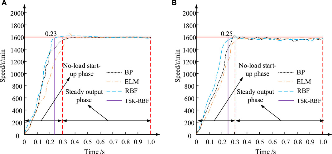
Figure 6. Comparison results of motor speed under different algorithm models. (A) Training set (B) Test set.
Figure 6A shows the variation curves of motor speed controlled by four different algorithms in the training set, and Figure 6B shows the variation curves of motor speed controlled by four different algorithms in the test set. From Figure 6, in the speed increase stage of the test set, the speed increase slope of TSK-RBF is the largest, and its fastest time to reach the target speed is 0.25 s. Although the slope of the training set is slightly lower than that of the separate RBF algorithm, the speed performance of TSK-RBF has been stable in the stabilized output stage, whereas the RBF leads to some fluctuations in the motor operation in the later stage due to the increase in the amount of overshooting. The rationale for this is that the TSK-RBF algorithm considers a greater number of system characteristics and dynamic changes during training, which enables more precise control of the motor speed and avoids unnecessary fluctuations during the testing phase. The study tested the expected parameter optimization with the better performing RBF and TSK-RBF, and the comparative results of the parameter optimization of the two algorithms are shown in Figure 7.
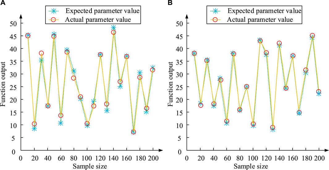
Figure 7. Comparison results of expected optimization of motor parameters using two algorithms. (A) RBF (B) TSK-RBF.
The expected and actual parameters of the RBF algorithm are compared in Figure 7A, and the outcomes of the TSK-RBF algorithm’s comparison are compared in Figure 7B. In Figure 7, relatively speaking, among the 20 parameter optimization objective values, the RBF algorithm only exhibits a parameter optimization rate of 50%, which is manifested by the low overlap between the expected and real parameters. On the contrary, the TSK-RBF algorithm proposed in the study has a parameter optimization rate of up to 90%. As the sample size increases, the degree of overlap between the expected and true parameters of the sample also increases significantly. This is due to the fact that the TSK-RBF technique is typically capable of modifying the TSK model’s parameters and the RBF neural network’s weights in real time, thereby improving the performance of adaptive speed regulation. In order to quantify the index performance effect under different algorithms, the study is conducted to compare the small and large inertia, i.e., the rotational inertia of the SCS is 2 × 10⁻⁵kg-m2 and 5 × 10⁻⁵kg-m2 as the established conditions, respectively, and the overshooting amount and the regulation time are taken as the indexes. To provide a comprehensive comparison, the most cutting-edge technology currently available in the field, namely, literature 18, is also included in the test. The results of this comparison are presented in Table 1.
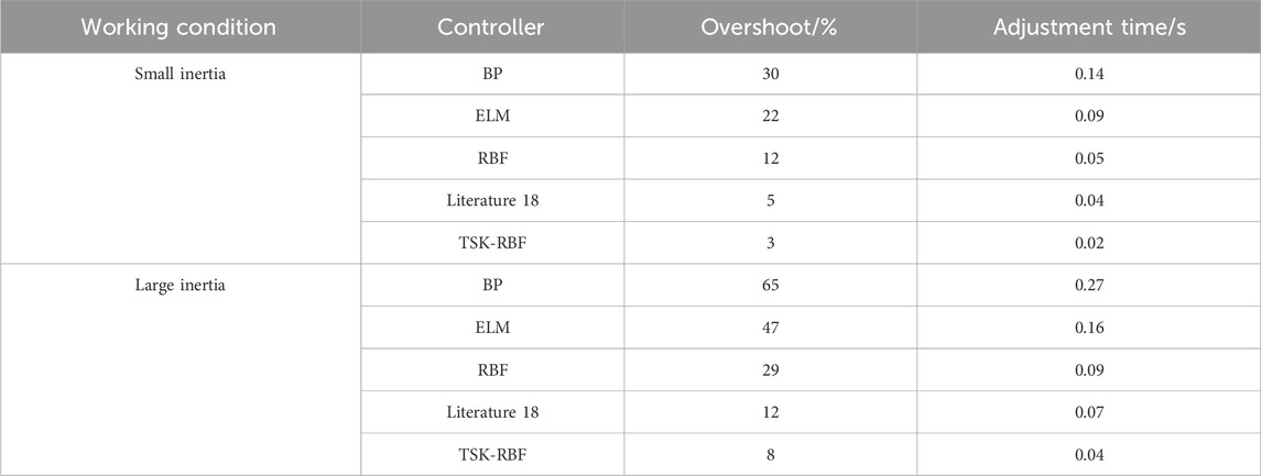
Table 1. Test results of indicators for different algorithm controllers.
As illustrated in Table 1, the Literature 18 proposed method exhibits superior performance in terms of both overshooting and adjustment time data when compared to BP and ELM. However, collectively, TSK-RBF demonstrates the most advantageous performance. Under small inertia conditions, the TSK-RBF controller overshoots by only 3% with a tuning time of 0.02 s, indicating that it provides the fastest system stability and the smallest overshoot under small inertia conditions. Under large inertia conditions, the TSK-RBF controller again performs best, with a significant drop in overshoot to 8%. The tuning time is 0.04 s. The rationale for this is that TSK-RBF enables the controller to predict and adjust to the optimal control parameters with greater precision. In this instance, the TSK model provides fine fuzzy logic control that automatically adjusts the control rules in accordance with the system dynamics. Furthermore, the RBF network optimizes the control parameters through its learning ability, particularly when the system load or dynamics change significantly, in order to facilitate rapid adaptation and the reduction of overshooting. The preceding data demonstrate that the TSK-RBF controller exhibits robust performance under diverse operational scenarios, particularly in the context of systems with substantial inertia. The lower overshoot means more precise control, and the shorter adjustment time indicates that the system is more responsive and can reach a steady state more quickly.
4.2 TSK-RBF-PID speed sliding mode control simulation test
The study used Matlab platform to build the controller of TSK-RBF-PID, in which the TSK fuzzy neural network is realized by sigmiod function. The network’s learning rate is fixed at 0.05, its integral coefficient is 0.813, and its proportional coefficient in the PI coefficients is 2.615. The model of the motor used for the test is 6SZW40-90-15, the rated torque is 10T/(N-m), the rated rotational speed is set to 2700n/(r/min), the rotational moment of inertia is 0.0184J/(kg-m2), and the stator resistance is 2.15L/mH. Two different working conditions are set for the study, working condition 1 is set with a rated speed of 1,600 r/min and a load of 10N-m pair is applied abruptly at 0.5 s. Condition 2 sets the rated speed to 1,600 r/min and changes the speed to 1,900 r/min at 0.5 s. Comparative tests of simple PID control, RBF neural network control, TSK-RBF fuzzy neural network control and TSK-RBF-PID control are carried out through the two conditions, and the results of the tests are shown in Figure 8.
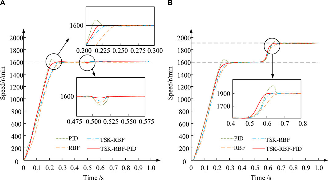
Figure 8. Comparative testing of different control methods under two operating conditions. (A) Working condition 1 (B) Working condition 2.
The test results of the four control techniques in Condition 1 are displayed in Figure 8A, and the test results of the four control methods in Condition 2 are displayed in Figure 8B. The TSK-RBF-PID may initially and smoothly reach the normal goal speed in Figure 8A in 0.22 s. The next is the TSK-RBF control method with 0.23 s, and the slowest is the PID control method with 0.235 s. In addition, when the load is suddenly applied in the 0.5 s, the speed fluctuates the most for the PID control method with the speed decreasing by about 6%, and the recovery time is the longest at 0.08 s. Comparatively speaking, the TSK-RBF-PID control method has the smallest fluctuation, with a speed decrease of only 1% and the fastest recovery time of 0.02 s. The preceding results demonstrate that the combination of RBF and TSK optimizes the control strategy, enabling the controller to react promptly to sudden load or parameter changes and to rapidly restore the steady state. Furthermore, the study plots the current change curves of the four control techniques under the condition of working condition 1 to more graphically demonstrate the performance effect of various control methods, as illustrated in Figure 9.
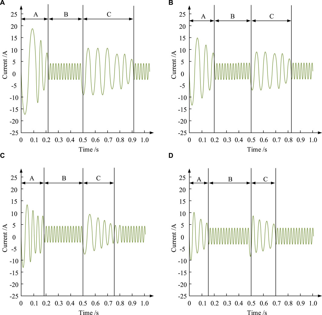
Figure 9. Current variation curves under different control methods. (A) PID (B) RBF (C) TSK-RBF (D) TSK-RBF-PID.
Figures 9A, B, C, D depict the current variation curves under PID, RBF, TSK, and TSK-RBF control methods, respectively. They also depict the current variation curves under TSK-RBF-PID and TSK-RBF-RBF control methods. Where stage A is the motor start-up stage, stage B is the motor stable operation stage, and stage C is the recovery stage after impact. In Figure 9 in stage A, the TSK-RBF-PID control method shows a much smaller current variation, stabilized in the range of –10A–10A, and its shortest time is 0.15 s. In stage B, from all four control methods show a more stable current. When the load is added at the beginning of 0.5 s, the current of the TSK-RBF-PID control method still fluctuates in the range of −10A–10A, and its current state recovery time is the shortest of 0.2 s, which is nearly half of the data compared with the 0.4 s of the PID control method. The final study introduces hardware rolling bearings as test artifacts, employing control error and overshoot as reference indicators. Additionally, a new working condition environment is introduced to enhance the comprehensiveness of the test, designated as working Condition 3. The rated rotational speed is maintained at 1,600 r/min throughout the entirety of the process in working Condition 3. A total of five cycles of testing are conducted for each of the four control methods under the three working conditions, and the test results are presented in Table 2.
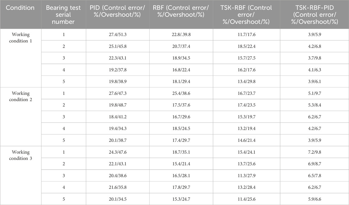
Table 2. Indicator test results of rolling bearings under different control methods.
Table 2 illustrates that the TSK-RBF-PID control method exhibits the lowest control error among the four methods under working Condition 1, with a value of 3.7%. Additionally, its overshoot is the lowest among the methods, at 5.9%. This represents a notable decrease in overshoot compared to the other methods. In Condition 2, the TSK-RBF-PID control method also demonstrates superior performance, with the lowest control error of 3.9% and the lowest overshoot of 5.9%. In accordance with Condition 3, the TSK-RBF-PID control method continues to demonstrate optimal performance, with a control error of 5.9% and an overshoot of 6.6% representing the lowest values observed. In conclusion, following numerous cycles of rolling bearing production tests, it has been demonstrated that the TSK-RBF-PID control method exhibits clear advantages in performance compared to other methods under these two operating conditions. Furthermore, it is more suitable for sliding mode control of FPMSM speed control systems at this stage.
5 Conclusion
SMC is frequently utilized in the study of SCSs for FPMSM in order to enhance the system’s control performance. However, due to the nonlinearity and complexity of the SCS of FPMSM, the conventional SMC method may suffer from performance degradation in some cases. In light of the aforementioned considerations, the study employs Clark and Pike transformations to construct a mathematical model of FPMSM. Furthermore, the parameter parameterization of PID control is optimized through the integration of a RBF neural network and TSK fuzzy neural network. The experimental results demonstrated that the TSK-RBF control algorithm exhibits the greatest slope of motor speed increase and the fastest time to reach the target speed, with a rate of up to 90% for expected parameter optimization. Furthermore, the overshooting amount of the TSK-RBF controller in a small inertia working condition was only 3%, with a tuning time of 0.02 s. The TSK-RBF-PID control method exhibited minimal speed fluctuations in the presence of load torque, with a maximum speed drop of only 1% and the fastest recovery time of 0.02 s. Comparing with the same type of control methods, it was found that the TSK-RBF-PID controller had the lowest control error of 3.7%, the lowest overshooting amount of 5.9%. In conclusion, the TSK-RBF-PID control method not only enhances the adaptive capability of the control system, but also ensures high accuracy and fast response in a variable industrial environment. In addition, there are still some limitations in studying the proposed method, such as the effect of the added parameter tuning in the TSK fuzzy neural network on the real-time performance, which may affect the real-time performance of the controller. Future research could focus on optimizing the network structure and learning algorithm to reduce the required parameter adjustments and improve the real-time performance and robustness of the control algorithm.
Data availability statement
The original contributions presented in the study are included in the article/Supplementary Material, further inquiries can be directed to the corresponding author.
Author contributions
JF: Conceptualization, Data curation, Formal Analysis, Investigation, Methodology, Project administration, Resources, Supervision, Validation, Writing–original draft, Writing–review and editing.
Funding
The author(s) declare that no financial support was received for the research, authorship, and/or publication of this article.
Conflict of interest
The author declares that the research was conducted in the absence of any commercial or financial relationships that could be construed as a potential conflict of interest.
Publisher’s note
All claims expressed in this article are solely those of the authors and do not necessarily represent those of their affiliated organizations, or those of the publisher, the editors and the reviewers. Any product that may be evaluated in this article, or claim that may be made by its manufacturer, is not guaranteed or endorsed by the publisher.
References
Abbassi, A., Ben Mehrez, R., Bensalem, Y., Abbassi, R., Kchaou, M., Jemli, M., et al. (2022). Improved arithmetic optimization algorithm for parameters extraction of photovoltaic solar cell single-diode model. Arabian J. Sci. Eng. 47 (8), 10435–10451. doi:10.1007/s13369-022-06605-y
Abbassi, R., Saidi, S., Abbassi, A., Jerbi, H., Kchaou, M., and Alhasnawi, B. (2023). Accurate key parameters estimation of PEMFCs’ models based on dandelion optimization algorithm. Mathematics 11 (6), 1298. doi:10.3390/math11061298
Bensalem, Y., Abbassi, A., Abbassi, R., Jerbi, H., Alturki, M., Albaker, A., et al. (2022). Speed tracking control design of a five-phase PMSM-based electric vehicle: a backstepping active fault-tolerant approach. Electr. Eng. 104 (4), 2155–2171. doi:10.1007/s00202-021-01467-3
Bensalem, Y., Kouzou, A., Abbassi, R., Jerbi, H., Kennel, R., and Abdelrahem, M. (2021). Sliding-mode-based current and speed sensors fault diagnosis for five-phase PMSM. Energies 15 (1), 71–72. doi:10.3390/en15010071
Bi, G., Wang, Q., Ding, D., Li, B., and Zhang, G. (2022). Multi-optimization objective online tracking-based parameter self-tuning method for sensorless PMSM drives. IEEE Trans. Transp. Electrification 9 (1), 1390–1402. doi:10.1109/tte.2022.3200368
Choudhuri, S., Adeniye, S., and Sen, A. (2023). Distribution alignment using complement entropy objective and adaptive consensus-based label refinement for partial domain adaptation. Artif. Intell. Appl. 1 (1), 43–51. doi:10.47852/bonviewaia2202524
He, H., Sun, F., Wang, Z., Lin, C., Zhang, C., Xiong, R., et al. (2022). China's battery electric vehicles lead the world: achievements in technology system architecture and technological breakthroughs. Green Energy Intelligent Transp. 1 (6), 100020. doi:10.1016/j.geits.2022.100020
He, W., Wu, X., Chen, J., and Wang, Y. (2020). Comparative study of sensorless control of Permanent magnet synchronous motor realised by sliding-mode observer. IET Power Electron. 13 (6), 1191–1199. doi:10.1049/iet-pel.2019.1153
Hou, Q., Ding, S., and Yu, X. (2020). Composite super-twisting sliding mode control design for PMSM speed regulation problem based on a novel disturbance observer. IEEE Trans. Energy Convers. 36 (4), 2591–2599. doi:10.1109/tec.2020.2985054
Hussain, H. A. (2020). Tuning and performance evaluation of 2DOF PI current controllers for PMSM drives. IEEE Trans. Transp. Electrification 7 (3), 1401–1414. doi:10.1109/tte.2020.3043853
Junejo, A. K., Xu, W., Mu, C., Ismail, M. M., and Liu, Y. (2020). Adaptive speed control of PMSM drive system based a new sliding-mode reaching law. IEEE Trans. Power Electron. 35 (11), 12110–12121. doi:10.1109/tpel.2020.2986893
Li, J., Du, B., Zhao, T., Wu, S., and Cui, S. (2022). Current sensor fault-tolerant control for five-phase PMSM drives based on third-harmonic space. IEEE Trans. Industrial Electron. 69 (10), 9827–9837. doi:10.1109/tie.2022.3163541
Li, X., Zhang, S., Cui, X., Wang, Y., Zhang, C., Li, Z., et al. (2021). Novel deadbeat predictive current control for PMSM with parameter updating scheme. IEEE J. Emerg. Sel. Top. Power Electron. 10 (2), 2065–2074. doi:10.1109/jestpe.2021.3133928
Liu, Y. C., Laghrouche, S., Depernet, D., Djerdir, A., and Cirrincione, M. (2020). Disturbance-observer-based complementary sliding-mode speed control for PMSM drives: a super-twisting sliding-mode observer-based approach. IEEE J. Emerg. Sel. Top. Power Electron. 9 (5), 5416–5428. doi:10.1109/jestpe.2020.3032103
Long, J., Yang, M., Chen, Y., Xu, D., and Blaabjerg, F. (2020). A novel voltage injection based offline parameters identification for current controller auto tuning in SPMSM drives. Energies 13 (11), 3010–3011. doi:10.3390/en13113010
Mossa, M. A., Echeikh, H., and Ma’arif, A. (2022). Dynamic performance analysis of a five-phase PMSM drive using model reference adaptive system and enhanced sliding mode observer. J. Robotics Control (JRC) 3 (3), 289–308. doi:10.18196/jrc.v3i3.14632
Sun, G., Yang, G., Su, J., and Lu, G. (2022). A flux− linkage torque ripple suppression method of dual− series fpmsms decoupling control based on dual− frequency vector modulation. Energies 15 (13), 4700–4701. doi:10.3390/en15134700
Xia, J., Li, Z., Yu, D., Guo, Y., and Zhang, X. (2020). Robust speed and current control with parametric adaptation for surface-mounted PMSM considering system perturbations. IEEE J. Emerg. Sel. Top. Power Electron. 9 (3), 2807–2817. doi:10.1109/jestpe.2020.3015288
Xia, X., Zhang, B., and Li, X. (2020). High precision low-speed control for permanent magnet synchronous motor. Sensors (Basel, Switz.) 20 (5), 1526–1620. doi:10.3390/s20051526
Xu, B., Zhang, L., and Ji, W. (2021). Improved non-singular fast terminal sliding mode control with disturbance observer for PMSM drives. IEEE Trans. Transp. Electrification 7 (4), 2753–2762. doi:10.1109/tte.2021.3083925
Xu, W., Junejo, A. K., Liu, Y., Hussien, M. G., and Zhu, J. (2020). An efficient antidisturbance sliding-mode speed control method for PMSM drive systems. IEEE Trans. Power Electron. 36 (6), 6879–6891. doi:10.1109/tpel.2020.3039474
Yang, C., Song, B., Xie, Y., and Tang, X. (2021). Online parallel estimation of mechanical parameters for PMSM drives via a network of interconnected extended sliding-mode observers. IEEE Trans. Power Electron. 36 (10), 11818–11834. doi:10.1109/tpel.2021.3067328
Zhao, K., Leng, A., Zhou, R., Dai, W. K., Wu, S., and Li, T. (2021). Demagnetization fault reconstruction for six-phase permanent magnet synchronous motor by improved super-twisting algorithm-based sliding-mode observer. Measurement 172 (4), 108905–108906. doi:10.1016/j.measurement.2020.108905
Keywords: five-phase permanent magnet synchronous motor, speed control system, sliding mode control, parameter tuning, fuzzy models
Citation: Feng J (2024) Parameter fuzzy rectification for sliding mode control of five-phase permanent magnet synchronous motor speed control system. Front. Mech. Eng. 10:1391593. doi: 10.3389/fmech.2024.1391593
Received: 26 February 2024; Accepted: 27 June 2024;
Published: 24 July 2024.
Edited by:
Houssem Jerbi, University of Hail, Saudi ArabiaReviewed by:
Lei Zhang, Beijing Institute of Technology, ChinaMourad Kchaou, University of Hail, Saudi Arabia
Rabeh Abbassi, University of Hail, Saudi Arabia
Copyright © 2024 Feng. This is an open-access article distributed under the terms of the Creative Commons Attribution License (CC BY). The use, distribution or reproduction in other forums is permitted, provided the original author(s) and the copyright owner(s) are credited and that the original publication in this journal is cited, in accordance with accepted academic practice. No use, distribution or reproduction is permitted which does not comply with these terms.
*Correspondence: Jingjing Feng, hyui451214@163.com