
95% of researchers rate our articles as excellent or good
Learn more about the work of our research integrity team to safeguard the quality of each article we publish.
Find out more
ORIGINAL RESEARCH article
Front. Mech. Eng. , 06 September 2022
Sec. Engine and Automotive Engineering
Volume 8 - 2022 | https://doi.org/10.3389/fmech.2022.979771
This article is part of the Research Topic Coordinated Design and Control of Engine and Aftertreatment Systems for Reduced Vehicular NOx and CO2 Emissions View all 4 articles
 Prathik Meruva1
 Andrew Matheaus1*
 Christopher A. Sharp1
 James E. McCarthy Jr2Thomas A. Collins3Ameya Joshi3
Engine and aftertreatment solutions are being identified to meet the upcoming ultra-low NOx regulations on heavy duty vehicles as published by the California Air Resources Board (CARB) and proposed by the United States Environmental Protection Agency (US EPA) for the year 2027 and beyond. These standards will require changes to current conventional aftertreatment systems for dealing with low exhaust temperature scenarios. One approach to meeting this challenge is to supply additional heat from the engine; however, this comes with a fuel penalty which is not attractive and encourages other options. Another method is to supply external generated heat directly to the aftertreatment system. The following work focuses on the later approach by maintaining the production engine calibration and coupling this with an Electric Heater (EH) upstream of a Light-Off Selective Catalytic Reduction (LO-SCR) followed by a primary aftertreatment system containing a downstream Selective Catalytic Reduction (SCR). External heat is supplied to the aftertreatment system using an EH to reduce the Tailpipe (TP) NOx emissions with minimal fuel penalty. Two configurations have been implemented, the first is a Close Coupled (CC) LO-SCR configuration and the second is an Underfloor (UF) LO-SCR configuration. The CC LO-SCR configuration shows the best outcome as it is closer to the engine, helping it achieve the required temperature with lower EH power while the UF LO-SCR configurations addresses the real-world packaging options for the LO-SCR. This work shows that a 7 kW EH upstream of a LO-SCR, in the absence of heated Diesel Exhaust Fluid (DEF), followed by a primary aftertreatment system met the 2027 NOx regulatory limit. It also shows that the sub-6-inch diameter EH with negligible pressure drop can be easily packaged into the future aftertreatment system.
The issues of global warming and ozone depletion urge a need to reduce our environmental emissions, and vehicle emissions are a major contributor to it, especially heavy-duty vehicles which constitute a significant portion of the on-road vehicles. The majority of the diesel vehicle emissions are comprised of oxides of nitrogen (NOx), which are linked with several health and environmental risks. Historically, there have been several rounds of emission standards designed to reduce NOx emissions from heavy duty on-road vehicles (Heavy-Duty Warranty Cost Study Report, 2019). The most aggressive recent standard is the Low NOx Omnibus regulation adopted by the California Air Resources Board (CARB) to push the limits further, requiring a 90% reduction in NOx from the current 0.20 g/hp-hr standard to 0.02 g/hp-hr starting model year (MY) 2027 while also meeting the existing requirements under Phase 2 Green House Gas (GHG) regulations to improve carbon dioxide (CO2) (California Air Resources Board, 2019; California Air Resources Board, 2020).
There have been several advances to reduce NOx emissions from heavy-duty engines (Milovanovic et al., 2016; Berndt, 2019; Zavala et al., 2020). The main area where the aftertreatment system struggles to reduce NOx is during low exhaust temperature conditions, when the Selective Catalytic Reduction (SCR) catalytic activity is limited (Scott Sluder et al., 2005). Electric heaters are one of the technologies that has been investigated to provide additional heat required for the aftertreatment system to stay active and convert Engine Out (EO) NOx emissions even during low exhaust temperatures.
There has been a significant work in the past to evaluate the need and performance of an Electric Heater (EH) towards reducing tailpipe (TP) NOx. Given the concurrent need to minimize fuel consumption, it is important to manage any fuel penalty associated with the EH operation. Kasab et al. (Kasab et al., 2021a) found a fuel penalty of ∼1% when adding an EH upstream of a close-coupled SCR. The resulting emissions were 0.018 g/hp-hr on Federal Test Procedure (FTP), meeting the 2027 CARB standards with a 10% margin. Webb et al. (Webb et al., 2021) measured emissions from a 2017 13L engine. The addition of a 48 V EH was found to be necessary to meet the Low Load Cycle (LLC) limit, but a significant fuel penalty of ∼7% was recorded at 4 kW EH power.
Aftertreatment temperatures during a cold start has been improved by some recent work using a driven turbocharger with a turbine bypass to heat the aftertreatment system faster. Brin, J. (Brin et al., 2021) used the turbine bypass on a production engine with a mechanically driven turbocharger. This technology measured an increase in the aftertreatment temperature by 50°C or higher during the first 400 s of a cold FTP cycle with a reduced fuel consumption. It helps in achieving faster light off temperature for a SCR for better NOx conversion and could be combined with the EH to get a better NOx–CO2 trade-off.
Similar combination of technology for a better NOx–CO2 trade-off is the use of Cylinder De-Activation (CDA) with the EH. Matheaus et al. (Matheaus et al., 2021) measured emissions from a 15 L engine modified to include CDA, and an advanced after-treatment including a 48 V EH upstream of an LO SCR with the maximum power of 5 kW. The use of an EH alone (without CDA) gave substantial NOx reduction on a composite FTP however, it was accompanied with an undesired fuel penalty of ∼1.5% vs. the CDA baseline. Additional work was performed on this experiment. Zavala et al. (Zavala et al., 2022) found that similar excellent NOx control can be achieved with a maximum of 2.4 kW heating power. Reducing the heater power aids in reducing CO2 since the engine is required to generate the electricity used to power the EH.
While this paper addresses electrical heat, testing with another heat source was performed on a similar non-CDA X15 with a more conventional setup (Harris et al., 2021; McCarthy et al., 2022). A fuel burner was placed upstream of the conventional AT system. Composite TP NOx results for the FTP were 0.018 g/hp-hr with less than 1% increase in Brake Specific CO2 (BSCO2). TP NOx results over the LLC was 0.006 g/hp-hr with a 9% increase in BSCO2. A portion of the engine generated CO2 was traded for the contribution of CO2 by the burner.
Most of the ongoing research works to achieve 2027 NOx regulations are with the addition of Light-Off Selective Catalytic Reduction (LO-SCR) to the current production aftertreatment systems (Kasab et al., 2021b; Sharp et al., 2021; Zavala et al., 2022). The LO-SCR gains a benefit of reaching the light off temperature faster than the primary SCR by staying closer to the engine. In practical applications, packaging of the LO-SCR near the engine compartment is a difficult task; however, this work has the LO-SCR positioned at 42 inches for the Close Coupled (CC) LO-SCR configuration (shown in Figures 1C, 2A) and 8 feet downstream of the turbocharger for the Underfloor (UF) LO-SCR configuration (shown in Figures 1D, 2B) which offers many packaging options. This work focuses on addressing the packaging issue by using UF LO-SCR to reach the 2027 CARB NOx standards while showing the benefit of having an CC LO-SCR configuration. The program is focused on using an EH upstream of LO-SCR with a maximum power of 7 kW in combination with a production engine and aftertreatment system representative of 2022 production. The EH heaters are analyzed on different aftertreatment configurations and compared with the baseline aftertreatment system to analyze the NOx–CO2 trade off.
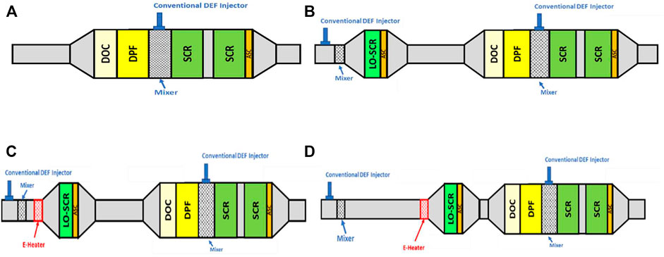
FIGURE 1. (A) Baseline 1 aftertreatment system schematic. (B) Baseline 2 aftertreatment system schematic with LO-SCR. (C) Aftertreatment system schematic with Close-Coupled (CC) LO-SCR and EH. (D) Aftertreatment system schematic with Underfloor (UF) LO-SCR and EH.
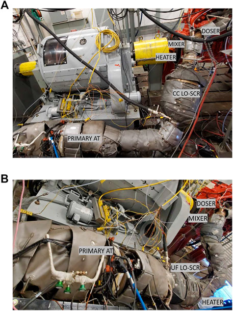
FIGURE 2. (A) Fully insulated aftertreatment system with CC LO-SCR and EH. (B) Fully insulated aftertreatment system with UF LO-SCR.
The test engine used for this program was a production 2018 model year Cummins X15 engine with a 500 hp production calibration similar to the engine utilized in the CARB Stage 3 on-road baseline testing (Sharp et al., 2021). The engine retained the production air handling system, Exhaust Gas Recirculation (EGR) system, internal components, and fuel system. The engine is as shown in Figure 3. The baseline aftertreatment system was representative of the catalysts in production for the 2022 model year which will be discussed later.
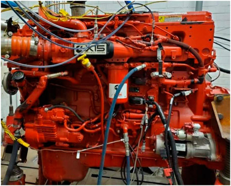
FIGURE 3. Cummins X15 engine platform installed in test cell.
During the 1990’s, EH concepts were explored to improve the cold start emissions (Reddy et al., 1994; Weiss et al., 1995; Hampton et al., 1996). These heaters were based on thin discs of a high temperature steel honeycomb. The resistance of the heater disc was adjusted to a target value by adding slits (in the element) to extend the electrical path length. The packaging of the heater disc used support rings or analogous structures, resulting in a self-supporting design, requiring no further axial support. Examples from the original work are shown in Figure 4.
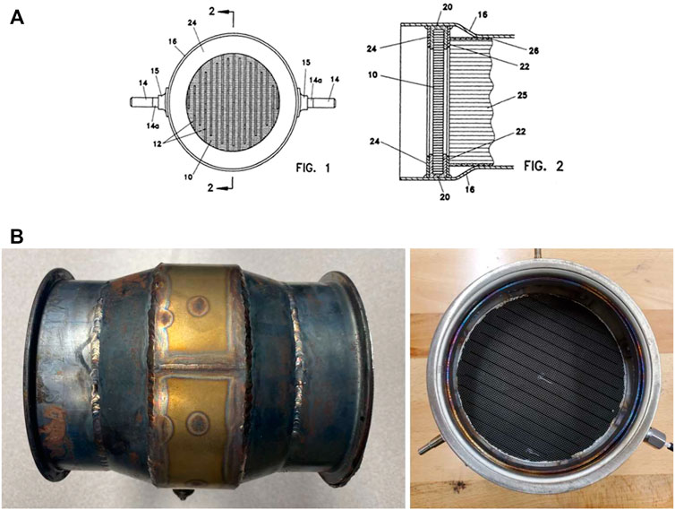
FIGURE 4. (A) Drawings of an electric catalyst heater (Anderson et al., 2021). Item 10 represents the heater disc, 22 and 24 the support rings, and 20 the insulation packaging material. (B) Image of the packaged heater.
An electrical potential (voltage) is applied during the “get hot” mode to the two electrodes resulting in an increase in heater body temperature through Joule heating. The industry is considering moving over to 48 V systems to power electric heaters and other accessories. In this work, a 48 V system to power a 7 kW EH results in a reasonable current limit of 145 amps. Much of the work in this paper had a maximum power setting of 5 kW which drops the maximum current to 105 amps. This is a reasonable current level for the time in which the EH is turned on.
Heater discs have cell densities of 300–450 Cells Per Square Inch (CPSI), which provide an excellent ratio of surface area for heat transfer to the gas and are 5–10 mm thick. The high efficiency and compact design make these honeycomb-based heater components very attractive. The product design is very flexible and allows design of the heater to any resistance, within the practically relevant range (currently ca. 200–500 mOhm).
The details of the catalyst heater used in this study can be found in Table 1. It should be noted that while it is possible to put a catalyst on the heater, the heater was not catalyzed in this work, so it heats the gas stream transferring the heat to the downstream catalyst components via convection. The heater can be considered in its simplest and cheapest form.
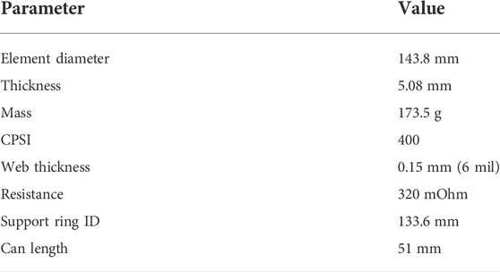
TABLE 1. Catalyst heater specifications.
The sample was packaged in the “Prototype” canning with the insulating material and support rings (Anderson et al., 2021), within a stand-alone can (no downstream catalyst directly attached), enabling placement within the exhaust pipe before the entrance cone to the LO-SCR. The setup had a bed thermocouple on the EH for monitoring purpose. The control algorithm utilized gas thermocouples for feedback temperature control which would be the intent for production applications.
The aftertreatment system has two distinct baselines. Baseline 1 is a primary aftertreatment system consisting of Diesel Oxidation Catalyst (DOC), Diesel Particulate Filter (DPF), compact mixer, Selective Catalytic Reduction (SCR) and Ammonia Slip Catalyst (ASC) and is representative of a 2022 model year. This system has a conventional a Diesel Exhaust Fluid (DEF) injector mounted on the mixer. Schematic representation of this system is shown in Figure 1A. Table 2 shows the catalyst volumes for this 2022 production like aftertreatment system.

TABLE 2. Baseline 1 system catalyst specifications.
Baseline 2 is a system that builds on Baseline 1 by adding a LO-SCR and another conventional DEF injector. There have been many relative studies that show the merit of adding a LO-SCR for cold start operation as this is a smaller catalyst that can heat up quickly when positioned closed to the engine. An illustration of the Baseline 2 aftertreatment system is shown in Figure 1B. There is a mixer located after the DEF injector.
Previous work (Sharp et al., 2021) utilized a heated doser in front of the LO-SCR. A heated doser allows DEF dosing down to 130°C exhaust temperature instead of the normal dosing temperature of 180°C for most advanced SCR systems. This study utilized a conventional doser (non heated) in front of the LO-SCR. With conventional dosing, the temperature required to begin dosing is 180°C to ensure proper DEF vaporization and prevention of urea deposits. However, later in this work, with the use of an EH, the LO-SCR temperature rises very fast so the use of a heated doser is considered not necessary. The difference between 130 and 180°C during a cold FTP is approximately a 5 s delay in dosing DEF. For reference, the same temperature difference at the downstream primary SCR is an 84 s delay and occurs much later in the cycle due to the thermal masses involved. The catalysts specifications, for Baseline 2 and EH tests are listed in Table 3, which includes the addition of an upstream LO-SCR catalyst system.
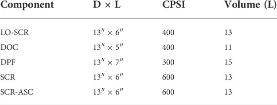
TABLE 3. Baseline 2 and EH testing catalyst specifications.
This program focuses on utilizing a LO-SCR and external heat supply upstream of the LO-SCR system shown in Table 3 as depicted by Figure 1C. The EH was placed ahead of the LO-SCR to enable NOx reduction as soon as possible. Heater control targeted the average gas temperature (inlet and outlet) of the LO-SCR.
There were two approaches to the LO-SCR aftertreatment configuration in this program that is relevant to packaging on a Class 8 Truck: 1) Close-Coupled (CC) LO-SCR and 2) Underfloor (UF) LO-SCR. The first approach was to represent a similar aftertreatment configuration as the Stage 3 Low NOx program (Sharp et al., 2021) and the second approach was to consider a real-world issue of packaging the LO-SCR on the chassis rail. As mentioned earlier, Figure 1B shows the baseline configuration of the LO-SCR. This setup is referred to as close-coupled, because the LO-SCR is as close to the turbine outlet as possible. This was kept constant in this study while the configuration of EH and LO-SCR was allowed to vary from in the close coupled and underfloor configurations. However, the distances are representative of placing the LO-SCR directly under the passenger steps.
The electric heater was similar in size to exhaust system and was easily integrated into the system. The mixer was located between the DEF doser and the electric heater. The illustration of the heater location is shown in Figure 1C. A photograph of the setup is shown in Figure 2A.
Exhaust insulation will likely be required to meet 2027 emissions regulations. Current one-box systems already reduce exhaust cooling and provide insulation. The work in this paper utilized exhaust blankets to retain heat similar to the Stage 3 work (Sharp et al., 2021). Limiting the cooling of the exhaust system will help to reduce power consumption of the EH or energy consumption of other heating strategies and should be considered for serial production.
The UF LO-SCR scenario was accomplished by moving the LO-SCR further away from the engine and closer to the DOC of the primary downstream system. A photograph of the setup is shown in Figure 2B. The EH stayed positioned in front of the LO-SCR while the doser and mixer remained close to the turbine exit. Hence, the only aftertreatment system that was moved was the EH and LO-SCR. An illustration of the system is shown in Figure 1D. A true UF LO-SCR configuration would be approximately six feet. In the test cell, the distance was longer to fully capture the appropriate worst-case distance. Hence, eight feet, as tested, would be an extreme length of UF configuration.
Table 4 provides the distances between the engine turbo out, LO-SCR and DOC for the different aftertreatment configurations. Baseline 1, which included only the primary AT system, was configured with 93 inches from the engine turbo out to the DOC. Baseline 2, which included the LO-SCR; configuration lengths are the same as the CC LO-SCR values.
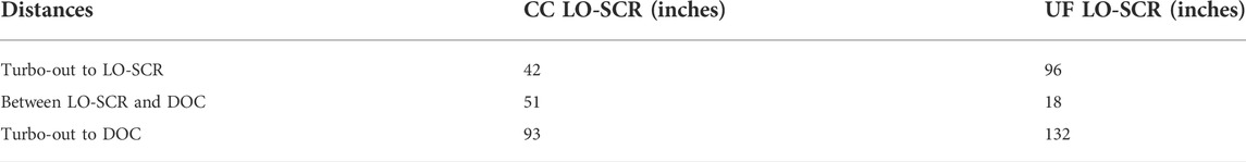
TABLE 4. Change in length for UF aftertreatment.
The aftertreatment system used in this work was hydrothermally aged by utilizing an accelerated aging protocol on a burner based aging platform. The aging protocol targeted the aftertreatment system with the equivalent amount of thermal exposure for a Full Useful Life (FUL) system i.e., 435,000 miles or 9,800 h of service accumulation time similar to previous works (Matheaus et al., 2021; McCarthy et al., 2022; Zavala et al., 2022). The catalysts at the end of this aging cycle are commonly referred to as “Development Aged” end of life catalysts. The difference between “Developed Aged” and “Real World Exposed to Chemical Poisoning” is characterized in previous works (Sharp et al., 2021).
A model-based controller (Sharp et al., 2017; Rao et al., 2020; Sharp et al., 2021) was being used in this program to control the DEF dosing similar to the baseline work (Meruva et al., 2022) and also the thermal management strategies to power on the EH. The model tracks ammonia storage in each of the SCR substrates and has a target ammonia storage based on temperature. The DEF doser configurations were the same between the tests with the EH and their respective baseline tests (Meruva et al., 2022). The model-based control is discussed in Meruva, et al. (Meruva et al., 2022).
The EH was powered up by an external power supply in the same way as previous work (Zavala et al., 2022) and similar to representative burner work (McCarthy et al., 2022). The control algorithm was Proportional Integral Derivative (PID) control as a basis and varied the voltage output of the power supply from 0 to 48 V. In this work, the feedback control for the PID was based on the average LO-SCR temperature. The average LO-SCR temperature was taken from the inlet and the outlet gas temperatures of the LO-SCR. These were production thermocouples that protrude 2 inches from the wall. This is consistent with other EH works in the past (Matheaus et al., 2021; Zavala et al., 2022). The voltage and current measurements were recorded at the EH and used to calculate the electrical power supplied to it. In real-time, a parasitic load was applied to the engine assuming an 80% generator efficiency. This is assuming a mild hybrid system with efficient power generation. Alternator efficiencies are known to be lower than 80%. The engine was not given credit for this parasitic load in the cycle work. However, CO2 and NOx emissions due to this additional load were included in the analysis. The formula used for the real-time addition of load is show in Eq. 1.
Emission testing in this work were performed on a motoring/absorbing engine dynamometer test cell utilizing raw exhaust measurements complying with a Code of Federal Regulations Part 1065. The measurement equipment used included the following:
• A raw Horiba MEXA 7000 series each for the engine out and TP emissions sampling
• An FTIR for LO-SCR out NOx emission measurements
The variability of NOx measurement is ∼ ± 0.001 g/hp-hr and CO2 measurement is ∼ ± 2 g/hp-hr. This is true for all the results discussed in this work.
Multiple key test cycles were evaluated using the engine and aftertreatments systems described above. These include the Heavy-Duty FTP and the LLC. Additional real world driving cycles evaluated were the Beverage Cycle and the Stay Hot Cycle. Finally, the European World Harmonized Transient Cycle (WHTC) was evaluated.
United States Environmental Protection Agency (US EPA) and CARB use the US Heavy-Duty FTP standard regulatory drive cycle for evaluation of emission standards. The regulatory FTP composite NOx limit for 2027 has been set to 0.02 g/hp-hr. Composite results are calculated as 6/7 of hot FTP and 1/7 cold FTP. This is a well-known cycle, so it is not shown here.
The LLC is a composite of multiple real-world driving cycles. Data was collected over various applications and combined to form this cycle. A problem with the FTP as an evaluation cycle is that it has higher loads than many real-world situations. Due to the higher-than-normal loads, the exhaust temperatures are much hotter, and the SCR system stays active. The LLC cycle was developed to be more realistic of use and has been approved as a regulatory cycle. These lighter loads force the exhaust temperatures to be much lower and NOx control becomes a challenge. The cycle is 5535 s in duration and is preceded by an FTP cycle with a 20-min soak period between them. The regulatory NOx limit for LLC cycle for 2027 has been set to 0.05 g/hp-hr.
The Beverage cycle is a subset of the LLC and is derived from a service truck delivering Beverages or packages. This cycle has idle sections that are longer than 1 min and several transient ramps. The average load is 7.1%. Four Beverage cycles (800 s each) are connected to form a test. The initial two cycles were for thermal conditioning. The emission values were quantified for the final two cycles only. The authors have found the Beverage cycle to be an excellent cycle for controls optimization as is much shorter (∼4 cycles in less than 1 h) than the LLC (∼1.5 h) while the load factors are nearly identical.
The Stay Hot drive cycle involves conditioning the engine and the aftertreatment system at a preset speed and load till the temperatures attain steady state. This is succeeded by a 40-min idle period before returning to the previous load and speed conditions. This cycle focuses on how a long idle impacts the NOx conversion efficiency of the aftertreatment system during the idle and immediately after a return to service.
The WHTC drive cycle is based on the global pattern of real heavy-duty commercial vehicle usage. It is a transient engine dynamometer cycle. The United Nations Economic Commission for Europe, Working Party on Pollution and Energy group developed the Global Technical Regulation group which covers a worldwide harmonized heavy-duty certification procedure for engine exhaust emissions. Composite WHTC values are calculated by 14% cold and 86% hot. This is also a well-known cycle, so it is not shown here. Typically, a European engine would be tested for the WHTC while for this work, a US production engine was tested for this cycle. As such, these results give an indication of what may be possible while no effort was spent to truly represent a European engine calibration.
The section shows the test results performance comparison of the CC LO-SCR and the UF LO-SCR configurations using different drive cycles which are FTP, LLC, Beverage, Stay Hot and the WHTC. These results demonstrate that using an EH with maximum power of 7 kW upstream of a LO-SCR in combination with a production engine and an aftertreatment system representative of 2022 production will be able to achieve NOx standards for the MY 2027.
This project used two baseline aftertreatment systems. The baseline 1 was to represent the current 2022 production aftertreatment system while baseline 2 added the upstream LO-SCR to baseline 1 configuration. Baseline 2 is important for this work as the LO-SCR was used with all the EH results.
Baseline 1 (shown in Figure 1A) emissions are shown in Table 5. Please note that the SCR is larger than what would be in production for this engine and model year. Therefore, these emissions are better than what a 2018 engine + aftertreatment system would yield. The FTP composite Brake Specific NOx (BSNOx) value is 6.5 times higher than the limit of 0.02 g/hp-hr. For the LLC, the baseline 1 value is 18 times the limit of 0.05 g/hp-hr. Even with the larger aftertreatment system, additional technology is required to reduce NOx emissions, primarily at lighter loads.
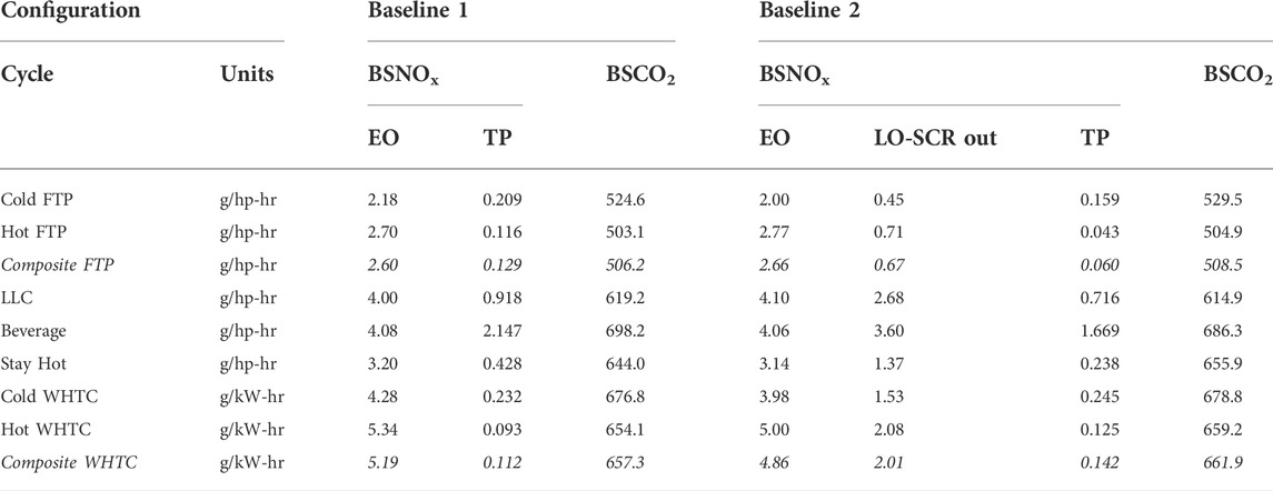
TABLE 5. Baseline 1 and Baseline 2 emission test results
The baseline 2 (shown in Figure 1B) test results for both the above-mentioned configurations are the same as our previous works for a non-CDA engine with a conventional DEF doser (unheated DEF) for the LO-SCR (Meruva et al., 2022) and the summary of those results are as shown in Table 5. The composite FTP NOx value is three times the limit. The LLC value is more than 14 times the limit. The baseline is also not within the EURO VI regulations of 0.46 g/kW-hr for the composite WHTC. Just adding a LO-SCR does not immediately remedy the high NOx values. Engine calibration/optimization would improve on these values. However, additional technologies are still required to meet 2027 emissions standards.
Table 6 shows the FTP composite values of both the CC LO-SCR (shown in Figure 1C) and the UF LO-SCR (shown in Figure 1D) configurations, with the EH upstream of the LO-SCR, as these are compared to both baseline results. The CC configuration is within the NOx regulatory limit of 0.02 g/hp-hr for the year 2027. The UF configuration exceeds the limit; however, the UF configuration was tested without any changes to the calibration and the authors believe that tuning the model will reduce the TP NOx values. This is still a significant finding as there is considerable additional distance and metal surface area. Both the EH configurations had a NOx conversion efficiency of over 99%. Observing the LO-SCR NOx out values, the LO-SCR reduced 75% of the EO NOx for Baseline 2. The LO-SCR reduced 84% of the EO NOx in the CC configuration. Finally, in the UF configuration, the LO-SCR reduced 87% of the EO NOx. With this said, the LO-SCR is not specifically designed to handle all the engine out NOx. There is room to optimize LO-SCR size.

TABLE 6. FTP composite, cold FTP, and hot FTP test results
The composite results in Table 6 are shown graphically in Figure 5. As observed in Table 6, UF LO-SCR seems to slightly better NOx conversion than the CC LO-SCR as the UF LO-SCR is closer to the downstream aftertreatment system which helps in preserving thermal inertia of the catalyst, which is lower in the case of a CC LO-SCR. The EH cases reduce TP NOx significantly with a modest penalty in CO2. The heater control strategy for FTP was the same between both the configurations with a maximum power consumption of 7 kW and the average LO-SCR target gas temperature of 235°C (average LO-SCR T = (Tin+Tout)/2). The control temperature on the LO-SCR was 10°C higher than the optimal value found in (Zavala et al., 2022); however, it is good to see that the values are very close between 225 and 235°C.
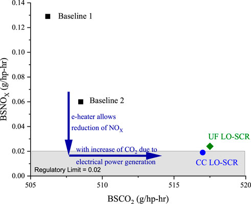
FIGURE 5. BSCO2 and BSNOx shown for composite FTP for all configurations.
The cold FTP results are shown in Table 6. The CC configuration provided the lowest TP NOx emissions with only 0.67 kW-hr of electrical energy used. The UF configuration required 0.79 kW-hr of energy and had higher TP NOx emissions than the CC variant. Ideally, the cold FTP NOx emissions target is 0.08 g/hp-hr to have enough margin for the composite calculation. Increasing the distance of the aftertreatment system from the engine inherently allows the exhaust to cool down further so increased heater power is expected. Also, the UF configuration may benefit from a different heater control logic to reduce TP NOx.
Requiring the engine to generate the power for the EH shows up in higher CO2 numbers. Naturally, the higher electrical consumption yields higher CO2. Less than 1 kW-hr of energy is required to reduce the cold TP NOx emissions in the range to meet 2027 emissions limits. The energy is spent during the first 600 s of the FTP.
Figure 6 shows a graphical comparison of the CC LO-SCR and the UF LO-SCR configurations to Baseline 2 for the cold FTP cycle. The heater is required for the first half of the FTP because this is the lighter loaded portion. After 600 s, the engine generates enough heat to keep the SCR in an optimum temperature range.
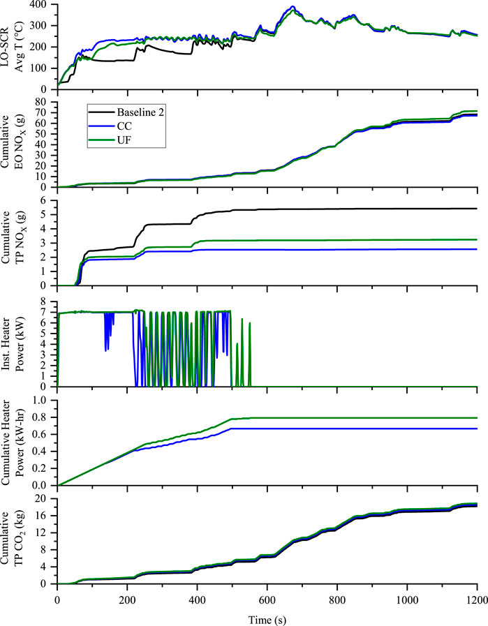
FIGURE 6. Comparison of the CC LO-SCR and UF LO-SCR to Baseline 2 on a Cold FTP cycle for the LO-SCR average temperature, emissions, and heater electrical power consumption.
Observing the LO-SCR average temperature, the EH does a great job of raising the exhaust temperature above 200°C by 105 s for the CC, and 138 s for the UF. A large portion of the NOx emissions is emitted during the first acceleration (∼45 s). This can be seen in the cumulative TP NOx graph. Since the CC system reaches more optimum temperature faster, it can start reducing NOx on the first acceleration. The UF does not reach temperature as quickly, so it matches Baseline 2 for the first acceleration. At the second accelerations (218 s), both CC and UF are reducing a large portion of the NOx emissions. Baseline 2 is still below optimum temperature. By the third acceleration (382 s), both CC and UF configurations are effectively reducing NOx.
At approximately 200 s, the heater control logic on the CC configuration starts to reduce power. This can be observed on the instantaneous heater power graph as it starts to pulse. For the UF configuration, the heater stays at maximum power for a longer period. The impact on electrical consumption is shown on the cumulative heater power graph.
Table 6 shows the numerical comparison of both the configurations along with the baselines for the hot FTP cycle. There are some variations in EO NOx due to test-to-test variation. The engine is expected to operate on two different modes; assumed as thermal management mode and fuel economy mode. The engine switches between these modes based on the aftertreatment temperature. In the case of the UF configuration, as the aftertreatment system temperature is slightly higher than other configurations the engine is expected to stay on fuel economy mode for a longer duration which is expected to be the cause of a higher EO NOx. Both EH configurations reduce TP BSNOx to levels appropriate to meet 2027 emissions.
The EH BSCO2 values are 1.4% higher than baseline values because the engine is required to generate the electricity consumed by the EH. This is not a fair comparison because if the baseline engine was calibrated in a manner to meet 2027 emissions standards, the BSCO2 will likely be higher than reported here. One such technique, retarding injection timing, is known to increase fuel consumption and CO2 emissions.
A graphical comparison of the CC and UF configurations to the baselines are shown in Figure 7. Since the hot FTP follows the cold FTP with a 20-min soak, there is enough thermal heat retained in the substrates that the NOx generated in the first acceleration is reduced in all configurations. The LO-SCR substrate cools down during the idle portions of the FTP. This shows up as increased TP NOx emission for the second and third accelerations on the cumulative TP NOx graph. The EH configurations have NOx fully under control by the third acceleration. The EH controller in both configurations start reducing power early in the cycle. The integrated electrical consumption is 0.40 and 0.48 kW-hr for the CC and UF, respectively. The hot FTP uses 40% less electrical power than the cold FTP, irrespective of the configuration.
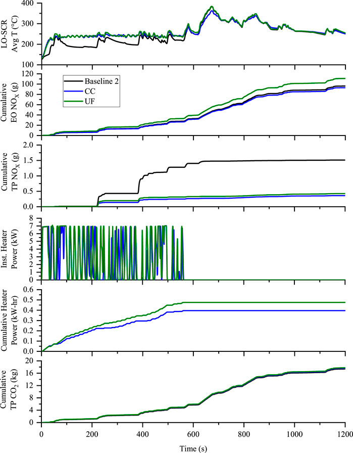
FIGURE 7. Comparison of the CC LO-SCR and UF LO-SCR to Baseline 2 on a Hot FTP cycle for the LO-SCR average temperature, emissions, and heater electrical power consumption.
Results for the LLC cycle are shown Table 7. The EO NOx emissions are higher for the heater configurations indicating that the engine was operating in a more fuel-efficient mode. Aftertreatment temperatures are the primary basis for determining the mode of operation. The engine is allowed to operate more efficiently when the aftertreatment system is hot.

TABLE 7. LLC test results.
The heater control strategy for the LLC cycle was set to target 225°C as the average LO-SCR temperature with 5 kW max heater power. Electrical energy consumption is much greater for the LLC than seen on the FTP tests. The LLC is 1.5 h long compared to the 20-min FTP. Overall lower loaded cycle with a longer test duration yields an increased electrical demand which directly increases CO2. The UF configuration had a lower TP NOx but a higher electrical energy consumption than the CC configuration.
The cycle results for the LLC are graphically shown in Figure 8. The NOx regulatory limit for this cycle is 0.05 g/hp-hr. The dramatic reduction in BSNOx is apparent when utilizing the EH. Also apparent is the increase in BSCO2. However, the baseline CO2 numbers are at a much higher NOx value. The actual CO2 numbers for a non-EH 2027 solution is not known at this time. It can be assumed that NOx reduction comes at a cost of CO2 unless a technology such as CDA is utilized.
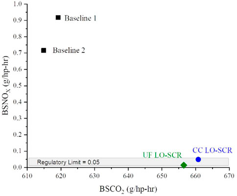
FIGURE 8. Cycle results for the LLC.
The comparison graph for the LLC is provided in Figure 9. The LO-SCR average temperature for both EH cases is considerably higher than Baseline 2, which accounts for the excellent NOx reduction (see cumulative TP NOx graph). Both configurations had an increased average temperature of 52°C when compared to Baseline 2. Both configurations operated with the same heater strategy which was 5 kW maximum heater power and an average LO-SCR setpoint of 225°C. The UF configuration consumed 14% more power than the CC configuration, mostly on the first half of the cycle.
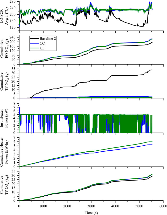
FIGURE 9. Comparison of the CC LO-SCR and UF LO-SCR to Baseline 2 on the LLC cycle for the LO-SCR average temperature, emissions, and heater electrical power consumption.
Table 8 shows the numerical comparison of both the configurations along with the baselines for the Beverage cycle. This is a good “in-use” evaluation of delivery trucks such as UPS, Coca-Cola, and Amazon. This is also a good representation of highly congested traffic areas such as Brazil. Both EH cases show over 99% NOx conversion efficiency with similar heater power consumption. On average, the EH cases had 11% higher CO2 than the baseline cases.
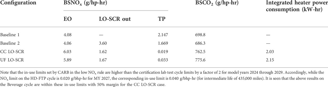
TABLE 8. Beverage cycle test results.
Figure 10 shows the graphical comparison for the Beverage cycle. The heater control strategy was the same as the LLC cycle: 225°C average LO-SCR target with 5 kW max heater power. The average LO-SCR for Baseline 2 over the cycle was 163°C. This still allowed for a 59% NOx conversion efficiency due to ammonia storage. However, additional NOx control is required to meet emissions requirements. The EH in the CC configuration had an average temperature increase of 54°C. The EH in the UF configuration had an average temperature increase of 52°C. The cumulative heater power values are nearly identical for the two cases, slightly over 2 kW-hr.
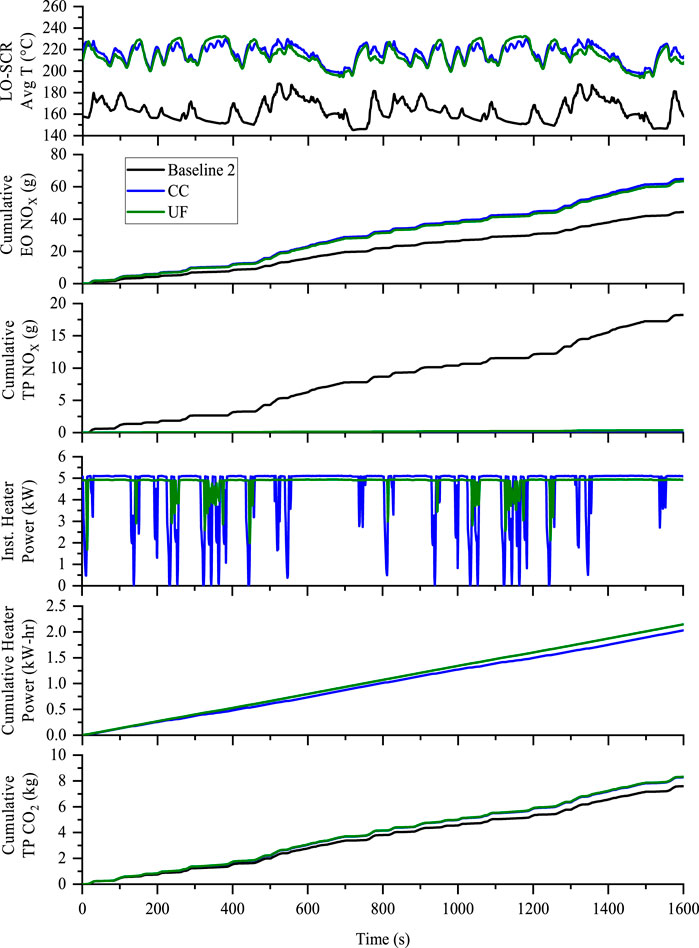
FIGURE 10. Comparison of the CC LO-SCR and UF LO-SCR to Baseline 2 on the Beverage cycle for the LO-SCR average temperature, emissions, and heater electrical power consumption.
The Stay Hot test results are shown in Table 9. Both EH cases show a 99% NOx conversion efficiency. Similar TP NOx are achieved between the two cases with similar heater power consumed. These emissions are within the 2027 in use standards.
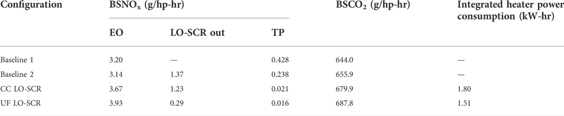
TABLE 9. Stay Hot test results.
Multiple heater strategies were tested, and the best NOx/CO2 tradeoffs are presented in this paper. For the CC LO-SCR, the best strategy was a maximum heater power of 5 kW and a single setpoint of 225°C targeting the average LO-SCR temperature. The heater strategy for the UF LO-SCR configuration is different and is shown in Table 10. Since the UF configuration is much closer to the primary AT system, the most efficient strategy tried used the primary SCR inlet temperature as feedback. Since these are closer together, the EH also impacts the primary SCR temperature.
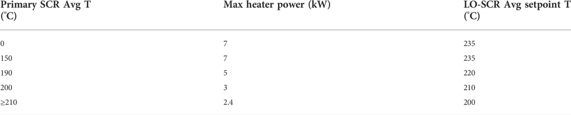
TABLE 10. Multi-tier heater control strategy based on downstream SCR temperature.
The multi-tier thought process is to minimize the electrical power needed. One way to minimize fuel consumption and CO2 increase is to limit the maximum heater power. In some cases, however, the limited power does not allow for enough heat generation and there is NOx break through. The multi-tier strategy was developed so that when the target catalyst is colder, then a higher maximum electrical power and a higher setpoint temperature is allowed. As the target catalyst increases in temperature, the maximum power allowed and the setpoint temperature are reduced to minimize the electrical power consumption and thereby minimizing CO2. The multi-tier approach was applied in different ways by targeting different catalyst temperatures.
The graphical comparison for the Stay Hot tests is provided in Figure 11. The EH for the CC case turns on 239 s after drop to idle. The EH turns on for the UF case at 388 s after drop to idle. For the UF case, the strategy is limiting maximum EH power due to the temperature of the primary SCR. At 1250 s, the primary SCR is cooling off and the maximum heater power is increased slowly over time. There is a difference in average LO-SCR temperature during the maximum power limited period (800–1250 s). Afterward, the average LO-SCR temperatures converge. The benefit of the multi-tier strategy shows up as a reduced cumulative integrated power. Observing the cumulative TP NOx graph, Baseline 2 starts to have NOx breakthrough at 2000 s. As the engine returns to service, there is a spike in TP NOx. Both EH cases keep the NOx breakthrough at a minimum.
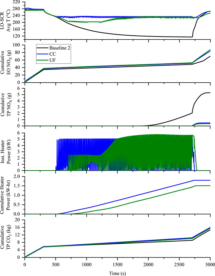
FIGURE 11. Comparison of the CC LO-SCR and UF LO-SCR to Baseline 2 on the Stay Hot cycle for the LO-SCR average temperature, emissions, and heater electrical power consumption.
The composite WHTC results are shown in Table 11. The baseline cases show a 97% NOx reduction. The WHTC is a high enough loaded cycle that the baseline configurations do well. The EH cases have over 99% NOx reduction. The increase in BSCO2 is minimal because the electrical power required is small. The EH control algorithm for all WHTC cases were targeting the LO-SCR average temperature to be 235°C and allowing the full 7 kW heater power, if needed.
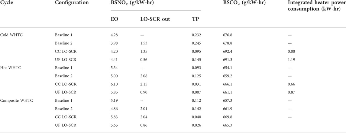
TABLE 11. Composite WHTC, cold WHTC and hot WHTC test results.
The cold WHTC results are shown in Table 11. The NOx conversion efficiencies for the baseline cases are in the low 90% range. The EH allows for higher NOx conversion efficiencies (97%). The increase in CO2 is 2% on average.
The graphical comparison for the cold WHTC is provided in Figure 12. The idle periods for the WHTC are roughly 200–360 s, 710–775 s, and 1150–1200 s. The EH is on from the start of the cycle to 650 s and from 1000 to 1200 s. It is not utilized much in other areas of the cycle. For the EH cases, most of the TP NOx is generated in the first 100 s.
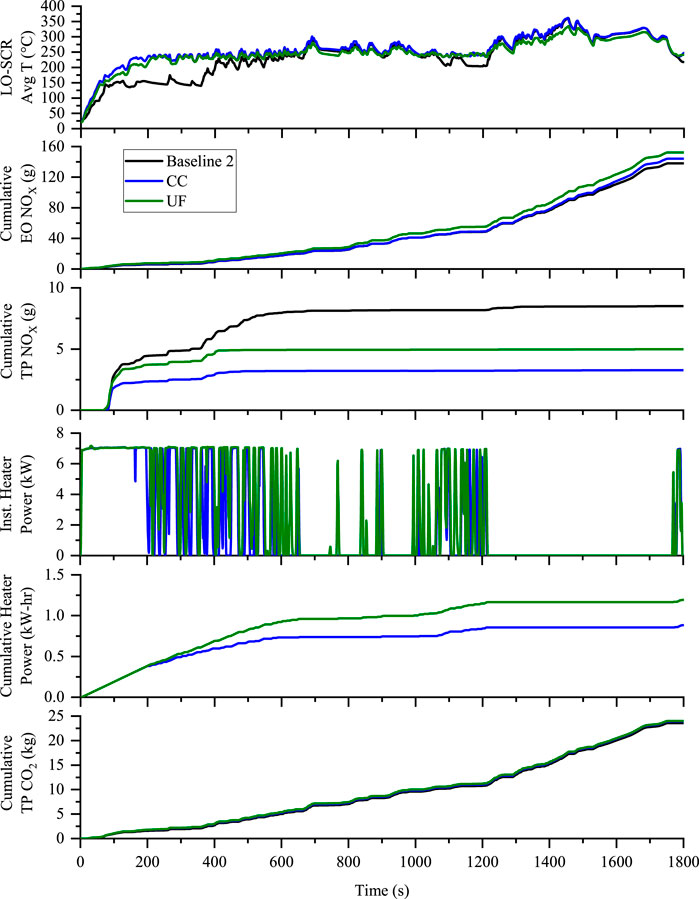
FIGURE 12. Comparison of the CC LO-SCR and UF LO-SCR to Baseline 2 on the cold WHTC for the LO-SCR average temperature, emissions, and heater electrical power consumption.
The hot WHTC results are shown in Table 11. The hot test uses 25% less electrical energy than the cold test. The EH cases cut TP NOx by more than 60% when compared to baseline. The results are shown graphically in Figure 13. The EH controller maintains the average LO-SCR at or above 235°C. For the EH cases, the cumulative TP NOx is under 1 g. As before, the UF configuration used more electrical energy than the CC configuration.
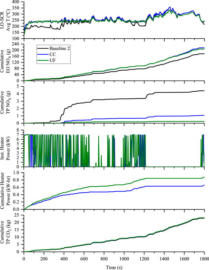
FIGURE 13. Comparison of the CC LO-SCR and UF LO-SCR to Baseline 2 on the hot WHTC for the LO-SCR average temperature, emissions, and heater electrical power consumption.
The test results from this program show that the CARB proposed 0.02g/hp-hr NOx target for the year 2027 can be achieved with a current production engine without any modifications to it. The following conclusions can be made from the above test data:
• A small EH coupled with a LO-SCR and downstream primary aftertreatment system can reduce the TP NOx emissions and reach an FTP composite of 0.02 g/hp-hr while also maintaining the NOx emissions within 0.05 g/hp-hr for an LLC cycle. A composite FTP NOx of 0.019 g/hp-hr was achieved with hydrothermal end-of-life aged catalysts. Using the same catalysts, TP NOx of 0.049 g/hp-hr for the close coupled configuration and 0.014 g/hp-hr NOx for the underfloor configuration was achieved for the LLC. The CC LO-SCR has an added benefit of being close to the engine which yields higher temperature for the catalyst helping in reducing the heater power required to be generated to keep the aftertreatment at the required temperature
• Considering that there are packing difficulties for the CC LO-SCR, even the UF LO-SCR that is positioned further downstream can help in achieving the 2027 NOx emissions with a minimal additional fuel penalty
A summary of all TP NOx and CO2 results is shown in Table 12 that includes the FTP, LLC, Beverage, Stay Hot and WHTC with the LO-SCR in both the close coupled (CC) and underfloor (UF) configurations. The test data results prove that an EH with a maximum power capacity of 7 kW should a good viable option in reducing the NOx emissions and its maximum power capacity might be required only on few tests, especially during the cold starts but most of the hot cycles might just need a maximum power capacity of 5 kW.
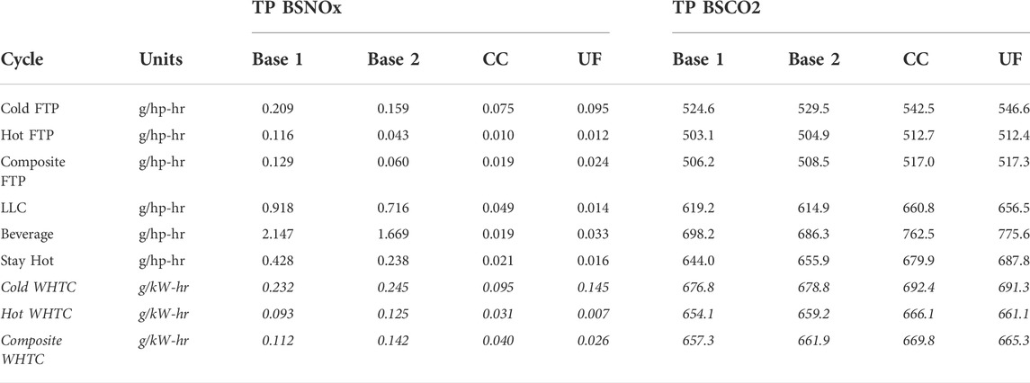
TABLE 12. Summary TP BSNOx and TP BSCO2 test results.
CDA technology seems to be a viable option to increase the fuel economy and improve the aftertreatment thermal management as observed in previous works (Joshi et al., 2017; McCarthy, 2017; Ramesh et al., 2018; McCarthy, 2019). Future work could include adding CDA technology to the engine in combination with the EH technology to provide a better NOx vs. CO2 trade off. This future work is planned as a follow-up to previous work (Matheaus et al., 2021) using a smaller diameter EH in front of the LO-SCR while removing the heated DEF injector in front of the LO-SCR. The authors believe that adding the EH in this location will allow a standard, unheated DEF doser, to be used.
The original contributions presented in the study are included in the article/Supplementary Material, further inquiries can be directed to the corresponding author.
All authors participated in developing the test plan and the outline of the paper. JM wrote abstract, introduction, and summary. TC and AJ wrote section about the EH. PM and AM conducted the testing and wrote about the test results, including the analysis. All authors participated in editing the final draft and adding additional information to tell the story.
The authors would like to acknowledge the support of Eaton, Corning and SwRI in this work.
Author JM was employed by Eaton (United States). Authors TC and AJ were employed by Corning Inc.
The remaining authors declare that the research was conducted in the absence of any commercial or financial relationships that could be construed as a potential conflict of interest.
All claims expressed in this article are solely those of the authors and do not necessarily represent those of their affiliated organizations, or those of the publisher, the editors and the reviewers. Any product that may be evaluated in this article, or claim that may be made by its manufacturer, is not guaranteed or endorsed by the publisher.
Anderson, J. G., Collins, T. A., and Hampton, L. E. (2021). Axially assembled enclosure for electrical fluid heater having a peripheral compression ring producing a diametrically balanced force. Alexandria, VA: US patent office.
Berndt, C. (2019). An experimental study of A passive nox adsorber (pna) for the reduction of cold start diesel emissions. Houghton, Michigan: Michigan Technological University. Open Access Master's Thesis.
Brin, J., Keim, J., Christensen, E., and Holman, R. (2021). Applying a driven turbocharger with turbine bypass to improve aftertreatment warm-up and diesel nitrous oxides conversion. SAE Int. J. Commer. Veh. 14 (3), 391–407. doi:10.4271/02-14-03-0032
California Air Resources Board (2020). California adopts strong new regulation to further reduce smog-forming pollution from heavy-duty diesel trucks. Available at: https://ww2.arb.ca.gov/news/californiaadopts-strong-new-regulation-further-reduce-smog-formingpollution-heavy-duty.
California Air Resources Board (2019). Greenhouse gas standards for medium- and heavy-duty engines and vehicles. Available at: https://ww2.arb.ca.gov/our-work/programs/ghg-std-md-hd-eng-veh/about.
Hampton, L. E., Buhrmaster, C. L., and Thompson, D. F. (1996). Durability of advanced electrically heated catalyst design. United States: SAE International. doi:10.4271/960345
Harris, T., McCarthy, J., Sharp, C., Zavala, B., and Matheaus, A. (2021). Meeting future NOx emissions limits with improved total fuel efficiency. Rostock, Germany: Heavy-Duty, On- and Off-Highway Engines.
Heavy-Duty Warranty Cost Study Report (2019). California air Resources board staff current assessment of the technical feasibility of lower NOX standards and associated test procedures for 2022 and subsequent model year medium-duty and heavy-duty diesel engines. Available at: https://ww3.arb.ca.gov/msprog/hdlownox/white_paper_04182019a.pdf.
Joshi, M. C., Gosala, D. B., Allen, C. M., Vos, K., Van Voorhis, M., Taylor, A., et al. (2017). Reducing diesel engine drive cycle fuel consumption through use of cylinder deactivation to maintain aftertreatment component temperature during idle and low load operating conditions. Front. Mech. Eng. 8, 1. doi:10.3389/fmech.2017.00008
Kasab, J., de Monte, M., Hadl, K., Noll, H., Mannsberger, S., Graf, G., et al. (2021). Using close-coupled SCR to meet ultra-low NOx requirements. Available at: https://cleers.org/wp-content/uploads/formidable/3/2019CLEERS_Kasab_Web.pdf.
Kasab, J. J., Hadl, K., Raser, B., Sacher, T., and Graf, G. (2021). Close-coupled SCR - an approach to meet ultra-low NOx requirements for heavy-duty diesel engines. Ann Arbor, Michigan: CLEERS Virtual Workshop.
Matheaus, A., Neely, G., Sharp, C., Hopkins, J., and McCarthy, J. E. (2021). Fast diesel aftertreatment heat-up using CDA and an electrical heater. SAE Technical Paper 2021-01-0211. doi:10.4271/2021-01-0211
McCarthy, J. E. (2019). Simultaneous CO2 and NOX reduction for medium & heavy-duty diesel engines using cylinder deactivation. Brazil: Sao Paulo.
McCarthy, J. (2017). Cylinder deactivation improves diesel aftertreatment and fuel economy for commercial vehicles. Stuttgart, Germany: 17th Stuttgart International Symposium.
McCarthy, J., Matheaus, A., Zavala, B., and Sharp, C. (2022). Meeting future NOX emissions over various cycles using a fuel burner and conventional aftertreatment system. Detroit, Michigan: SAE Technical Paper 2022-01-0539. doi:10.4271/2022-01-0539
Meruva, P., Matheaus, A., Zavala, B., Sharp, C., and McCarthy, J. (2022). Model based controller for advanced aftertreatment. SAE International Journal of Commercial Vehicles.
Milovanovic, N., Hamalian, S., Lewander, M., and Larson, K. (2016). The novel SCR and PNA exhaust gas after treatment systems for diesel passenger cars. Springer. doi:10.1007/978-3-658-13255-2_4
Ramesh, A. K., Gosala, D. B., Allen, C. M., Joshi, M. C., Shaver, G. M., McCarthy, J., et al. (2018). Cylinder deactivation for increased engine efficiency and aftertreatment thermal management in diesel engines. United States: SAE International.
Rao, S., Sarlashkar, J., Rengarajan, S., Sharp, C., and Neely, G. (2020). A Controls Overview on Achieving Ultra-Low NOx. SAE Technical Paper 2020-01-1404. doi:10.4271/2020-01-1404
Reddy, K. P., Gulati, S. T., and LambertWeiss, D. (1994). High temperature durability of electrically heated extruded metal support. SAE Technical Paper 940782.
Scott Sluder, C., Storey, J., Lewis, S., and Lewis, L. (2005). Low temperature urea decomposition and SCR performance. SAE Technical Paper 2005-01-1858. doi:10.4271/2005-01-1858
Sharp, C., Neely, G., Zavala, B., and Rao, S. (2021). CARB low NOX stage 3 program-final results and summary. SAE Int. J. Adv. & Curr. Prac. in Mobility 3 (4), 1508–1525. doi:10.4271/2021-01-0589
Sharp, C., Webb, C., Neely, G., Sarlashkar, J., Rengarajan, S. B., Yoon, S., et al. (2017). Achieving ultra low NOX emissions levels with a 2017 heavy-duty on-highway TC diesel engine and an advanced technology emissions system - NOX management strategies. SAE Int. J. Engines 10 (4), 1736–1748. doi:10.4271/2017-01-0958
Webb, C., Stephenson, P., Meijer, M., and Coumans, A. (2021). Future regulatory technology options to reduce risk in application for heavy-duty diesel engines. Aachen, Germany: Aachen Colloquium Sustainable Mobility.
Weiss, D. S., Buhrmaster, C. L., Hampton, L. E., Powell, W., and Socha, L. S. (1995). Durability of extruded electrically heated catalysts. SAE Technical Paper 950404. doi:10.4271/950404
Zavala, B., McCarthy, J., Matheaus, A., and Sharp, C. (2022). Fast diesel aftertreatment heat-up using CDA and an electrical heater between 1.2 and 5.0 kW. Frontiers in Mechanical Engineering.
Keywords: electric heater, advanced aftertreatment, light off SCR, heavy-duty emissions, reduced NOx, FTP, light load cycle, WHTC
Citation: Meruva P, Matheaus A, Sharp CA, McCarthy JE, Collins TA and Joshi A (2022) Meeting future NOX emissions using an electric heater in an advanced aftertreatment system. Front. Mech. Eng 8:979771. doi: 10.3389/fmech.2022.979771
Received: 27 June 2022; Accepted: 03 August 2022;
Published: 06 September 2022.
Edited by:
Jinlong Liu, Zhejiang University, ChinaReviewed by:
Yan Yuchao, Zhejiang University, ChinaCopyright © 2022 Meruva, Matheaus, Sharp, McCarthy, Collins and Joshi. This is an open-access article distributed under the terms of the Creative Commons Attribution License (CC BY). The use, distribution or reproduction in other forums is permitted, provided the original author(s) and the copyright owner(s) are credited and that the original publication in this journal is cited, in accordance with accepted academic practice. No use, distribution or reproduction is permitted which does not comply with these terms.
*Correspondence: Andrew Matheaus, YW5kcmV3Lm1hdGhlYXVzQHN3cmkub3Jn
Disclaimer: All claims expressed in this article are solely those of the authors and do not necessarily represent those of their affiliated organizations, or those of the publisher, the editors and the reviewers. Any product that may be evaluated in this article or claim that may be made by its manufacturer is not guaranteed or endorsed by the publisher.
Research integrity at Frontiers
Learn more about the work of our research integrity team to safeguard the quality of each article we publish.