- 1Department of Civil Engineering, Faculty of Engineering, Lishui University, Lishui, China
- 2Lishui Science and Technology Innovation Service Center, Lishui, China
- 3School of Civil Engineering, Tianjin University, Tianjin, China
- 4China Academy of Building Research, Beijing Glory PKPM Technology Company Limited, Beijing, China
The wooden arch corridor bridge is a typical representative of Chinese wooden bridges, holding significant historical research value. Currently, these bridges face issues of severe component deformation and insufficient load-bearing capacity. To address these problems, this study employs CFRP reinforcement on the components of wooden arch corridor bridges to reduce deformation and enhance load-bearing capacity. Experimental research on CFRP reinforcement has yielded the elastic modulus of the bonding interface. Given the lack of an accurate numerical model for wooden arch corridor bridges, this study establishes a precise numerical model by setting parameters based on load test data from wooden arch corridor bridges. The elastic modulus obtained from the experiments is input into the numerical model for analysis. The results indicate that CFRP exhibits excellent reinforcement performance, with the load-bearing capacity of the reinforced damaged components still reaching 75%–85% of their original capacity, while the load-bearing capacity of the reinforced undamaged components increases to 130%–140% of their original capacity. The failure modes of the CFRP-reinforced wooden components suggest that allowing for some gaps in the bonding of CFRP can enhance overall ductility. The application of CFRP to wooden arch corridor bridges also demonstrates favorable reinforcement effects, increasing the load-bearing capacity of the arch surface by approximately 20%, thereby providing a theoretical basis for the reinforcement of wooden arch bridge frameworks.
1 Introduction
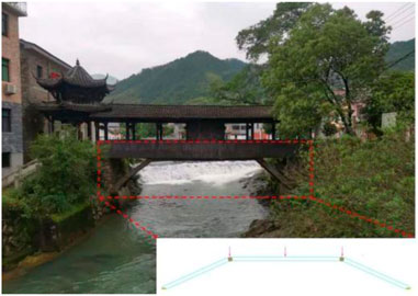
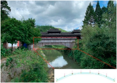
The wooden arch bridge is a quintessential example of timber bridges, characterized by its interlocking mortise and tenon woven arch structure. This structure primarily consists of the “Sanjiao Miao” (three-section sprout), “Wujiao Miao” (five-section sprout), and “Niu Tou” (ox head). The main load-bearing capacity is found in the “Sanjiao Miao,” which combines the side sprouts of the three or five-section sprouts with the central flat sprout. Currently, wooden arch bridges can be classified into two styles: “Sanjiao Miao” and “Sanjiao” or “Wujiao Miao.” For instance, the “Sanjiao Miao” style is exemplified by Puji Bridge, located in Fucun Natural Village, Hejin Prefecture, Xiandu Township, Liandu District. This bridge was constructed in the 17th year of the Republic of China (1928 AD) and has a total length of 22.1 m, a width of 3.2 m, a clear span of 13.7 m, and a height of 5.00 m. In contrast, the “Wujiao Miao” style is represented by Long Bridge, situated in Yueshan Village, Jushui Township, Qingyuan County, Zhejiang Province. Constructed in the fifth year of Ming Rixing (1625 AD), it features a total length of 28.2 m, an arch span of 14.1 m, a clear span of 19.5 m, and a width of 6 m. Both Puji Bridge and Long Bridge fully preserve the architectural styles of “Sanjiao Miao” and “Sanjiao” or “Wujiao Miao” wooden arch bridges. They serve as important references for the study of ancient bridge history in China and possess significant historical, artistic, and scientific value.
The existing wooden arch bridges have a long history and are often classified as national treasures due to their cultural significance. Overall, these bridges are well-preserved; however, some local components have experienced a noticeable reduction in load-bearing capacity, attributed to various material choices made during construction or surface corrosion caused by moisture. Furthermore, increased bridge loads during the flood season, aimed at preventing scouring and accommodating the high volume of tourists during peak seasons, can lead to significant deformation of components or insufficient load-bearing capacity, resulting in the bridge tilting to one side. Therefore, reinforcing the original components of the wooden arch bridge in situ to maintain its original appearance is of great importance.
From Figures 1, 2, it is evident that the main load-bearing points of the components of the wooden arch bridge are in the middle section of the central components. The existing wooden arch bridge components, mostly the central components, suffer from insufficient load-bearing capacity. Currently, there is no satisfactory solution for reinforcing the central components of the wooden arch bridge. Typically, the central components are either completely replaced after being dismantled from the frame or partially removed and connected to the pier platform, followed by reinforcement using nails, steel plates, and rivets. This approach is costly and demands high construction technology requirements. Additionally, nails and steel plates are used to strengthen the mortise and tenon connections. Many studies have shown that this method can enhance their load-bearing capacity to some extent (Jin et al., 2022; Wang et al., 2021; Guo et al., 2020; Zhou et al., 2016; Xue et al., 2015). However, it has a short aging time, is prone to corrosion and detachment, leading to a significant decline in reinforcement effectiveness.
Currently, there is an urgent need for a new reinforcement scheme for the central components of wooden arch bridges. Li et al. (2019) analyzed and prospected the restoration and reinforcement techniques of Chinese ancient wooden structures. They suggested that, based on inheriting and exploring traditional techniques, there should be active introduction of new materials and technologies to compensate for traditional deficiencies. There have been some studies on the application of CFRP in glued laminated timber beams. Klaudia et al. (2021) found that the failure mode of CFRP-reinforced glued laminated timber beams has changed. İşleyen et al. (2021) and Vahedian et al. (2019) demonstrated that CFRP applied to composite timber beams can improve their ultimate load-carrying capacity. Siha et al. (Zhou et al., 2020; A et al., 2021) investigated CFRP and near-surface reinforcement of circular wooden columns, showing improved axial load-carrying capacity and good deformation coordination for all three materials. Ghanbari Ghazijahani et al. (Tohid et al., 2020) enhanced the load-carrying capacity and ductility of CFRP-reinforced I-beams. Brol and Agnieszka (2019) and Bashandy et al. (2018) used various composite materials to reinforce aged wood, with CFRP showing the best reinforcement effect. CFRP reinforcement also has a good effect on defective or extended wooden beams (Rescalvo et al., 2018a; Rescalvo et al., 2018b; Zhang et al., 2018; Yuan et al., 2014; Zhu et al., 2005; Lin et al., 2016). Buell and Saadatmanesh (2005) applied composite materials in the form of fabric wrapping or laminates to enhance the load-bearing capacity of wooden bridges, and the results indicated that the carbon fiber fabric significantly improved the bending and shear strength of the wooden beams. Gentile et al. (2000) utilized CFRP for the reinforcement of wooden bridges, studying its bending capacity, and found that the bending strength increased by 18%–46%. Dagher and Lindyberg (2004) bonded FRP to the tension side of wooden bridges, repairing and upgrading existing wooden structures, and their results demonstrated good reinforcement performance. Qiu et al. (2021) applied three different CFRP reinforcement methods to laminated bamboo arches, and the experimental results indicated that the peak load can be increased by 26.54%.
CFRP demonstrates excellent reinforcement effectiveness in wooden structures, including both building structures and bridges. Currently, most research on CFRP reinforcement has focused on beam-column structures, with relatively little attention given to arched wooden bridges, particularly woven arch bridges like the wooden arch corridor bridge. The wooden components of the wooden arch corridor bridge not only resist bending and shear forces, but some of these components also bear compressive loads while simultaneously resisting bending. The main objectives of this study can be summarized as follows: Section 2 introduces the components of the wooden arch bridge and the preparation for the experiments, and provides theoretical derivation of the elastic modulus of the bonding interface between CFRP and the components. Section 3 presents the load tests on the main components of the wooden arch bridge, and obtains the elastic modulus of the bonding interface between CFRP and the components through experimental and theoretical analysis. Section 4 investigates the arches of the wooden arch bridge through experimental studies, conducts numerical modeling using SAP2000 for comparative analysis, and performs numerical simulations of CFRP-reinforced wooden arch bridge arches. Section 5 presents the conclusions drawn from the study.
2 Experimental study
2.1 Component selection and fabrication
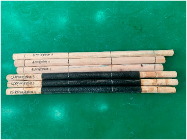
The wood selected for this experiment is Shandong cedar from Lishui City, chosen to closely match practical conditions, as this type of wood is commonly used in the construction of wooden arch corridor bridges. The physical and mechanical properties determined by wood testing methods are shown in Table 1. Six middle-section seedlings were fabricated for the three-segment arch bridge, consisting of three unreinforced components and three reinforced components, each illustrated in Figure 3. Figure 4 presents the moisture content of the wooden components reinforced with CFRP and those that are unreinforced. The selected moisture content reflects the levels typically encountered in the environmental conditions to which the wood is exposed, simulating the performance of CFRP reinforcement under normal drying conditions.
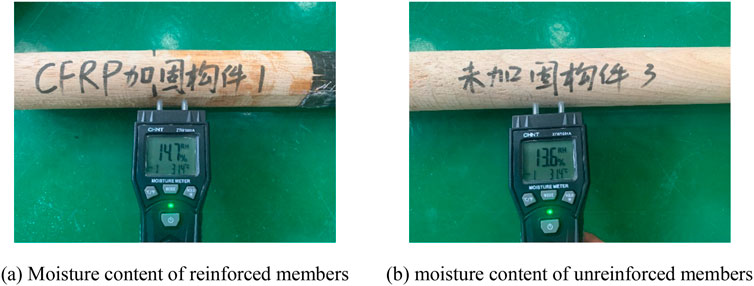
Figure 4. Moisture content of components of timber-arched lounge bridge. (A) moisture content of reinforced members. (B) moisture content of unreinforced members.
The moisture content of the wooden arch bridge components was measured using the ZTW1601a wood moisture tester produced by Zhengtai Network Technology Co., Ltd. The CFRP used in the experiment was carbon fiber cloth produced by Shanghai Zhinuo Decoration Materials Co., Ltd., with a model specification of Grade I 58,788 (200 g); the adhesive was epoxy resin impregnated adhesive produced by Shanghai Zhino Decoration Materials Co., Ltd., with a model of ZN-700. It consists of two components, A and B, mixed in a ratio of A:B = 2:1. The mechanical properties of CFRP and adhesive were tested by the National Building Materials Testing Center on behalf of the company. The test results are shown in Table 2.
2.2 Loading scheme and measurement scheme
The experiments were performed using a 5000 kN hydraulic testing machine at the Structural Laboratory of Lishui University. The loading process entailed concentrated loading at two points on the beam, with preliminary loading of the specimen to mitigate local voids and minimize their impact on the test results. Subsequently, graded loading was applied until failure ensued.
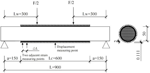
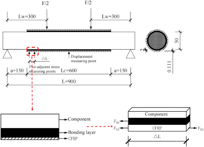
During the experiment, measurements primarily encompassed the mid-span displacement of the wooden arch bridge components, strain at mid-span cross-sections, and strain at adjacent points of CFRP bonding termination. Observations and records of damage to the wooden arch bridge components during loading were also conducted. The arrangement of the loading device and measurement points is depicted in Figure 5.
2.3 Theoretical analysis of elastic modulus of bonding interface
The components of the wooden arch bridge were reinforced using carbon fiber cloth. This paper conducted theoretical analysis on the small range of the two end points, as shown in Figure 6 (unit: mm).
For the small cross-sectional analysis around adjacent measurement points, it is assumed that after CFRP reinforcement of the wooden arch bridge components, the strain between the adjacent measurement points exhibits linear variation, meaning that the shear stress at the bonding interface between adjacent measurement points remains constant. The shear stress within this range can be obtained through the equilibrium relationship between adjacent CFRP points, namely, the average bonding interface shear stress τ. Assuming the distance between the two points is
Where FN1 and FN2 are the axial forces of adjacent measuring points respectively; FNb is the axial force of the bonding interface layer.
According to Equations 1, 2, order
Where EC is the elastic modulus of CFRP;
According to Equation 3, the shear stress of the bonding interface of the member under different loads can be calculated.
The components of wooden arch corridor bridge are strengthened with CFRP, and the micro elements of two adjacent measuring points dx are taken, then the shear strain γ of the bonding layer is:
where i(x,y) and j(x,y) are the horizontal and vertical displacement of the bonding layer respectively. According to Equation 3, the shear stress τ(x) at the bonding interface is:
where GA is the shear modulus of the bonding layer. It is assumed that the horizontal displacement of the bonding layer is linearly distributed along the vertical, that is:
where iC(x) and JW(x) are the horizontal displacement of the outer surface and inner surface of the bonding layer respectively, that is, the horizontal displacement of the inner surface of CFRP and the outer surface of wood beam respectively; δA is the thickness of the tack coat. Substituting Equation 6 into Equation 5 and deriving, it obtains:
Since the influence of shear deformation is very small, the shear deformation of single member of wooden arch corridor bridge and CFRP is ignored, then:
where FNC(x) and FNW(x) are the axial forces of CFRP and wooden arch corridor bridge components respectively; MC(x) and MW(x) are the bending moments of CFRP and wooden arch corridor bridge members respectively; EC and EW are the elastic modulus of CFRP and timber-arched lounge bridge members respectively; AC and AW are the sectional areas of CFRP and wooden arch corridor bridge components respectively; IC and IW are the section moment of inertia of CFRP and timber-arched lounge bridge components respectively; δC and δA are the thickness of CFRP and bonding layer respectively, and δ is the diameter of the member.
Because the stiffness and shear capacity of CFRP are very small, the bending moment and shear force borne by CFRP are ignored, that is:
According to the relationship between curvature and bending moment in material mechanics:
The equation for EI represents the total section bending stiffness, where EC, EA and EW denote the elastic modulus of CFRP, the elastic modulus of the bonding layer, and the elastic modulus of the wooden arch corridor bridge components, respectively; IA signifies the cross-sectional moment of inertia of the bonding layer. By substituting Equation 8–13 into Equation 7, we can obtain:
By deriving from both sides of Equation 14:
Considering the balance of micro elements, it can be obtained that:
Order:
According to Equations 15–19, can be obtained:
Equation 20 is the governing differential equation of shear stress at the bonding interface, and its solution is:
where C1 and C2 are coefficients, which can be obtained according to the two-point centralized loading, and the two-point centralized loading of wooden arch corridor bridge components as shown in Figure 6. In the shear span, q(x) = 0, FS(x) = F/2; In the pure bending section, q(x) = 0, FS(x) = 0. Substituting it into Equation 21, the interfacial shear stress is:
The boundary conditions are:x = LC/2; τ(LC/2) = 0; x = LW-a;
Order:
Obtain:
According to the boundary conditions:
Where a is the distance from the end of CFRP to the support; LW is the distance from the action point of concentrated load to the support; LC is the length of the CFRP.
3 Test results and analysis
When selecting components for the wooden arch corridor bridge, those without decay, nodes, or surface damage exhibit consistent test results. Hence, this paper analyzes the test outcomes of unreinforced component 1 and reinforced component 1. Figure 7A illustrates the failure mode of the member not strengthened with CFRP under load, while Figure 7B depicts the failure mode of the member reinforced with CFRP under load.
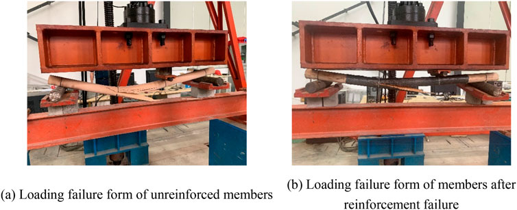
Figure 7. Failure mode of member. (A) loading failure form of unreinforced members. (B) loading failure form of members after reinforcement failure.
From Figure 7, it is evident that the failure mode of the wooden arch corridor bridge members under load is characteristic shear bending failure, with the members exhibiting longitudinal fiber fracture. The failure mode of the members after CFRP reinforcement is similar to that before reinforcement, as they are destroyed along the original section. During the test process, the members exhibit significant deflection under load before failure. However, after failure, the deflection produced by CFRP reinforcement under load is smaller than that of the former.
The failure form of undamaged members strengthened with CFRP under load is shown in Figure 8.
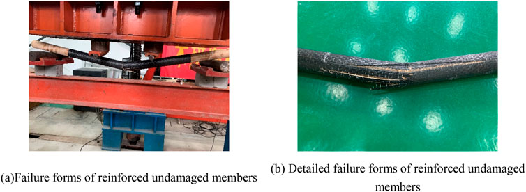
Figure 8. Failure mode of CFRP strengthened members. (A) failure forms of reinforced undamaged members. (B) detailed failure forms of reinforced undamaged members.
As observed in Figure 8, undamaged members of the wooden arch bridge, reinforced with CFRP, exhibit fracture in the middle under load. The upper part experiences shear failure, while the lower part undergoes tensile failure. Upon loading to a certain extent, a brittle crack sound of CFRP extrusion failure is audible, followed by the sound of wood cracking after continuous loading.
From the comparison of Figures 7, 8, it can be observed that the CFRP-reinforced damaged wooden components exhibit different failure modes compared to the unreinforced wooden components. For the CFRP-reinforced damaged wooden components, the failure mode resembles that of the original wooden components, characterized by a distinct ductile failure, with minimal differences in ductility under loading when compared to the unreinforced wooden components. In contrast, the CFRP-reinforced undamaged wooden components display a failure mode similar to brittle fracture, indicating that the incorporation of CFRP reduces the ductility of the wooden components. The difference between these two failure modes lies in the presence of gaps in the CFRP-reinforced damaged components, which results in less secure wrapping of the CFRP and allows for some degree of deformation. For the undamaged wooden components reinforced with CFRP, there are essentially no gaps, and since the ductility of CFRP is lower than that of wood, the deformation range after reinforcement is smaller, exhibiting a brittle failure pattern. When applying CFRP reinforcement to the components of wooden arch corridor bridges, it is not necessary to achieve a tight wrap, allowing for the retention of certain gaps.
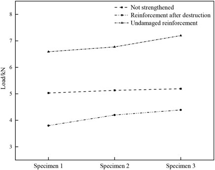
The comparison of Figures 7–9 reveals significant reinforcement of the timber-arched lounge bridge members with CFRP. After being strengthened with CFRP, the bearing capacity of completely damaged members can reach 75%–85%, while that of undamaged members can reach 130%–140%.
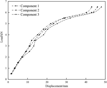
The load displacement curve of undamaged members of CFRP strengthened wooden arch bridge is shown in Figure 10.
From Figure 10, it is evident that the wood arch bridge, reinforced with CFRP, exhibits no damaged members. In the initial loading phase, displacement changes linearly, indicating strong adhesion between CFRP and the members. As loading progresses, the rate of displacement increase slows down until the undamaged member reinforced with CFRP fails upon reaching the ultimate load.
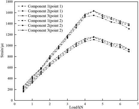
The strain load curves of two adjacent measuring points at the end of undamaged members of CFRP strengthened wood arch bridge are shown in Figure 11.
Figure 11 illustrates that the change trends of the two measurement points remain largely consistent throughout the entire loading process. Initially, the load strain of both measuring points changes linearly, indicating effective bonding performance between CFRP and the undamaged member. However, as the load continues to increase, the rate of CFRP strain growth slows down, lagging behind the load increase rate. This suggests shear deformation occurring in the bonding layer, leading to slip between CFRP and the undamaged members. The shear stress at the bonding interface between CFRP and undamaged members can be computed based on the strain of adjacent measuring points of undamaged members reinforced with CFRP under the same load.
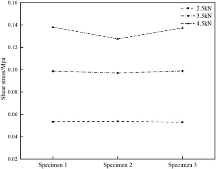
The shear stress of bond interface of undamaged members of wood arch bridge strengthened with CFRP under different loads is shown in Figure 12.
The shear stress values in Figure 12 are computed based on Formula 3 in the text. The shear stress at the bonding interface of three undamaged members reinforced with CFRP under identical loads remains consistent. However, the bonding interface shear stress of these members varies under different loads, increasing with higher loads. The test results indicate minimal discrepancies among the bonding interface shear stresses of the three undamaged members reinforced with CFRP, suggesting the measured values in this test are reasonably feasible.
The interface bonding layer is applied twice. By measuring the thickness of the bonding layer δA = 2mm, the average elastic modulus of the bonding interface of timber-arched lounge bridge members strengthened with CFRP EA = 1852.5 MPa is calculated according to Equation 22 and experimental results.
4 The application of CFRP in reinforcing wooden arch bridge
4.1 Experimental testing of wooden arch bridge arches
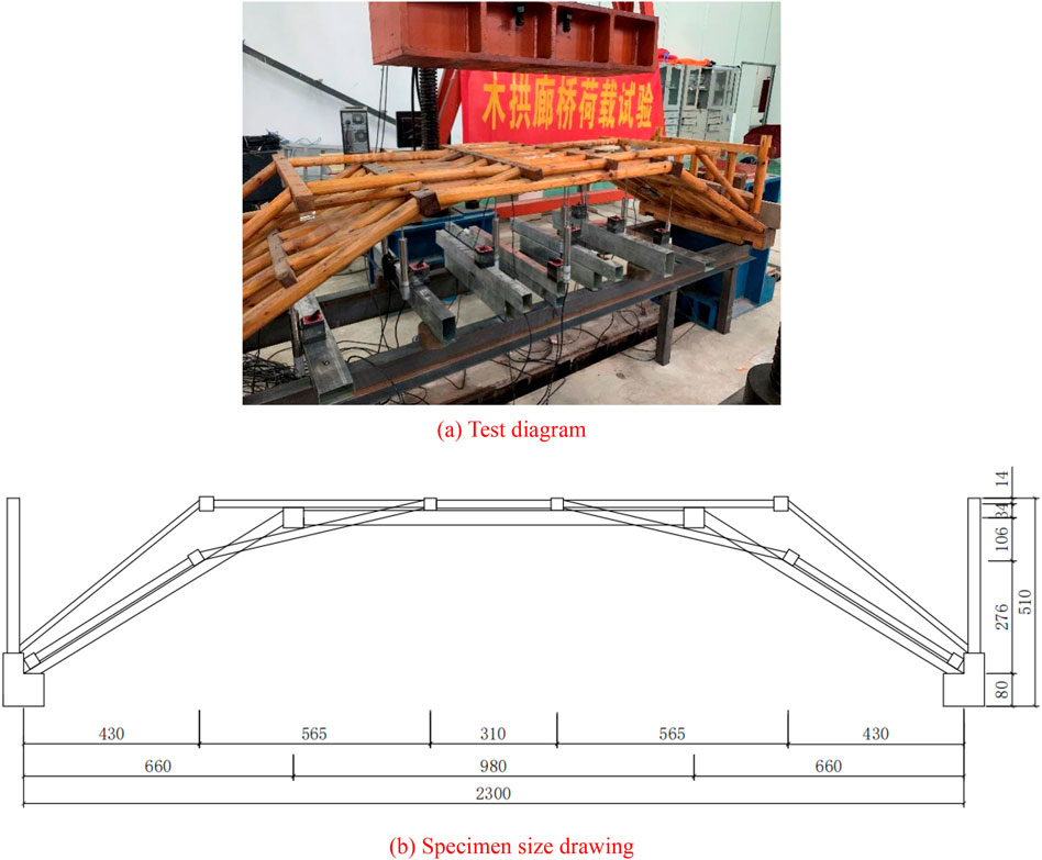
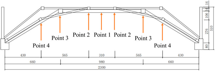
The 1:5 scale model of the wooden arch bridge was placed under the MTS hydraulic testing machine for load testing, as shown in Figure 13. The displacement measurement points for the load test of the wooden arch bridge arches are illustrated in Figure 14.
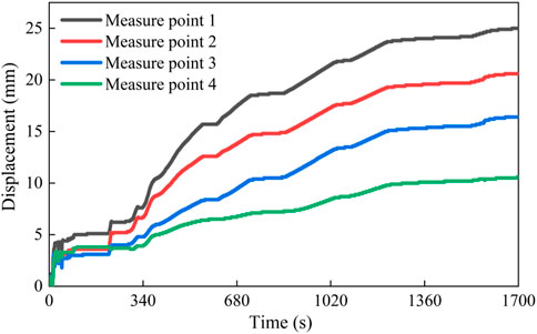
Static load test was conducted on the wooden arch bridge arches, and the displacements at each measurement point are shown in Figure 15.
From Figure 15, it can be observed that the displacement curves at each measurement point exhibit a similar trend under static loading. The maximum displacement occurs at the mid-span of the wooden arch bridge arches under static loading, gradually decreasing towards the sides. This trend indicates that during flood periods when additional loads are applied to prevent the bridge from being washed away, reducing the load at the mid-span while distributing it towards the sides may be advisable.
4.2 CFRP reinforcement of the wooden arch bridge arches
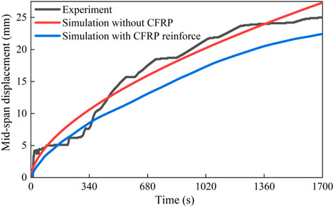
A numerical model of the wooden arch bridge was established using SAP 2000, as shown in Figure 16A. The established numerical model was compared with the experimental results to validate its accuracy, and the obtained displacements are illustrated in Figure 16B.
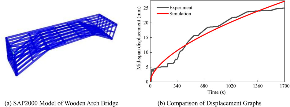
Figure 16. Comparison between Load tests and simulations of wooden arch bridge frameworks. (A) SAP2000 model of wooden arch bridge (B) comparison of displacement graphs
As shown in Figure 16A, during the numerical modeling of the wooden arch corridor bridge using SAP 2000, the deck beams were modeled; however, since there were no deck beams in the experiments, the deck beams were assumed to bear no loads during the numerical calculations. Additionally, each node was subject to a relaxation of constraints, allowing for a limited movement of 5 mm in all six degrees of freedom, changing the constraints from fixed to movable. The current model is suitable for the performance of the specimens tested; however, its generalizability needs to be enhanced through additional experiments with different specimens for parameter calibration. As indicated in Figure 16B, the numerical model of the wooden arch bridge framework established using SAP2000 demonstrates a close agreement in mid-span displacement under static loading, indicating a certain level of accuracy in the model.
Using the data obtained from the CFRP reinforcement of components in Section 2, the spring elements representing CFRP are attached to the mid-span nodes of the wooden arch bridge framework and subjected to load simulation, with results shown in Figure 17.
From Figure 17, it is evident that the application of CFRP reinforcement significantly enhances the load-bearing capacity of the wooden arch bridge, resulting in a substantial reduction in mid-span displacement under the same load conditions. CFRP reinforcement of the wooden arch bridge’s framework can increase its load-bearing capacity by 20%. When subjected to flood periods, CFRP reinforcement of the wooden arch bridge’s framework ensures its structural integrity under applied loads.
5 Conclusion
Based on the experimental research and theoretical analysis of timber-arched lounge bridge members reinforced with CFRP, the following conclusions are drawn:
(1) Based on the comparison between the test results and theoretical research, the elastic modulus of the bonding interface is determined, providing an accurate value for subsequent establishment of the finite element model of local damage of timber-arched lounge bridge components and the setting of component interface parameters for CFRP reinforcement EA = 1852.5 MPa.
(2) The failure modes of CFRP-reinforced damaged wooden components and undamaged wooden components exhibit significant differences. Given that CFRP has lower ductility compared to wood, when reinforcing the components of wooden arch corridor bridges with CFRP, it is advisable to leave small gaps. This approach allows the reinforced components to retain a certain degree of ductility, thereby preventing failure modes resembling brittle fracture and providing practical guidance for application.
(3) The local components of the wooden arch corridor bridge are damaged and can be reinforced with CFRP to restore their load-bearing capacity. It exhibits excellent reinforcement performance, allowing the components to retain 75%–85% of their original load-bearing capacity after reinforcement. During flood periods, when the load on the wooden arch corridor bridge increases, local members may experience insufficient load-bearing capacity and excessive deformation. CFRP reinforcement can address this issue, increasing the load-bearing capacity to 130%–140% of the original level.
(4) The application of CFRP to the framework of wooden arch bridges has shown promising reinforcement effects, capable of enhancing the load-bearing capacity of the wooden arch bridge framework by approximately 20%, thus providing a theoretical basis for the reinforcement of wooden arch bridge frameworks.
For ancient wooden bridges, the use of CFRP for reinforcement and the reinstallation of components after replacement hold significant value in preserving their original appearance and maintaining their integrity. Additionally, given that wooden bridges are situated above rivers, the durability of CFRP reinforcement in moist environments also requires urgent investigation.
Data availability statement
The original contributions presented in the study are included in the article/supplementary material, further inquiries can be directed to the corresponding authors.
Author contributions
LL: Data curation, Formal Analysis, Project administration, Supervision, Validation, Writing–original draft, Writing–review and editing. YW: Funding acquisition, Methodology, Visualization, Writing–original draft, Writing–review and editing. YZ: Formal Analysis, Methodology, Writing–original draft, Writing–review and editing. XW: Data curation, Formal Analysis, Validation, Writing–original draft. GJ: Data curation, Formal Analysis, Methodology, Project administration, Supervision, Validation, Writing–original draft. XL: Conceptualization, Data curation, Formal Analysis, Investigation, Methodology, Project administration, Resources, Supervision, Validation, Writing–original draft.
Funding
The author(s) declare that financial support was received for the research, authorship, and/or publication of this article. The writers gratefully acknowledge the financial support of Scientific research project from Zhejiang earthquake administration (No. 2023zjj02); Zhejiang science and technology planning project (No. 2013C33075); Innovation training program for college students (No. 202010352016).
Conflict of interests
Author XW was employed by Beijing Glory PKPM Technology Company Limited.
The remaining authors declare that the research was conducted in the absence of any commercial or financial relationships that could be construed as a potential conflict of interest.
Publisher’s note
All claims expressed in this article are solely those of the authors and do not necessarily represent those of their affiliated organizations, or those of the publisher, the editors and the reviewers. Any product that may be evaluated in this article, or claim that may be made by its manufacturer, is not guaranteed or endorsed by the publisher.
References
A, S. H., Zhou, C. D., and Yang, L. G. (2021). Experimental study on axial compression behavior on circular timber columns strengthened with CFRP strips and near-surface mounted steel bars. J. Struct. Eng. 147 (3), 1–12. doi:10.1061/(asce)st.1943-541x.0002931
Bashandy, A. A., El-Habashi, A. E., and Dewdar, A. K. (2018). Repair and strengthening of timber cantilever beams. Wood Material Sci. & Eng. 13 (4), 241–253. doi:10.1080/17480272.2017.1366944
Brol, J., and Agnieszka, W. P. (2019). Old timber reinforcement with FRPs. Materials 12 (24), 4197. doi:10.3390/ma12244197
Buell, T. W., and Saadatmanesh, H. (2005). Strengthening timber bridge beams using carbon fiber. J. Struct. Eng. 131 (1), 173–187. doi:10.1061/(asce)0733-9445(2005)131:1(173)
Dagher, H. J., and Lindyberg, R. (2004). FRP-wood hybrids for bridges: a comparison of E-glass and carbon reinforcements. Adv. Technol. Struct. Eng., 1–8. doi:10.1061/40492(2000)191
Dai, T. W., Ji, T., Zhang, Y., and Zhuang, Y. Z. (2015). Experimental study on the effect of the number of layers of carbon fiber cloth on the flexural performance of mortise and tenon timber beams. J. Fuzhou Univ. Nat. Sci. Ed. 43 (02), 225–230. doi:10.7631/issn.1000-2243.2015.02.0225
Guo, Y., Liu, R. J., Song, Y., Li, Y. H., and Yao, L. H. (2020). Research progress on seismic performance and post earthquake reinforcement and repair of tenon and mortise joints of wood structures. For. Prod. Ind. 57 (04), 25–28. doi:10.19531/j.issn1001-5299.202004005
İşleyen, K. U., Ghoroubi, R., Mercimek, Ö., Anıl, Ö., Togay, A., and Erdem, R. T. (2021). Effect of anchorage number and CFRP strips length on behavior of strengthened glulam timber beam for flexural loading. Adv. Struct. Eng. 24 (9), 1869–1882. doi:10.1177/1369433220988622
Jin, Y. C., Su, H. X., Pan, W., He, Y. C., Du, J. W., and Fu, G. P. (2022). Experimental research on seismic performance and reinforcement comparison of mortise-tenon and joints in timber structures. J. Civ. Environ. Eng. 44 (02), , 138–147. doi:10.11835/j.issn.2096-6717.2021.095
Klaudia, S. W., Adam, O. K., Justyna, J. L., and Karolak, A. (2021). The influence of CFRP sheets on the load-bearing capacity of the glued laminated timber beams under bending test. Materials 14 (14), 4019. doi:10.3390/ma14144019
Li, A. Q., Zhou, K. P., Wang, C. C., and Xie, L. L. (2019). Analysis and Prospect of wood structure repair and reinforcement technology of Chinese ancient buildings. J. Southeast Univ. Nat. Sci. Ed. 49 (01), 195–206. doi:10.3969/j.issn.1001-0505.2019.01.027
Lin, H. Y., Ji, T., Dai, T. W., Lin, X. J., and Zhang, Y. (2016). Experimental study for the effect of dovetail style on the flexural behavior of timber beams extended by a mortise-tenon joint and strengthened by CFRP sheets. J. Fuzhou Univ. Nat. Sci. Ed. 44 (04), 524–530. doi:10.7631/issn.1000-2243.2016.04.0524
Qiu, Z., Yan, M., Yang, Y., Li, J., Zhu, W., and Fan, H. (2021). Flexural behaviors of CFRP strengthened laminated bamboo arches. Constr. Build. Mater. 305, 124759. doi:10.1016/j.conbuildmat.2021.124759
Rescalvo, F. J., Valverde-Palaacios, I., Elisabet, S., and Gallego, A. (2018b). Experimental and analytical analysis for bending load capacity of old timber beams with defects when reinforced with carbon fiber strips. Compos. Struct. 186, 29–38. doi:10.1016/j.compstruct.2017.11.078
Rescalvo, F. J., Valverde-Palacios, I., Elisabet, S., Roldán, A., and Gallego, A. (2018a). Monitoring of carbon fiber-reinforced old timber beams via strain and multiresonant acoustic emission sensors. Sensors 18 (4), 1224. doi:10.3390/s18041224
Tohid, G. G., Russo, T., and Valipoue, H. R. (2020). Lightweight timber I-beams reinforced by composite materials. Compos. Struct. 233, 111579. doi:10.1016/j.compstruct.2019.111579
Vahedian, A., Shrestha, R., and Crews, K. (2019). Experimental and analytical investigation on CFRP strengthened glulam laminated timber beams: full-scale experiments. Compos. Part B 164, 377–389. doi:10.1016/j.compositesb.2018.12.007
Wang, S. Y., Guo, T., Deng, H., and Zhou, H. B. (2021). Study on seismic performance of mortise and tenon joint reinforcement of bucket type wood structure. Wood Sci. Technol. 35 (01), 36–41. doi:10.12326/j.2096-9694.2020026
Xie, Q. F., Zhao, H. T., Xie, J. Y., Wu, J. B., and Sui, Y. (2008). Experimental study and theoretical analysis on interfacial bond stress of timber beams strengthened with CFRP sheets. Eng. Mech. (07), 229–234+240.
Xue, J. Y., Zhai, L., Zhang, F. L., and Li, Y. Z. (2015). Performance analysis and design method of damaged joints of wood structures of ancient buildings strengthened with flat steel. J. Xi'an Univ. Archit. Technol. Nat. Sci. Ed. 47 (05), 621–625. doi:10.15986/j.1006-7930.2015.05.002
Yuan, S. C., Dong, J. F., Wang, Q. Y., and Zhu, Y. M. (2014). Calculation and analysis on load carrying capacity of damaged timber beams strengthened with CFRP. Appl. Math. Mech. 35 (S1), 261–265.
Zhang, L., Zhou, A. P., Sheng, B. L., Shen, Y. R., and Xu, J. N. (2018). Experimental study on wood beams with defects strengthened with carbon fiber composites. J. For. Eng. 3 (03), 128–135. doi:10.13360/j.issn.2096-1359.2018.03.021
Zhou, C. D., Liang, L. C. A. S. H., Zhang, Y., and Yang, L. G. (2020). Experimental study on axial compression performance of rectangular section wood columns strengthened with embedded reinforcement and wrapped CFRP. J. Build. Struct. 41 (07), 173–181. doi:10.14006/j.jzjgxb.2018.0517
Zhou, T. G., Zhu, R. Z., Zhu, L. X., Yu, W., and Zuo, D. L. (2016). Shaking table test study on seismic reinforcement of adobe retaining wall wood structure residential buildings. J. Xi'an Univ. Archit. Technol. Nat. Sci. Ed. 48 (03), 346–350 + 370. doi:10.15986/j.1006-7930.2016.03.007
Keywords: CFRP, wooden arch bridge, elastic modulus of bonding interface, experimental study, reinforce
Citation: Li L, Wang Y, Zhang Y, Wang X, Ji G and Li X (2024) Study on increasing load capacity of wooden arch bridge by CFRP strengthening: experimental and numerical Verification. Front. Mater. 11:1486225. doi: 10.3389/fmats.2024.1486225
Received: 25 August 2024; Accepted: 16 September 2024;
Published: 02 October 2024.
Edited by:
Abdelmoumen Anis Bousahla, University of Sidi-Bel-Abbès, AlgeriaReviewed by:
Syahrul Fithry Senin, Universiti Teknologi Teknologi MARA, MalaysiaAmir Ali Shahmansouri, Washington State University, United States
Copyright © 2024 Li, Wang, Zhang, Wang, Ji and Li. This is an open-access article distributed under the terms of the Creative Commons Attribution License (CC BY). The use, distribution or reproduction in other forums is permitted, provided the original author(s) and the copyright owner(s) are credited and that the original publication in this journal is cited, in accordance with accepted academic practice. No use, distribution or reproduction is permitted which does not comply with these terms.
*Correspondence: Yan Wang, MTU4Mzg2MjU4QHFxLmNvbQ==; Yafei Zhang, emhhbmd5Zjk1QHRqdS5lZHUuY24=
 Liping Li1
 Yafei Zhang