 Yuefu Yang
 Chaohe Chen2*
- 1School of Naval Architecture and Ocean Engineering, Naval University of Engineering, Wuhan, China
- 2School of Civil Engineering and Transportation, South China University of Technology, Guangzhou, China
This paper reviews the state-of-the-art progress of research into corrosion fatigue on marine structures, both theoretical and experimental. This includes corrosion fatigue life prediction models/methods, load–environment interaction/coupling test methods, accelerated corrosion methods in corrosion fatigue testing, fatigue crack measurement, and corrosion fatigue life assessment in the whole life period. To date, some theoretical models and methods for predicting the corrosion fatigue life of metallic materials or structures have been proposed and applied. Meanwhile, load–environment interaction/coupling testing on metallic material specimens has been maturely developed and widely applied. Some newly developed corrosion fatigue theoretical and experimental methods, based on data-driven machine learning and at-sea monitoring, have received preliminary application. This review of accelerated corrosion methods, fatigue crack measurement methods, and corrosion fatigue life assessment for marine structures in the whole-life period has been undertaken by extensive reference to relevant studies conducted worldwide. Challenges and recommendations for further developing and improving corrosion fatigue assessment methods and test techniques are also reported and discussed.
1 Introduction
The marine environment is a highly corrosive natural environment. According to Hou et al. (2016), worldwide average corrosion loss accounts for about 3.4% of global gross domestic product, and more than 30% of this is due to marine corrosion. The marine environment can be vertically divided into five zones, and the harsh degree of each corrosion zone can be respectively sequenced as splash, tidal, immersion, mud, and atmospheric zones from severe to slight (Hou et al., 2016).
Marine corrosion not only causes significant economic loss but also poses a serious threat to the service safety of marine structures. Even with anti-corrosion treatment during the construction of marine structures, different degrees of corrosion damage will occur as the service life progresses (Figure 1).
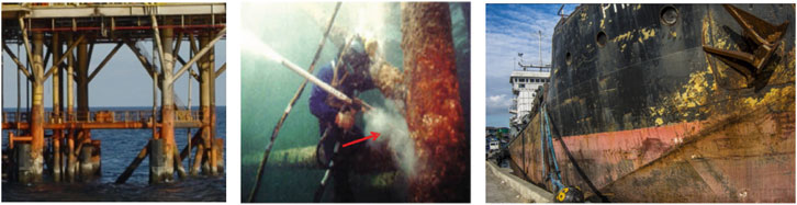
Figure 1. Corrosion phenomena of different marine structures.
In addition to corrosion damage, various types of marine structures in service will suffer from fatigue damage caused by environmental/fatigue loads. Failure phenomena in engineering structures due to cracking or fracture under the combined action of fatigue load and environmental corrosion are referred to as “corrosion fatigue” (Wu, 1989; Wang, 2001). In the corrosion fatigue process, the relationship between corrosion damage and fatigue damage is not simply a superposition but one interactively promotes the other (Wang, 2001). The corrosion fatigue problem in metallic material structures is extremely complex, involving interdisciplinary theoretical disciplines such as corrosion electrochemistry and mechanics. As shown in Figure 2, the corrosion fatigue failure process of metallic materials can be distinguished into four stages: surface film rupture, pitting formation, crack initiation from pits, and crack growth (Akid, 1996).
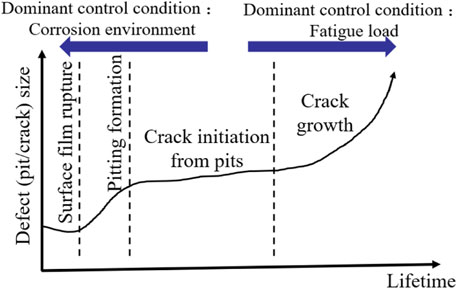
Figure 2. Corrosion fatigue failure process of metallic materials.
Corrosion fatigue is the main challenge faced by marine structures during service, and it is also the most important factor leading to structural failure. Therefore, a comprehensive and accurate evaluation of the corrosion fatigue performance of marine structures has always been an important subject in the field of marine engineering. According to the logical framework shown in Figure 3, this current review summarizes and analyzes the current research status at home and abroad. Furthermore, it also highlights the shortcomings of existing research and the directions that still require further study.
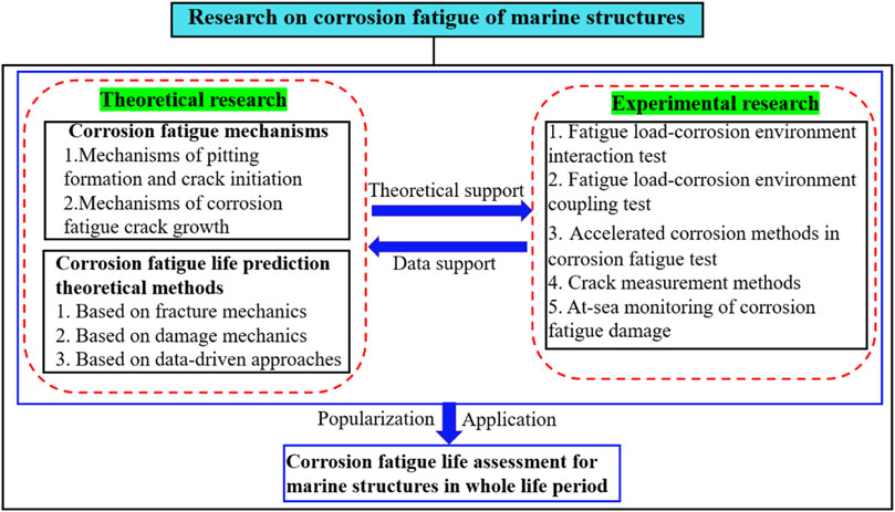
Figure 3. Framework of research on corrosion fatigue of marine structures.
2 Corrosion fatigue mechanism of marine structure materials
Clearly understanding the corrosion fatigue mechanism of materials is a prerequisite for conducting corrosion fatigue life analysis and prediction. In terms of the development and progression of corrosion fatigue, the mechanisms can be studied from two stages: pitting formation and crack initiation, and crack growth.
2.1 Mechanism of pitting formation and crack initiation
With the gradual accumulation of fatigue damage, slip bands will form on a metal surface and cause electrochemical inhomogeneity. In corrosive environments, localized dissolution occurs at the uneven electrochemical areas, resulting in pitting formation. The morphology of pits undergoes continuous evolution, and pits will transform into cracks when they reach a critical state (Huang and Wang, 2016).
For most metallic materials, pitting formation is the primary factor that induces crack initiation. There are two main criteria for determining pit-to-crack formation:
(1) Kondo (1989) proposed the stress intensity factor criterion based on the competitive mechanism between pitting evolution and corrosion fatigue crack growth (Eq. 1):
where ΔK is the stress intensity factor range at the root of the pit, which increases continuously with the evolution of the pit. △Kth denotes the threshold value for corrosion fatigue crack growth in the material, which is typically considered a constant.
(2) Huang and Wang (2016) proposed the energy criterion based on the energy principle in the pitting evolution process (Eq. 2):
where
As shown in Figures 4A–D, the pit evolution and crack initiation process in stainless steel materials under different load cycles are well demonstrated (Ebara, 2006). It can be observed that when the morphology/size of the pit evolves to a certain extent, the pit transforms into a crack. Sadananda and Vasudevan (2020) indicated that the pit-to-crack transition can be divided into two steps (Figure 5). 1) The crack first grows on the surface of the pit until it becomes semi-elliptical in shape. 2) Uniform expansion of the semi-elliptical crack follows.
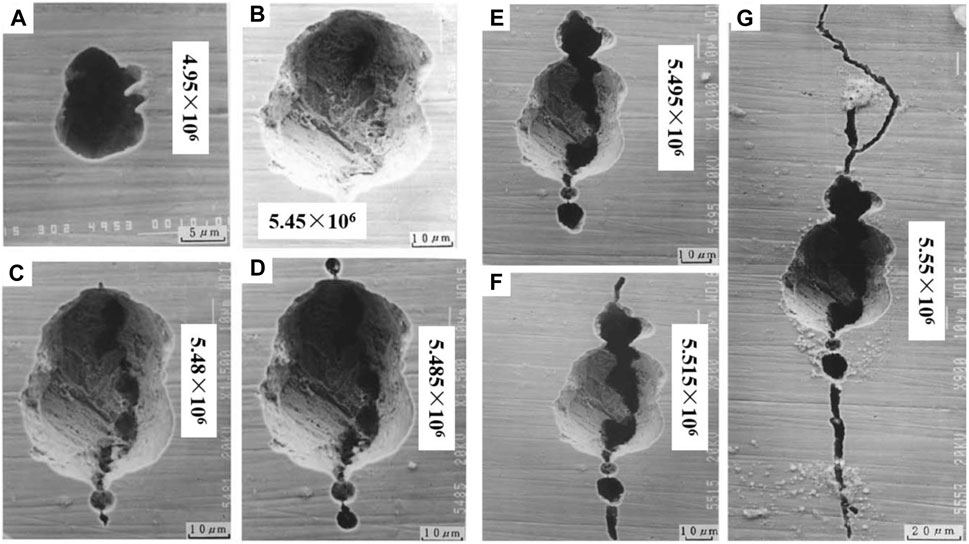
Figure 4. Process of pitting evolution and crack nucleation and propagation (Ebara, 2006).
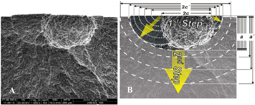
Figure 5. Example of pitting transformed into cracking (Sadananda and Vasudevan, 2020).
The initiation of corrosion fatigue cracks is a localized process, and there are currently multiple explanations of its mechanisms (Wang Q. S. et al., 2023; Xu H. H. et al., 2023):
2.1.1 Pitting stress concentration theory
In the early stages of corrosion fatigue, electrochemical corrosion plays a dominant role, and the formation of pitting on the electrochemically heterogeneous metal surface leads to stress concentration, thereby promoting crack initiation. This theory is widely applicable to most metallic materials and is commonly used; examples are crack initiation at pits observed through X-ray computed tomography (Turnbull, 2014) (Figure 6A), the microscopic morphology of crack-pits in X80 steel (Zhao et al., 2012a) (Figure 6B), and the process of crack propagation at pits (Figures 4E–G). While all confirm the compatibility of this theory, it is not applicable to easily passivated metals that are insensitive to pitting.
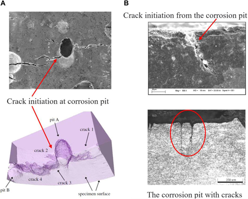
Figure 6. Crack initiation due to pitting (Zhao et al., 2012a; Turnbull, 2014).
2.1.2 Slip band preferential dissolution theory
This theory proposes that the accumulation of fatigue damage leads to the formation of slip bands and the creation of anodic zones on the metal surface. The anodic zone will undergo dissolution in the corrosive environment, resulting in fatigue crack formation. This theory provides a reasonable explanation for the crack initiation mechanism in pitting-insensitive materials.
2.1.3 Protective film rupture theory
The protective film on a metal surface will rupture under external loads and form a primary cell. The exposed metal acts as the anode and undergoes dissolution until the protective film is repaired again. This cyclic process leads to the initiation of fatigue cracks.
2.1.4 Adsorption theory
Metallic materials adsorb active substances from the corrosive medium, leading to a decrease in surface energy and the initiation of cracks under the influence of fatigue loading. This theory is applicable to study of the corrosion fatigue mechanism in hydrogen-rich environments.
2.2 Corrosion fatigue crack growth mechanism
This mechanism mainly includes oxide film rupture–anodic dissolution, hydrogen-induced cracking, and a combination of both (Zhao et al., 2012b; Nam et al., 2015). Chen (2016) has proposed several factors that could promote corrosion fatigue crack propagation:
(1) repeated formation of a fresh metal surface at the crack tip;
(2) repeated rupture of passivating films at the crack tip;
(3) influence of adsorbed corrosion products on the plastic zone of the crack, thereby increasing the crack growth rate;
(4) anodic dissolution of the metal at the crack tip;
(5) outward transfer and delivery of corrosion products towards the crack tip;
(6) effects of corrosion product accumulation at the crack tip.
These six factors are dependent on the specific “material–environment” combination. Previous studies have indicated that for marine structural steels exposed to seawater, the primary mechanisms of corrosion fatigue crack growth are anodic dissolution and hydrogen embrittlement. Huang (2013) found that both anodic dissolution and hydrogen embrittlement contribute to corrosion fatigue crack growth, but their respective contributions vary depending on the material and corrosion environment. In conclusion, the mechanism of corrosion fatigue crack growth exhibits strong dependence on the “material–environment” combination, and there is currently no universally applicable mechanism that can explain this phenomenon in metallic materials.
3 Corrosion fatigue life prediction methods for marine structure materials
The analysis and prediction of the corrosion fatigue life of metallic materials or structures involve interdisciplinary theoretical foundations such as mechanics and electrochemistry. Existing corrosion fatigue life prediction models and methods are mainly derived and developed based on fracture mechanics and damage mechanics theory. However, the current theoretical models and methods still involve a significant amount of simplification and assumption. With the application and promotion of big data technology, data-driven approaches for life prediction have emerged which rely on limited experimental data for inverse analysis without explicitly considering the corrosion fatigue mechanism.
3.1 Corrosion fatigue life prediction method based on fracture mechanics
Fracture mechanics addresses the crack growth life of cracked bodies and is not suitable for analyzing crack initiation life. The initiation of corrosion fatigue cracks is often studied using pit growth models based on corrosion kinetics theory. However, in current research, the stress intensity factor criterion is commonly used to determine the transition from pits to cracks, and the life before the transition is assumed as the crack initiation life. This combines fracture mechanics theory with corrosion kinetics theory.
Li and Akid (2013) defined the total corrosion fatigue life N of carbon steel materials as the sum of the pit crack nucleation life Ni, short crack growth life Ns, and long crack growth life Nl (Eq. 3):
where the life prediction models of each stage are as follows (Eqs 4, 5):
where
Similarly, Harlow and Wei (1994) divided total corrosion fatigue life into three stages: pit formation to surface crack initiation (tth); surface crack growth to through-crack formation (ttc); through-crack growth to failure (ttg). In the first stage, the life is analyzed by using the stress intensity factor threshold △Kth and a pit growth kinetics model based on Faraday’s law. It is assumed that the pit grows at a constant rate and remains semi-spherical throughout. The corresponding life is denoted as tth (Eq. 6):
The critical pit depth ath for the transition from pit to crack can be obtained from the relation ath ∝△Kth as follows (Eq. 7):
The life of the latter stage is predicted based on the generalized Paris equation thus (Eq. 8):
where
Based on Harlow’s research, Sriraman and Pidaparti (2010) considered the influence of fatigue load/stress on the life of the first stage and introduced stress influence factor C into the calculations (Eq. 9):
This method considers the combined effects of the corrosion environment and load on pit growth, hence improving the accuracy of predicting crack initiation life. However, the value of stress influence factor C is closely related to the range of stress and requires experimental identification for accurate estimation.
Mao et al. (2014) defined the shape parameter of the pit, denoted as
The crack initiation life corresponding to different ranges of λ are as follows (Eqs 11, 12):
where C is the stress influence factor,
In the above studies, the total corrosion fatigue life was divided into two parts: crack initiation and crack growth (including short and long cracks), with time tth of the occurrence of the critical pit depth ath as a dividing point. As shown in Figure 7, Goswami and Hoeppner (1995) provided a more detailed division with seven stages: pit initiation, pit growth, pit-to-crack transition, short crack growth, short-to-long crack transition, long crack growth, and fracture.
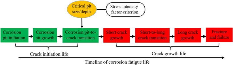
Figure 7. Division of corrosion fatigue life.
Based on above divisions, Shi and Mahadevan (2001) proposed a life prediction model consisting of four stages: pit initiation life (
where
Although this method is based on single-point corrosion damage, it improves the prediction accuracy to some extent for pit initiation life and short crack propagation life. Similarly, Wang et al. (2001) divided crack initiation life into pit initiation and crack initiation from pit, and provided the corresponding prediction model as follows (Eqs 15–17):
where
This prediction model further enhances the accuracy of predicting crack initiation life. However, the increased number of variable parameters in the model leads to higher computational complexity, and the generalizability of model parameters is limited.
Through the above prediction models, it can be observed that the threshold value of the stress intensity factor ΔKth is a crucial parameter, which is an important basis for dividing crack initiation life and growth life. However, in a corrosive environment, ΔKth exhibits a strong dependence on the material–environment–load combination, and its value can only be determined experimentally. Additionally, when calculating the corrosion fatigue crack growth life by using the generalized Paris equation, the influence of the corrosive environment on the crack growth rate can only be corrected through the model parameters C and m. However, quantifying the acceleration of fatigue damage caused by the corrosive environment and understanding the synergistic relationship between them still remains a technical challenge to be resolved.
3.2 Corrosion fatigue life prediction method based on damage mechanics
As mentioned above, the application of fracture mechanics makes it difficult to quantitatively describe the synergistic relationship between corrosion and fatigue. However, corrosion fatigue life prediction methods based on damage mechanics can somewhat quantify the relationship between corrosion and fatigue.
Zhang J. et al. (2018) considered the influence of corrosion on material performance degradation from the perspective of material fatigue limit. They established a functional relationship between the material fatigue limit, surface roughness, and corrosion time, and proposed a multi-axial fatigue damage evolution model that takes into account the effect of corrosion (Eq. 18):
where the fatigue limit
Miao and Lv (2019) characterized the degree of material corrosion damage using porosity and established a relationship (Eq. 19) between porosity (P), Young’s modulus (E), and a damage variable (D). They incorporated this relationship into the material constitutive equation, hence introducing the coupled effect of material corrosion damage into the fatigue damage evolution model.
where
Zhang F. et al. (2021) calibrated the relevant parameters of the uniaxial elastic damage evolution model (Eq. 20) based on material property and fatigue tests of smooth steel bars. They conducted fatigue tests on pitted steel bars with different pit shapes and stress ratios. The experimental results were numerically simulated and verified using the calibrated model parameters.
where D is the elastic damage variable, N is the load cycles,
Similarly, Cui et al. (2020) determined the evolution model of pits based on corrosion kinetics equations and studied the high-cycle fatigue damage of pitted steel bars, considering elastic–plastic effects by using a simplified uniaxial elastic and plastic damage evolution model (Eq. 21). The distribution of Von Mises stresses and damage near the pits under different corrosion times were simulated.
where De is the elastic damage variable, Dp is the plastic damage variable, N is the number of load cycles,
Under corrosive environments, the mechanical properties of materials will degrade to some extent. Appropriate damage variables can organically integrate corrosion and fatigue and characterize the coupling effect between the corrosive environment and fatigue load through the evolution of damage variables. However, the current damage evolution models have high computational complexity and require the calibration of numerous material parameters based on experiments. This limits the practical application of this theoretical approach, especially for the corrosion life prediction of in-service marine platform structures.
3.3 Corrosion fatigue life prediction method based on data-driven
Corrosion-fatigue life prediction methods based on fracture and damage mechanics mentioned above are referred to as physics-based model-driven methods. On the one hand, due to the numerous and interconnected factors that influence corrosion-fatigue life, the non-linear relationship between multidimensional influencing factors and fatigue life is difficult to describe using these methods. On the other hand, data-driven prediction methods do not rely on the specific mechanisms of corrosion-fatigue but generate corresponding prediction models by integrating large amounts of data. This approach has brought new ideas and methods to corrosion-fatigue life prediction.
The life prediction method based on data mainly includes statistically based and machine-learning-based approaches, with the latter being more advanced in terms of application. The general workflow of using machine learning methods for prediction is as follows (Xu H. H. et al., 2023): data acquisition, data preprocessing, feature extraction, model selection, model training and testing.
Cavanaugh et al. (2010) predicted the maximum pit depth and diameter of aluminum alloy materials by using the artificial neural network (ANN) model with input conditions including pH value, temperature, Cl− concentration of the corrosive solution, material orientation, and corrosion time. Co et al. (2018) employed two methods—random forest (RF) and logistic regression (LR)—to predict the correlation between macroscopic and microscale corrosion parameters of the material and the initiation of corrosion fatigue cracks. Pidaparti (2007) combined wavelet image processing, cellular automaton, and ANN models to predict the fatigue life, damage, and integrity of structures in corrosive environments. Variables such as the electrochemical parameters of a corrosive environment, material loss and residual strength, initial and failure crack sizes, and fatigue loading conditions were considered. Yang et al. (2021) proposed a novel approach for multi-axial fatigue life prediction with fully connected neural network (FCNN) and long short-term memory neural network (LSTM) methods. Their prediction method (Figure 8) overcomes the limitations of traditional prediction models that are restricted to specific materials and loading conditions, and it achieves satisfactory predictive results.
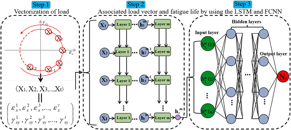
Figure 8. New method of lifetime prediction for multi-axial fatigue (Yang et al., 2021).
Although the above models have strong data generalization capability and predictive functionality, it is only through the construction of physics-informed data-driven prediction models that sample data can be combined with the mechanical and physical laws of corrosion fatigue. This integration enables more accurate predictions of corrosion fatigue life. Zhang X. C. et al. (2021), Dourado and Viana (2020), Kong et al. (2020), Chen and Liu (2022), and George et al. (2021) have conducted some research in this regard. However, due to the current limitations of such research, the application effectiveness of these models in corrosion fatigue remains to be objectively evaluated. Nevertheless, as an emerging approach for life prediction, this method offers prospects for development and application.
4 Corrosion fatigue experimental study on marine structures
Corrosion fatigue testing is an important research method for corrosion fatigue which can provide necessary data for verifying theoretical methods and models. Using the coupling level between fatigue load and the corrosion environment, corrosion fatigue testing can be divided into two types: load–environment interaction testing and load–environment coupling testing. We here provide an overview of the research progress on corrosion fatigue test and crack measurement methods related to marine steel structures and materials. In addition, the research status of the at-sea monitoring of corrosion fatigue damage in marine steel structures is also introduced.
4.1 Fatigue load–corrosion environment interaction test
Fatigue load–corrosion environment interaction testing examines the interaction of corrosion and fatigue on the structure or material according to a certain cycle period, also known as “pre-corrosion fatigue testing”.
Zhang and Zhang (2016) conducted a fatigue–corrosion interaction test on Q345 steel with different immersing–airing times which indicated that longer immersing–airing times lead to more corrosion and fatigue performance degradation. Guo et al. (2021a, 2022) conducted a fatigue test on Q690 high-strength steel after 60 and 100 days of corrosion and studied the influence of the degree of corrosion on the fatigue properties of Q690 high-strength steel. Only material specimens were used in the tests above tests, so they are only suitable for exploring the influence of corrosion on the fatigue properties and failure mechanism of materials but are not sufficient to reflect the fatigue properties of large-scale steel structures in corrosion environments. Zhang (2020) conducted a salt-spray corrosion test on the T tubular joint, widely used in marine engineering structures, at different periods in the salt spray cabin and then conducted a fatigue test on these corroded T tubular joints at room temperature under atmospheric conditions (Figure 9). Other studies on load–corrosion interaction testing are Shamir et al. (2023), Rangana et al. (2019), and Zhang A. Q.et al. (2022).
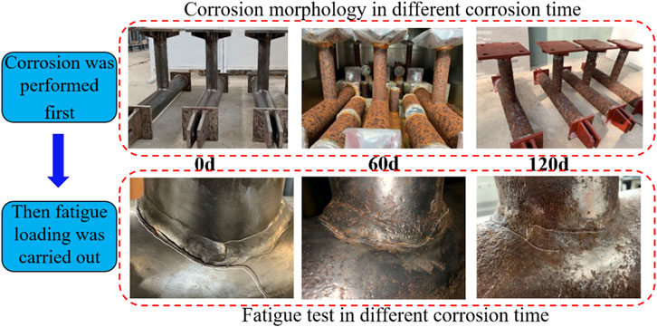
Figure 9. Pre-corrosion fatigue test of T tubular joint Zhang (2020).
Although the corrosion environment and fatigue load are considered separately in this method, it also has the following advantages.
(1) The requirements for both test equipment and technology will be reduced because to the corrosion environment and fatigue load are separate.
(2) It is hard to observe and detect the fatigue crack of steel structures in a corrosion environment. There is no corrosion environment in fatigue testing in this method, which can greatly reduce the difficulty of crack detection.
(3) This method is relatively economical, convenient, and feasible, and it is also practical due to the setting of a safety factor.
4.2 Fatigue load–corrosion environment coupling test
Fatigue load–corrosion environment coupling testing means that the structure or material specimen is subject to the combined action of fatigue load and the corrosion environment during the test. Setting an environmental box/container around the structure or material specimen is widely used in current tests. Different types of corrosion environment, such as salt spray and seawater, can be simulated in the environmental box/container, thereby realizing the coupling of the corrosion environment and fatigue load in the test. Typical corrosion fatigue test equipment with small a environment box is shown in Figure 10. The objects are mostly material specimens (such as standard tensile specimens, three-point bending specimens, etc.) for this test, and the monitoring/detection methods for fatigue life and cracks are also relatively mature. Current research mainly focuses on the influence of corrosion environment parameters (pH, salinity, temperature and humidity, etc.) and fatigue loading modes (load ratio, frequency, waveform, etc.) on the fatigue life, crack growth rate, and failure mechanism of specimens.
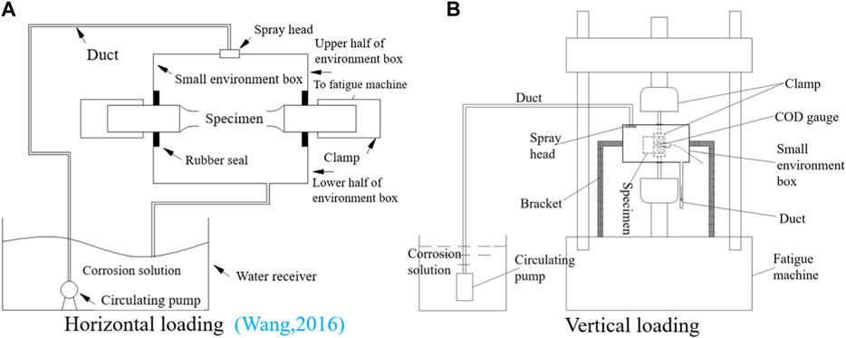
Figure 10. Typical corrosion fatigue test equipment with small environment box. (A) Horizontal loading (Wang, 2016). (B) Vertical loading.
Liu et al. (2022) conducted a corrosion fatigue test on three-point bending (TPB) specimens under the coupling of fatigue load and artificial seawater by using the external environmental box; they studied the influence of different fatigue loading modes (stress ratio and frequency) and different corrosion environmental conditions (temperature and flow velocity) on fatigue crack growth in specimens. Yang et al. (2023) made compact tensile (CT) specimens with a through-crack using Q420B steel and established a salt spray environment–fatigue load coupling test system by specimens, corrosion box, and frame style fatigue loading device (Figure 11) and then studied the impact of spraying mode, pH value, and stress ratio on the crack growth rate of the CT specimen. Zhang et al. (2019) conducted a corrosion fatigue test on 7,050-thick plate aluminum alloy material under 3.5% NaCl solution and oil tank water environment, respectively. They then analyzed the influence of different stress concentration factors and corrosion environments on the fatigue properties of this material by using the three-parameter fitting SN curve. Wang (2016) fabricated a tensile specimen using AH32 steel and designed the corrosion fatigue test equipment (Figure 10A) before conducting a pre-corrosion fatigue test and corrosion fatigue test on the tensile specimens. The result showed that the failure degree due to corrosion fatigue was much greater than that of pre-corrosion fatigue. Wang et al. (2019) conducted a crack-growth test on center cracked tension (CCT) specimens made of E690 steel in air and 3.5% NaCl solution under different stress ratios. Luo et al. (2021) established a marine atmospheric environment–tensile/compressive/bending load coupling test platform at Wanning test station in Hainan by using the outdoor humid/hot marine atmospheric environment as the corrosion environment (Figure 12). Although the test platform is mainly used to conduct corrosion fatigue testing on material specimens, it also provides application examples and ideas for corrosion fatigue testing. Liu et al. (2024) conducted fatigue tests on Q690D high-strength steel specimens under the coupling of fatigue loads and corrosive environments using the current-accelerated corrosion method and obtained the corrosion characteristics and SN curve of the specimens. Compared with non-corrosion and pre-corrosion, the corrosion fatigue life of the specimens decreased significantly. Other research on corrosion fatigue testing related to marine steel materials are reported in Cheng and Chen (2017a), Cheng and Chen (2017b), Wickmann and Sander (2023), and Yadav et al. (2023).
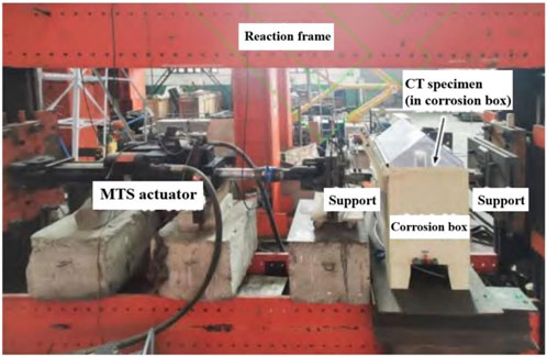
Figure 11. The coupling test system of salt spray environment and fatigue load (Yang et al., 2023).
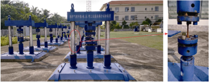
Figure 12. Coupling test platform of marine atmospheric environment and tensile/compression/bending load (Luo et al., 2021).
The fatigue load–corrosion environment coupling testing mentioned above is mainly aimed at the material or small standard specimen. Nevertheless, corrosion fatigue testing on full- or large-scale structural components can accurately reflect the anti-fatigue performance of marine steel structures in a corrosion environment. There is currently little research on the corrosion fatigue of full- or large-scale structural components. Chen et al. (2021) thus developed a corrosion fatigue test system suitable for large-scale models of marine engineering structures (Figure 13). This test system can provide the complex marine corrosion environmental parameters required in corrosion fatigue testing, including humidity, temperature, light, salt spray, flow velocity, seawater dissolved oxygen, and pH. The simulated corrosion environment in this system is closer to the real marine environment, and each environmental factor can also be dynamically adjusted according to the requirements of the corrosion acceleration rate. Real-time coupling between the marine corrosion environment and fatigue load is realized with a fatigue loading unit, breaking through the limits of corrosion fatigue testing on material specimens with the environmental small box. However, it still presents the following difficulties. 1) It is very difficult to monitor/detect the stress, strain, fatigue crack initiation, and growth of steel structures in harsh test environments such as high temperature and high humidity foggy environments and sea water environments. No appropriate means has yet been developed and applied. 2) It is difficult to conduct in-situ measurement of the corrosion rate/damage of large-scale structures due to their weight and the large area of corrosion anode. 3) There is no effective method of evaluating the coordination between corrosion damage and fatigue damage and of matching it with real sea conditions.
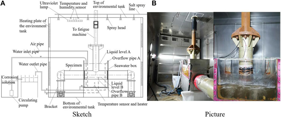
Figure 13. Sketch and picture of corrosion fatigue test system for large scale model (Chen et al., 2021). (A) Sketch. (B) Picture.
4.3 Accelerated corrosion methods in corrosion fatigue tests
Corrosion fatigue testing for marine structures should accurately replicate the load and corrosion damage conditions acting on the structure. Testing should also be accelerated to some degree in order to shorten the test time and save costs. The load condition can be defined and represented by the number of load cycles which drives the fatigue damage. Therefore, performing load acceleration (accelerated fatigue damage) is relatively simple and could be achieved by increasing the load frequency. On the other hand, it is difficult to realize short-term accelerated corrosion due to the corrosion damage mainly depending on the time.
At present, much research has been conducted on the marine atmospheric environment accelerated corrosion test, and many mature test methods have been established, such as salt spray testing (Cui et al., 2019; Wang H. J. et al., 2022; Peng et al., 2023), damp heat testing (Guo et al., 2021b), alternating dry–wet testing (Cheng et al., 2017), electrolytic accelerated corrosion testing (Chen et al., 2020), and Corrodkote accelerated corrosion testing (Feng et al., 2006). However, there is still no mature and standard method for seawater environment accelerated corrosion testing due to the significant difference between the seawater and marine atmospheric environments. Seawater is a natural electrolyte with complex composition; its temperature, salinity, dissolved oxygen concentration, acidity and alkalinity are all important factors that affect the corrosion rate of structural materials (Liu et al., 2003; Hou et al., 2016). Moreover, environmental conditions such as ocean current velocity and wave splash are also important influences on the corrosion rate (Yang et al., 2014). According to these characteristics of the seawater corrosion environment, the corrosiveness of a solution can usually be increased by adjusting the environmental parameters of the corrosive solutions to achieve the effect of accelerated corrosion in the current corrosion fatigue test. Woloszyk et al. (2021) conducted indoor accelerated corrosion research, developing an accelerated corrosion degradation device to simulate the degradation of marine structural samples at different levels of corrosion. The device controls the corrosion process by regulating factors such as temperature, PH, oxygen content, salinity, and flow rate. The corrosion degradation control experimental device exhibits good similarity in corrosion trends and acceleration. Khunphakdee and Chalermsinsuwan (2023) comprehensively reviewed the flow accelerated corrosion (FAC) mechanism and contributing factors, preventive measures, and FAC management strategies as well as FAC rate prediction models. The reduced intermediate product of O2, H2O2 can promote the seawater corrosion of low alloy steel under the condition of not changing the corrosion mechanism, and the effect of accelerated corrosion increases with increased H2O2 (Bai et al., 2024; Feng et al., 2024). In addition, Wang et al. (1987) proposed an accelerated wheel method and Yu et al. (2009) given an intermittent immersing corrosion test method. The principle of these two methods is to shorten the alternating dry–wet period and increase the contact time between the material and corrosion medium to achieve the effect of accelerated corrosion. However, the corrosion acceleration ratio (simulated corrosion rate–real sea corrosion rate) is still low in these accelerated corrosion tests. Therefore, it is difficult to achieve a high corrosion acceleration ratio (e.g. > 100) simply depending on adjusting the environmental parameters of corrosive solutions.
In comparison, the impressed-current accelerated corrosion (ICAC) technique is the most effective acceleration method and has been widely employed in laboratories to fabricate corroded steels within a relatively short time. Liu et al. (2024) conducted a corrosion fatigue test on Q690D high-strength steel specimens using the ICAC method; the set-up of this corrosion fatigue test is shown in Figure 14. However, the disparity between theoretical and actual mass losses, characterized as current efficiency, is difficult to quantitatively and nondestructively measure in ICAC (Hu et al., 2024). For this purpose, Hu et al. (2024) proposed and investigated a two-circuit setup along with a particular calculation method for measuring current efficiency without interrupting the ICAC current and destroying the steel samples.
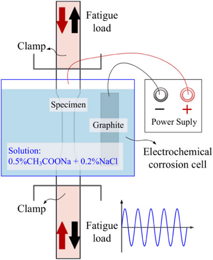
Figure 14. Set-up of corrosion fatigue test (Liu et al., 2024).
In addition, the ICAC technique is currently mainly employed in accelerated corrosion research and corrosion fatigue testing on material samples. Considering the safety of testing and the operability of the equipment’s insulation, it is difficult to apply the ICAC technique in corrosion fatigue testing on large-scale structures because the specimen, loading equipment, and corrosion device are so large. Furthermore, it is almost impossible to measure the corrosion rate of specimens in situ due to the difficulty of increasing the corrosion rate and the large corrosion area in corrosion fatigue testing on large-scale structures. It is also difficult to inflict obvious corrosion damage on the specimen in a short time due to the difficulty in increasing the corrosion rate. Thus, the corrosion damage of a specimen can only be increased by extending the test time, but this will significantly increase testing costs. Therefore, from the perspective of the development of corrosion fatigue test technology, simulating a high acceleration ratio corrosion environment is an important issue requiring further study.
4.4 Crack measurement methods
Crack measurement is an important aspect of corrosion fatigue testing; it can be divided into crack length and crack depth measurement. The former has been the subject of much research, and some mature methods have been formulated. Among these, crack length measurement methods based on the compliance principle, such as back face strain (BFS), crack tip opening displacement (CTOD), and unloading compliance have been widely used. The ratio between the deformation and the corresponding load of a material/specimen under external load is termed “compliance”. This will change as soon as cracks or crack growth occur in the material/specimen. A crack’s length can be calculated according to the change in compliance when other conditions remain unchanged (Chen, 2015). Therefore, the basic idea of the compliance method is to establish the conversion relationship between the dimensionless compliance D and the normalized crack length
Yang et al. (2023) obtained the crack length of CT specimens through the conversion relationship between BFS data and crack length (Eq. 23) by using the BFS method (Figure 15A). Wang et al. (2015) measured the crack length of CT specimens at room temperature under atmospheric conditions by using the CTOD and image observation methods. They found that the results of the two methods were basically consistent, further establishing the feasibility of this compliance method. Jacob and Mehmanparast (2021) measured the crack length of CT specimens under air and artificial seawater based on the BFS method and obtained good results. Chen (2015) studied the specific method of applying the BFS method to crack length measurement for TPB specimens and found that the strain and crack length had strong regularity on the front face of the sample and that the strain should be collected on the front face when using BFS (Figure 15B). Zhang H. J. et al. (2018) conducted fatigue crack growth testing on CT specimens of 16Mn steel submarine pipeline material at room temperature under atmospheric conditions based on the CTOD and BFS methods (Figure 16A). The result indicated that the two methods had good equivalency and were alternatives for each other. The crack length of the CT specimen was then measured by using the BFS method in seawater (Figure 16B).
where
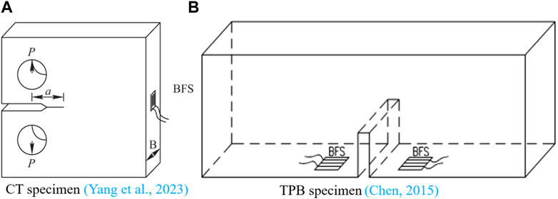
Figure 15. Sketch of Back Face Strain (BFS) method. (A) CT specimen (Yang et al., 2023). (B) TPB specimen (Chen, 2015).
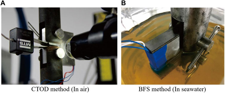
Figure 16. Measuring the crack length of CT specimen. (A) CTOD method (in air). (B) BFS method (in seawater).
In addition, digital image correlation (DIC) technology, the potentiometric method, the direct-reading method, and ultrasonic/magnetic particle/penetration detection methods can also be used to measure crack length. Zhang L. et al. (2022) proposed crack length detection based on digital images. Firstly, the noise interference on the structural surface is eliminated using a convolutional neural network and identifying the crack characteristics. Then, the exact coordinates of the crack tip are obtained using the crack tip identification algorithm and reading the crack length according to the coordinates.
Huang et al. (2022) proposed a high-precision dynamic method to measure fatigue crack length based on the combination of edge detection and DIC technology, with the aim of detecting the crack length caused by its closure. Compared with the edge detection and microscope direct-reading methods, the results indicated that this method had significant advantages in measurement accuracy and can effectively detect the closed crack. To solve the problem of measuring the crack length of aero-engine materials at high temperature (650 °C∼800 °C), Wang L. et al. (2022) proposed that the direct current potential method can be applied to measure the crack length of a GH4169 superalloy material CCT specimen, and the feasibility and effectiveness of this method have been verified by experiments. Wang et al. (2021) proposed a crack length measurement method combining fluorescence penetration detection and pixel size accumulation processing for the crack image, so as to measure and calculate the crack length on the complex surface of a workpiece. Zhang et al. (2016) introduced a surface crack length measurement method by using the crack expander developed from the direct current potential method. This method was simple to operate and had high accuracy, and it can measure surface crack length automatically. Li et al. (2015) proposed a measuring device for fatigue crack length based on the alternating current potential method. This measuring device is based on the LabVIEW platform, and it adopted a virtual instrument system to collect, analyze, and process data, and realized functions such as visual operation, automatic measurement, curve display, and data preservation.
These methods have been widely used for crack length measurement in conventional test environments, but have rarely been used in harsh corrosive environments such as high temperature, high humidity, high salt spray, and seawater.
On the other hand, the main task for surface cracks is to measure the crack depth, which has been the subject of much research. The alternating current potential drop (ACPD) method had been used earlier in the measurement of surface crack depth. This technique detects crack size in steel structures based on the theory of alternating current (AC) potential drop (Shao, 2010). A skin effect will be produced as the high frequency AC flows through ferromagnetic materials, making the current flow only within a certain thickness range of the surface layer of a metal (steel) structure. As shown in Figure 17, the current passes through a path with surface crack ΔR as the probe spacing, and ΔC = ΔR as the surface spacing containing the crack. The potential drop corresponding to ΔR is VR, the potential drop corresponding to ΔC is VC, and d1 is the crack depth. The potential drop is proportional to the distance the current passes.
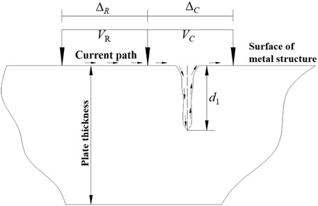
Figure 17. Sketch of measuring surface crack using the ACPD method.
The crack depth (Eq. 26) can be derived from Eqs 24, 25:
Theoretically, the ACPD method applies only to an infinitely long crack in an infinitely large plate. It is not suitable for detecting the surface crack of most engineering structures (such as tubular joints), but it can be corrected to achieve the desired effect. Shao (2010) and Shao et al. (2013) conducted fatigue crack growth tests on welded K- and T-type tubular joints at room temperature under atmospheric conditions, measuring the crack depth and length during surface crack growth based on ACPD. Compared with the measured crack shape, the measured value using the ACPD agrees well with the actual value at the crack deepest point, while the measured value, at some parts deviating from the deepest point, has a large error. Chaudhuri et al. (2019) established a multi-probe ACPD device to monitor crack initiation at the weld toe by laying working and reference probes on one side of a cross welded joint (Figure 18) and defined the moment when the potential decline of the working probe was 2 mV at the moment of crack initiation. The device can monitor crack initiation at the weld toe well, but the multiple cracks at the weld toe will affect the recognition of ACPD signal, leading to the measurement error. Therefore, measurement accuracy using the ACPD method is closely related to the shape and distribution of cracks (multi-crack, oblique crack, shallow-short crack, deep crack, etc.) on the measured surface. In practical application, it is necessary to correct the measured value according to the specific situation. Chen et al. (2022) proposed a method combining strain monitoring, ACPD, and fatigue scoring to provide corresponding measurement according to different stages of surface crack (such as initiation stage, stable growth stage, instability/rapid growth stage). It thus achieved full coverage tracking measurement of surface crack initiation and the growth process of steel structures. However, there are still limitations in their application to corrosion environments.
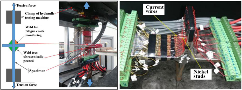
Figure 18. Measuring the surface crack of cross-welded joint using the ACPD method (Chaudhuri et al., 2019).
In addition, eddy current testing, AC/DC magnetic flux leakage testing, and alternating current field measurement (ACFM) are also suitable for surface crack detection. ACFM is based on the principle of electromagnetic induction and can be applied in both conventional and corrosion environments. It has the advantages of non-contact detection and has no need to clean corrosion products and coatings on the surface of the structure. It shows good prospects for application in the surface crack detection of marine steel structures. As shown in Figure 19, when a special coil (excitation coil) with AC is close to the tested specimen (conductor), the AC will generate an alternating magnetic field in the surrounding space, and the induced current in the specimen will accumulate on the surface due to skin effect. The induced current lines are parallel when there is no crack in the specimen. If there is a crack, its resistivity will change and affect the current distribution. The current line will be deflected near the crack, thereby distorting the magnetic field on the specimen surface. The crack size can then be revealed by detecting the change in magnetic field strength.
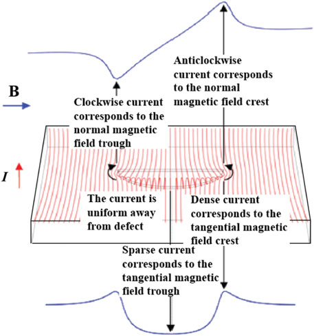
Figure 19. Principle of ACFM (Jia et al., 2021).
Jia et al. (2021) proposed an array-based ACFM detection system that can be used for underwater structural crack detection and developed hardware, software and a detection prototype correspondingly. The underwater detection test in the laboratory and on the No. 3 drilling platform of the China National Offshore Oil Corporation (CNOOC) validate that this detection system had good real-time performance and stability; the recognition ability of complex cracks/defects reached 10 mm. Li et al. (2023) combined the advantages of AC magnetic flux leakage testing and ACFM on their respective sensitivity to transverse and longitudinal cracks and proposed a detection method for steel plate surface crack depth based on balanced electromagnetic technology to realize the quantitative detection of transverse and longitudinal crack depth on steel plate surface. Zhao et al. (2022) studied the influence of ACFM detection probe lifting on magnetic field response signal, improved and developed a ACFM calculation model insensitive to probe lifting, and established a detection system for testing. The results showed that the influence of the probe lifting distance on the surface crack depth and length were greatly improved by using the improved model and detection system.
Although ACFM has become one of the most advantageous underwater structure detection technologies due to its non-contact detection and sensitivity to cracks, it is found in practical application that ACFM exhibits good detection only on cracks with a single direction and simple shape, while it is difficult to detect complex cracks, such as oblique, bifurcation, dense, and star cracks. These problems need further study.
The crack measurement methods mentioned above and their advantages and disadvantages are summarized and compared in Table 1.
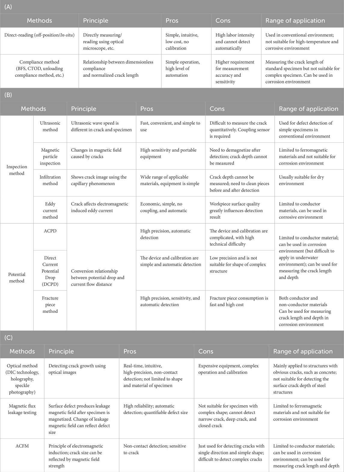
Table 1. Comparison of crack measurement methods.
4.5 At-sea monitoring of corrosion fatigue damage
Currently, the issue of aging marine engineering equipment is severe, and there are many marine platforms that have exceeded their service life but are still in use, posing significant structural safety risks (Li, 2022). Corrosion fatigue damage is the primary form of damage faced by in-service marine steel structures, and it is of great significance to analyze and assess them using at-sea monitoring methods. As shown in Figure 20, the monitoring system for marine platforms can include sub-systems such as marine environmental monitoring, platform motion monitoring, and structure and mooring system monitoring (Zhu et al., 2022).
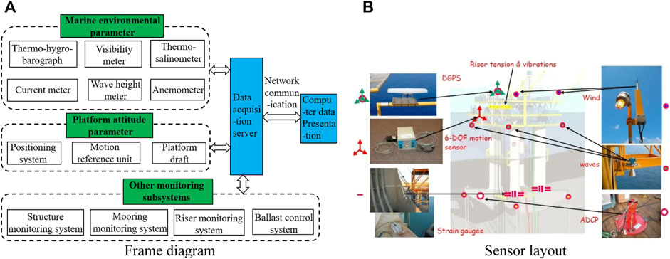
Figure 20. Integrated monitoring system for marine platform (Zhu et al., 2022). (A) Frame diagram. (B) Sensor layout.
A summary of the main structural damage monitoring techniques is presented in Table 2. Feng (2021) proposed a damage diagnostic method that combines curvature and strain modes based on the modal analysis method in the global damage detection approach, which can locate and quantitatively estimate circumferential through-cracks in structures. Ge (2020) used a single-sided notched specimen as an example and proposed a method for the real-time monitoring of structural fatigue damage by using piezoelectric ceramic fiber sensors to determine the stress intensity factor during fatigue crack growth. In recent years, the application of fiber optic grating sensors for the at-sea monitoring of marine steel structures has been rapidly developed. Li (2022) designed a crack monitoring sensor with good linearity and stability based on the encapsulation principle of fiber optic grating sensors and conducted practical measurements on an aging jacket platform.
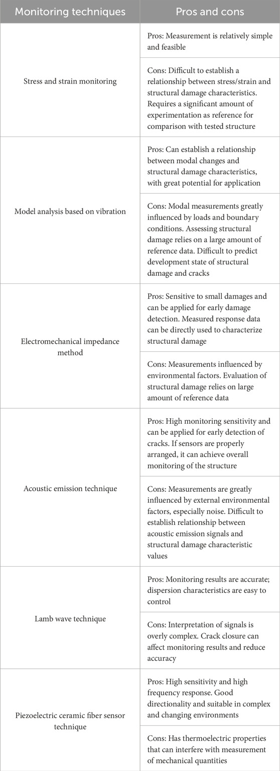
Table 2. Technique for structural damage monitoring.
Techniques have emerged in recent years for the at-sea detection of local structural damage. For example, crack/defect detection based on ACFM has many advantages, such as insensitivity to lift-off, non-contact detection, and quantitative measurement (Yuan et al., 2020) (Figure 21). This detection system can be carried out by underwater robots to quantitatively detect cracks/defects in underwater steel structures. Additionally, the flooded member detection (FMD) technique is a unique underwater detection method for structural damage, suitable for detecting through-crack or other defects that allow water to infiltrate the component’s interior.
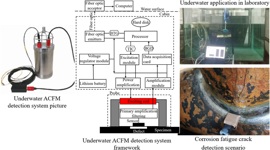
Figure 21. ACFM detection system and application scenarios (Yuan et al., 2020).
Although local damage detection methods can accurately identify structural damage, they cannot provide real-time monitoring of the structural damage condition. Additionally, despite extensive research on marine structural damage monitoring systems, there are still limitations in their application to in-service marine platforms and other at-sea scenarios. In general, the following issues require further research: 1) errors in monitoring signal identification caused by service environment and testing conditions; 2) nonlinearity of materials and structures during service, leading to monitoring errors; 3) incomplete structural mode monitoring, including incomplete degrees of freedom and mode orders, affecting structural damage analysis; 4) due to the incompleteness of the aforementioned modes, the monitoring system must rely on low-order mode information of the structure for damage assessment, which is challenging to obtain for marine platform structures.
5 Corrosion fatigue life assessment for marine structures in the whole life period
Marine structures in service suffer from the combined action of corrosion damage and fatigue damage. As service life increases, the fatigue resistance of the structure decreases and the risk of structural failure rises. A proportion of currently operational marine platforms have entered the stage of exceeding their design service life, and fatigue damage such as cracks have been discovered in some platforms. Therefore, paying attention to the corrosion fatigue of marine structures in the whole life period is of great engineering and practical significance for evaluating and analyzing the safety, remaining life, and extension margin benefits of these structures.
Nowadays, the methods used for evaluating fatigue life in marine platform structures mainly include fatigue damage assessment based on linear cumulative damage theory and SN curves, and crack growth assessment based on fracture mechanics theory.
Many scholars have conducted extensive research on the pure fatigue (non-corrosion fatigue) of various marine platform structures based on these two assessment methods. Xu S. X. et al. (2023) provided a distribution formula for the bending curvature along the intersection line between the brace and chord of a tubular joint with a crack in the jacket platform based on the net section failure criterion. They evaluated the crack growth in the tubular joints of a jacket platform in the South China Sea by using the assessment procedure and failure assessment diagram (FAD) issued by the British Standards Institution BS7910, thereby verifying the accuracy of the bending curvature distribution formula for fatigue crack assessment in tubular joints. Yin and Yi (2022) established an engineering critical assessment (ECA) method for crack growth assessment in marine platform structures based on the Paris formula and FAD. They conducted a crack growth assessment using a critical structure of a semi-submersible platform as an example. Sang et al. (2020) focused on the OC4 semi-submersible floating wind turbine foundation and calculated the fatigue damage in seven critical locations of the structure under the combined action of wind and waves based on the linear cumulative damage theory and SN curves. Similar research can be found in Tao (2020), Zhao (2018), Saadian and Taheri (2018), Zhang (2018), and He et al. (2022).
Clearly, to only consider the fatigue damage caused by fatigue loads cannot accurately reflect the fatigue life of platform structures during service. However, due to the complexity of corrosion fatigue in marine platforms (coupling of complex service environments and random wave loads), there is currently little research on the corrosion fatigue of platform structures in the whole life period. Yu (2013) established a corrosion model for marine engineering structural steel that considers the influence of mechanical factors based on corrosion kinetics theory, which was used to modify the finite element model of marine platform structures at different service times. The fatigue life of platform structures was evaluated based on the linear cumulative damage theory and the SN curve in corrosion environments. Tran Nguyen et al. (2013) modified the section modulus of ship structures by using the corrosion model obtained from at-sea corrosion tests and calculated the fatigue damage of ship structures based on the linear cumulative damage theory. Wang J. C. et al. (2023) developed a frequency domain fatigue analysis model for a jacket platform and analyzed the influence of different SN curves and corrosion models on the structure fatigue life based on the linear cumulative damage theory. However, in fatigue assessment, the effect of corrosion is only considered by reducing the plate thickness of structures.
Kim (2021) obtained the corrosion rates of plate thickness at different corrosion times based on the corrosion model of marine platform structure materials in the immersion zone. The effective stress range and stress intensity factor range of the structure after thickness corrosion deduction were calculated using the Müller and Newman–Raju equations, respectively. Then, the crack growth life of the structure under various corrosion times was predicted using the Paris formula. Zhao et al. (2019) studied the crack growth characteristics of the intersection between the columns and braces of a semi-submersible platform under the action of random wave loads. Crack growth was investigated under the condition of original plate thickness and plate thickness corrosion deduction after 20 years of service based on the Paris formula and FAD. The results showed that fatigue crack growth life decreased approximately 30% under the condition of plate thickness deduction, while the critical parameters of the crack, such as critical crack depth/width, critical fracture ratio, and critical stress ratio, did not change significantly.
Similar to the above studies, Kim (2021) and Zhao et al. (2019) only considered the influence of corrosion on fatigue crack growth based on the method of thickness corrosion deduction. In fact, when considering the impact of corrosion damage on the fatigue life of platform structures, in addition to considering thickness corrosion deduction, the degradation of material properties should also be given great attention. Yang et al. (2020) evaluated and predicted the corrosion fatigue life of tubular joints in a jacket platform based on the linear cumulative damage theory and the SN curves in a corrosion environment. The evaluation considered the plate thickness reduction and material property degradation caused by corrosion during the platform’s service period and adjusted the finite element model of the structure based on the remaining plate thickness and real-time mechanical performance parameters at different corrosion times. The results showed that both plate thickness reduction and material property degradation would shorten the structure’s fatigue life, and the fatigue life of certain tubular joints in the splash zone would be reduced 50%–60%.
In summary, the current research on corrosion fatigue for marine structures in the whole-life period is not yet sufficiently deep. There are still several issues that need further research:
(1) The accuracy of corrosion fatigue damage assessment based on linear cumulative damage theory relies on the selection of SN curves in the corrosion environment. However, the SN curve parameters provided by various standards or research differ significantly, and there is no unified SN curve available for assessing the corrosion fatigue damage of marine structures.
(2) Similarly, when conducting corrosion fatigue crack growth assessment based on fracture mechanics, the crack growth parameters in the generalized Paris formula need to be determined experimentally and exhibit strong material–environment dependency. Currently, there is no unified and mature set of crack growth parameters available for assessment.
(3) In the existing corrosion fatigue assessment methods, corrosion and fatigue are still considered separately, and the mutual interaction between the two has not been adequately considered.
(4) The theoretical and experimental research on the corrosion fatigue of material specimens/structural components mentioned earlier still faces unresolved challenges, making it difficult to popularize and apply the research findings to the corrosion fatigue assessment of marine structures in their whole life period.
6 Conclusion and recommendations
To date, there has been much experimental and theoretical research on the corrosion fatigue of marine structures and materials. Some theoretical models and methods for predicting the corrosion fatigue life of metallic materials or structures have been proposed and applied successively. Load–environment interaction/coupling testing on the metallic material specimens has been maturely developed and widely applied. In addition, some newly-developed corrosion fatigue theoretical and experimental methods, based on data-driven/machine learning and at-sea monitoring, have been preliminarily applied. However, current corrosion fatigue life prediction theoretical models and methods still involve a significant amount of simplification and assumptions. The model parameters are also complex, making it difficult to popularize and apply the research findings to corrosion fatigue assessment for marine structures in the whole life period. Quantifying the acceleration of fatigue damage caused by corrosive environments and understanding the synergistic relationship between them still remains an unresolved technical challenge. Moreover, although newly developing methods based on data-driven/machine learning have been introduced in corrosion fatigue assessment, the scientific problem between corrosion and fatigue has essentially not been resolved.
In terms of corrosion fatigue testing, current tests are mainly aimed at the material or small standard specimen, and there are currently few tests designed for the structural member. It is very difficult to monitor/detect the stress, strain, and fatigue crack initiation and growth of steel structures in harsh test environments such as high temperature/high humidity/high salt spray environments and sea water environments. Expanding the model test at-sea, accurately monitoring structural fatigue damage characteristics (such as crack size, structural mode, and structural stress and strain) in the marine environment, and establishing corresponding fatigue life prediction methods are still challenges requiring further study.
In conclusion, the future developments and suggestions related to corrosion fatigue in marine structures are:
(1) Dynamic corrosion damage factors and corresponding dynamic evaluation mechanisms should be introduced into the corrosion fatigue life prediction theoretical models, as well as quantifying the synergistic/coupling relationship between corrosion and fatigue and establishing a corrosion fatigue life prediction model that is more in line with the actual situation and is easy to popularize.
(2) Establishing physics-informed data-driven prediction models and methods by introducing physical laws into machine learning based on current data-driven prediction models.
(3) Breaking through the limitation of test conditions and developing load-environment coupling testing for large-scale structural members; studying the representation and testing methods on the stress, strain, and fatigue crack initiation and growth of steel structures in the harsh test environments; enhancing the simulation and acceleration ratio of indoor corrosion testing; developing corrosion rate in-situ measurement of large-scale structural members.
(4) Device, sensor, and signal processing methods which can accurately monitor structural fatigue damage characteristics should be further developed and studied, thereby improving the reliability of at-sea monitoring data and fatigue life assessment.
(5) Corrosion fatigue assessment methods for marine structures in the whole life period that effectively consider the coupling effect of corrosion and fatigue also need further development.
Author contributions
YY: Conceptualization, Data curation, Formal Analysis, Investigation, Methodology, Resources, Visualization, Writing–original draft, Writing–review and editing. CC: Conceptualization, Funding acquisition, Methodology, Project administration, Supervision, Writing–review and editing. YZ: Data curation, Formal Analysis, Investigation, Resources, Writing–original draft. ZS: Data curation, Formal Analysis, Investigation, Resources, Visualization, Writing–review and editing.
Funding
The authors declare that financial support was received for the research, authorship, and/or publication of this article. This study was financially supported by the National Natural Science Foundation of China (Grant No. 51979111), the Key R&D Program of Guangdong Province, China (Grant No. 2020B1111010001), and the New Energy Joint Laboratory Open Research Fund Project of China Southern Power Grid (Grant No. 0304002022032103GD00036).
Conflict of interest
The authors declare that the research was conducted in the absence of any commercial or financial relationships that could be construed as a potential conflict of interest.
The reviewer PH declared a shared affiliation with the authors to the handling editor at the time of review.
Publisher’s note
All claims expressed in this article are solely those of the authors and do not necessarily represent those of their affiliated organizations, or those of the publisher, the editors and the reviewers. Any product that may be evaluated in this article, or claim that may be made by its manufacturer, is not guaranteed or endorsed by the publisher.
References
Akid, R. (1996). “The role of stress-assisted localized corrosion in the development of short fatigue cracks,” in Proceedings of symposium on effects of the environment on the initiation of crack (Orlando, Florida: Amer Society Testing and Materials).
Bai, X. H., Ding, K. K., Zhang, P. H., Fan, L., Zhang, H. X., Liu, S. T., et al. (2024). Accelerated corrosion test of AH36 ship hull steel in marine environment. J. Chin. Soc. Corros. Prot. 44 (01), 187–196. doi:10.11902/1005.4537.2023.053
Cavanaugh, M. K., Buchheit, R. G., and Birbilis, N. (2010). Modeling the environmental dependence of pit growth using neural network approaches. Corros. Sci. 52 (9), 3070–3077. doi:10.1016/j.corsci.2010.05.027
Chaudhuri, S., Crump, J., Reedl, P. A. S., and Mellor, B. G. (2019). High-resolution 3D weld toe stress analysis and ACPD method for weld toe fatigue crack initiation. Weld. World 63, 1787–1800. doi:10.1007/s40194-019-00792-3
Chen, C. H., Yang, Y. F., Li, P., and Pang, G. L. (2021). Corrosion fatigue test system and method for large scale model of ocean engineering structures. Chinese patent. CN112924369A.
Chen, C. H., Yang, Y. F., Ma, Y. L., Pang, J. J., Zhuang, Y. F., and Li, P. (2022). A detection method for surface crack initiation and propagation of steel structures. Chinese patent. CN115267123A.
Chen, J., and Liu, Y. M. (2022). Fatigue modeling using neural networks: a comprehensive review. Fatigue & Fract. Eng. Mater. Struct. 45 (4), 945–979. doi:10.1111/ffe.13640
Chen, J. W., Fu, C. Q., Ye, H. L., and Jin, X. (2020). Corrosion of steel embedded in mortar and concrete under different electrolytic accelerated corrosion methods. Constr. Build. Mater. 241, 117971. doi:10.1016/j.conbuildmat.2019.117971
Chen, T. (2016). Study on corrosion fatigue crack growth of D36 steel in seawater. Master's thesis. Dalian, China: Dalian University of Technology.
Chen, Y. Q. (2015). Experimental research on crack length measurement method of three points bending specimen. Master's thesis. Dalian, China: Dalian University of Technology.
Cheng, A. K., and Chen, N. Z. (2017a). Corrosion fatigue crack growth modelling for subsea pipeline steels. Eng. Fail. Anal. 142, 10–19. doi:10.1016/j.oceaneng.2017.06.057
Cheng, A. K., and Chen, N. Z. (2017b). Fatigue crack growth modelling for pipeline carbon steels under gaseous hydrogen conditions. Int. J. Fatigue 96, 152–161. doi:10.1016/j.ijfatigue.2016.11.029
Cheng, C. Q., Klinkenberg, L., Ise, Y., Zhao, J., Tada, E., and Nishikata, A. (2017). Pitting corrosion of sensitised type 304 stainless steel under wet–dry cycling condition. Corros. Sci. 18, 217–226. doi:10.1016/j.corsci.2017.02.010
Co, N. E. C., Brown, D. E., and Burns, J. T. (2018). Data-science analysis of the macro-scale features governing the corrosion to crack transition in AA7050-T7451. JOM 70 (7), 1168–1174. doi:10.1007/s11837-018-2864-6
Cui, C. J., Chen, A. R., and Ma, R. J. (2020). An improved continuum damage mechanics model for evaluating corrosion fatigue life of high strength steel wires in the real service environment. Int. J. Fatigue 135, 105540. doi:10.1016/j.ijfatigue.2020.105540
Cui, C. J., Ma, R. J., Chen, A. R., Pan, Z., and Tian, H. (2019). Experimental study and 3D cellular automata simulation of corrosion pits on Q345 steel surface under salt-spray environment. Corros. Sci. 154, 80–89. doi:10.1016/j.corsci.2019.03.011
Dourado, A., and Viana, F. A. C. (2020). Physics-informed neural networks for missing physics estimation in cumulative damage models: a case study in corrosion fatigue. J. Comput. Inf. Sci. Eng. 20 (6), 061007. doi:10.1115/1.4047173
Ebara, R. (2006). Corrosion fatigue phenomena learned from failure analysis. Eng. Fail. Anal. 13, 516–525. doi:10.1016/j.engfailanal.2004.12.024
Feng, L., Zheng, J. Q., Guo, Z., and Cui, Z. (2024). Experimental study on the mechanical properties and ultimate strength of accelerated corrosion on hull plates. Mar. Struct. 95, 103591. doi:10.1016/j.marstruc.2024.103591
Feng, L. T., Liu, Q., Bao, X., and Feng, S. B. (2006). Investigation on porous oxygen electrode of bronze ware accelerated corrosion. J. Chin. Soc. Corros. Prot. 26, 184. doi:10.3969/j.issn.1005-4537.2006.03.012
Feng, S. D. (2021). Research on damage diagnosis of jacket offshore platform based on modal analysis. Master's thesis. Harbin, China: Harbin Institute of Technology.
Ge, R. F. (2020). MFC-based stress intensity factor monitoring and fatigue life assessment of damaged structure. Master's thesis. Harbin, China: Harbin Institute of Technology.
George, E. K., Yannis, K., Lu, L., Perdikaris, P., Wang, S., and Yang, L. (2021). Physics-informed machine learning. Nat. Rev. Phys. 3 (6), 422–440. doi:10.1038/s42254-021-00314-5
Goswami, T. K., and Hoeppner, D. W. (1995). Pitting corrosion fatigue of structural materials. New York: ASME.
Guo, H. C., Cai, X. Y., Li, G. Q., Wang, Y. B., and Liu, Y. H. (2022). Fatigue performance of butt welds of high strength steel under the humid and hot immersion environment. J. Build. Mater. 25 (8), 823–829. doi:10.3969/j.issn.1007-9629.2022.08.008
Guo, H. C., Wei, H. H., Li, G. Q., and Sun, F. (2021b). Experimental research on fatigue performance of butt welds of corroded Q690 high strength steel. J. Constr. Steel Res. 184, 106801. doi:10.1016/j.jcsr.2021.106801
Guo, H. C., Wei, H. H., Yang, D. X., Liu, Y. H., Wang, Z. S., and Tian, J. B. (2021a). Experimental research on fatigue performance of Q690 high strength steel in marine corrosive environment. China Civ. Eng. J. 54 (5), 36–45. doi:10.15951/j.tmgcxb.2021.05.004
Harlow, D. G., and Wei, R. P. (1994). Probability approach for prediction of corrosion and corrosion fatigue life. AIAA J. 32 (10), 2073–2079. doi:10.2514/3.12254
He, W. T., Xie, L. J., Wang, S. Q., Wang, C., Hu, Z., and Liu, J. (2022). Fatigue characterization analysis of a submerged fishing farm platform through spectral-based fracture mechanics. Ocean. Eng. 264, 112351. doi:10.1016/j.oceaneng.2022.112351
Hou, B. R., Zhang, D., and Wang, P. (2016). Marine corrosion and protection: current status and prospect. Bull. Chin. Acad. Sci. 31 (12), 1326–1331. doi:10.16418/j.issn.1000-3045.2016.12.006
Hu, J. Y., Liu, Y. J., Dong, Z., and Zhang, S. (2024). A novel method to measure the actual corrosion resistance/rate of steel reinforcement during impressed-current accelerated corrosion test. Constr. Build. Mater. 426, 136060. doi:10.1016/j.conbuildmat.2024.136060
Huang, X. G. (2013) “Mechanism study of pit Evolution and crack propagation for corrosion fatigue,” in Doctoral thesis. Shanghai, China: Shanghai Jiaotong University.
Huang, X. G., and Wang, L. M. (2016). Pit evolution and crack nucleation mechanism study of corrosion fatigue. J. Ship Mech. 20 (8), 992–998. doi:10.3969/j.issn.1007-7294.2016.08.008
Huang, X. W., Shan, X. F., Gao, H. L., and Wang, C. (2022). Fatigue crack length measurement method based on edge detection and DIC. Acta Armamentarii 43 (04), 940–951. doi:10.12382/bgxb.2021.0268
Jacob, A., and Mehmanparast, A. (2021). Crack growth direction effects on corrosion-fatigue behaviour of offshore wind turbine steel weldments. Mar. Struct. 75, 102881. doi:10.1016/j.marstruc.2020.102881
Jia, D., Ding, T. H., Luo, X. L., Jin, Y., Zhang, Y., Wang, Y. C., et al. (2021). Design and implementation of a prototype of underwater array ACFM inspection system. Foreign Electron. Meas. Technol. 40 (04), 150–157. doi:10.19652/j.cnki.femt.2002472
Khunphakdee, P., and Chalermsinsuwan, B. (2023). Review of flow accelerated corrosion mechanism, numerical analysis, and control measures. Chem. Eng. Res. Des. 197, 519–535. doi:10.1016/j.cherd.2023.08.012
Kim, W. B. (2021). “Evaluation of long-term corrosion fatigue life of ship and offshore structural steel,” in Practical design of ships and other floating structures-proceedings of the 14th international symposium (Singapore), 505–516.
Kondo, Y. (1989). Prediction of fatigue crack initiation life based on pit growth. Corrosion 45 (1), 7–11. doi:10.5006/1.3577891
Kong, H. B., Jo, S. H., Jung, J. H., Ha, J. M., Shin, Y. C., Yoon, H., et al. (2020). A hybrid approach of data-driven and physics-based methods for estimation and prediction of fatigue crack growth. Int. J. Prognostics Health Manag. 11 (1), 1–12. doi:10.36001/ijphm.2020.v11i1.2605
Li, J. Y., Yang, L. J., and Zheng, W. X. (2023). Surface crack depth detection method for steel plates based on balanced-field electromagnetic technique. Instrum. Tech. Sens. 482 (03), 104–109. doi:10.3969/j.issn.1002-1841.2023.03.018
Li, S. X., and Akid, R. (2013). Corrosion fatigue life prediction of a steel shaft material in seawater. Eng. Fail. Anal. 34, 324–334. doi:10.1016/j.engfailanal.2013.08.004
Li, X. Y., Han, Z. D., Ran, G., and Wang, B. F. (2015). Measurement method and equipment of fatigue crack length based on alternating potential method. Phys. Test. Chem. Analysis Part A Phys. Test. 51 (08), 542–545+559. doi:10.11973/lhjy-wl201508004
Li, Y. T. (2022). Design and verification of multi-scale crack monitoring method for offshore platform. Master's thesis. Dalian, China: Dalian University of Technology.
Liu, D., Liu, J., Huang, F., and Du, L. Y. (2022). Corrosion fatigue crack propagation performance of DH36 steel in simulated service conditions for offshore engineering structures. J. Chin. Soc. Corros. Prot. 42 (6), 959–965. doi:10.11902/1005.4537.2021.336
Liu, D. Y., Wei, K. J., Li, W. J., and Cao, F. Y. (2003). Influence of environmental factors in Yulin area of the south China sea on localized corrosion of steels. J. Chin. Soc. Corros. Prot. 4, 20–25. doi:10.3969/j.issn.1005-4537.2003.04.005
Liu, H., Zan, C. W., and Zong, L. (2024). Corrosion fatigue behaviour of Q690D high-strength steel considering the effect of coupling. Int. J. Fatigue 183, 108243. doi:10.1016/j.ijfatigue.2024.108243
Lou, L. Z., Zhou, K., Li, X. F., and Fu, Z. X. (2021). Corrosion damage behavior of 30CrMnSiNi2A steel under coupling action of marine atmospheric environment and tensile fatigue load. Surf. Technol. 50 (8), 349–358. doi:10.16490/j.cnki.issn.1001-3660.2021.08.034
Mao, M. D., Zhang, X. C., Tu, S. T., and Xuan, F. (2014). Prediction of crack initiation life due to corrosion pits. J. Aircr. 51 (3), 805–810. doi:10.2514/1.c032436
Miao, Y. Y., and Lv, S. L. (2019). Micromechanics-based modeling of pitting corrosion damage in aero aluminum alloy. Chin. J. Solid Mech. 40 (2), 137–146. doi:10.19636/j.cnki.cjsm42-1250/o3.2018.045
Nam, T. H., Kwon, M. S., and Kim, J. G. (2015). Mechanism of corrosion fatigue cracking of automotive coil spring steel. Metals Mater. Int. 21 (6), 1023–1030. doi:10.1007/s12540-015-5326-5
Peng, Y. W., Zhao, J. W., Liu, Y. F., Han, R., Liu, Z., and Gao, J. (2023). Galvanic corrosion between Al-Zn-Mg-Cu alloy and stainless steel in the salt-spray atmosphere. Mater. Chem. Phys. 294, 127009. doi:10.1016/j.matchemphys.2022.127009
Pidaparti, R. M. (2007). Structural corrosion health assessment using computational intelligence methods. Struct. Health Monit. 6 (3), 245–259. doi:10.1177/1475921707081975
Rangana, D. M. P., Bandara, H. M. L. S., and Abeygunawardane, G. A. (2019). Effect of corrosion surface topography on fatigue life of low-carbon steel. Moratuwa Eng. Res. Conf., 599–604. doi:10.1109/MERCon.2019.8818808
Saadian, R., and Taheri, A. (2018). Fatigue damage analysis of an existing fixed offshore platform using spectral method for life extension. J. Mar. Sci. Technol. 23, 877–887. doi:10.1007/s00773-017-0517-z
Sadananda, K., and Vasudevan, A. K. (2020). Analysis of pit to crack transition under corrosion fatigue & the safe-life approach using the modified Kitagawa-Takahashi diagram. Int. J. fatigue 134, 105471. doi:10.1016/j.ijfatigue.2020.105471
Sang, S., Dong, J. Q., Cao, A. X., and Dong, Z. (2020). Fatigue strength assessment of semi-submersible floating wind turbine foundation under turbulent wind. Acta Energiae Solaris Sin. 41 (7), 327–333. doi:10.32732/jcec.2018.7.1.27
Shamir, M., Braithwaite, J., and Mehmanparast, A. (2023). Fatigue life assessment of offshore wind support structures in the presence of corrosion pits. Mar. Struct. 92, 103505. doi:10.1016/j.marstruc.2023.103505
Shao, Y. B. (2010). “Measuring crack propagation of welded tubular joints by using ACPD technique,” in Symposium of the 12th China steel association structural stability and fatigue branch (China: Ningbo), 571–576.
Shao, Y. B., Song, S. Z., and Li, T. (2013). Study on safety of circular tubular T-joints containing fatigue crack based on failure assessment diagram. Eng. Mech. 30 (09), 184–193. doi:10.6052/j.issn.1000-4750.2012.05.0358
Shi, P., and Mahadevan, S. (2001). Damage tolerance approach for probabilistic pitting corrosion fatigue life prediction. Eng. Fract. Mech. 68 (13), 1493–1507. doi:10.1016/s0013-7944(01)00041-8
Sriraman, M. R., and Pidaparti, R. M. (2010). Crack initiation life of materials under combined pitting corrosion and cyclic loading. J. Mater. Eng. Perform. 19 (1), 7–12. doi:10.1007/s11665-009-9379-9
Tao, J. (2020). Study on fatigue life of Jack-up platform pile leg based on S-N curve and fracture mechanics. Daqing, China: Northeast Petroleum University. Master's thesis.
Tran Nguyen, K., Garbatov, Y., and Guedes Soares, C. (2013). Spectral fatigue damage assessment of tanker deck structural detail subjected to time-dependent corrosion. Int. J. Fatigue 48, 147–155. doi:10.1016/j.ijfatigue.2012.10.014
Turnbull, A. (2014). Corrosion pitting and environmentally assisted small crack growth. Proc. R. Soc. A Math. Phys. Eng. Sci. 470 (2169), 20140254. doi:10.1098/rspa.2014.0254
Wang, H., Bai, S. P., and Yan, Y. F. (2021). Research on measuring technique of crack length by fluorescent penetration testing. J. Changchun Univ. Sci. Technol. Nat. Sci. Ed. 44 (01), 22–27. doi:10.3969/j.issn.1672-9870.2021.01.004
Wang, H., Liu, X., and Ni, G. X. (2019). Experimental study on influence of stress ratio on corrosion fatigue crack propagation of E690 high strength steel. Hot Work. Technol. 48 (10), 79–82+86. doi:10.14158/j.cnki.1001-3814.2019.10.019
Wang, H. J., Qiu, F., Qian, H. L., Hu, H., Gao, Y., Chen, S., et al. (2022a). Integrated analysis method of 3D corrosion evolution and mechanics of steel based on electrochemical corrosion mechanism. Process Saf. Environ. Prot. 165, 295–306. doi:10.1016/j.psep.2022.07.023
Wang, J. C., Cui, C. Y., Zhang, P., Liu, H. L., and Wang, K. P. (2023b) Parametric analysis on fatigue of Jacket foundation of offshore wind turbine based on SACS. J. Dalian Marit. Univ., 49 (03), 106–113. doi:10.16411/j.cnki.issn1006-7736.2023.03.011
Wang, L., Liu, S., and Yang, Y. (2022b). Technology and application of fatigue crack length measurement based on DC potential drop method. China Meas. Test 48 (05), 56–64. doi:10.11857/j.issn.1674-5124.2021090147
Wang, L. M. (2016). “Marine structural steel AH32 corrosion fatigue research and durability design,” in Master's thesis (Qingdao, China: China University of Petroleum).
Wang, Q. S., He, C., and Chen, X. (2023a). Research progress of corrosion fatigue behavior of metal engineering materials. Mater. Rep. 37 (1), 222–230. doi:10.11896/cldb.20100223
Wang, Q. Y., Pidaparti, R. M., and Palakal, M. J. (2001). Comparative study of corrosion-fatigue in aircraft materials. AIAA J. 39 (2), 325–330. doi:10.2514/2.1308
Wang, R. (2001). Corrosion fatigue of metallic materials. Xi'an, China: Northwestern Polytechnical University Press.
Wang, X. R., Chen, Z. J., and Cai, R. (1987). An accelerated test method for seawater corrosion of steel-accelerated wheel method. Corros. Prot. 42 (4), 6.
Wang, Y. T., Feng, G. Q., Li, C. F., and Ren, H. L. (2015). Crack propagation rate tests of marine steel Q235. J. Harbin Eng. Univ. 36 (10), 1302–1306. doi:10.11990/jheu.201407050
Wickmann, C., and Sander, M. (2023). Influence of artificial seawater on the VHCF behavior of different steels. Fatigue & Fract. Eng. Mater. Struct. 46, 715–727. doi:10.1111/ffe.13865
Woloszyk, K., Garbatov, Y., and Kowalski, J. (2021). Indoor accelerated controlled corrosion degradation test of small- and large-scale specimens. Ocean. Eng. 241, 110039. doi:10.1016/j.oceaneng.2021.110039
Wu, Y. S. (1989). Corrosion fatigue of metal in marine engineering. Beijing, China: Metallurgical Industry Press.
Xu, H. H., Ao, N., Wu, S. C., Lv, Z., Shen, Z., Wu, W., et al. (2023a). Research progress on corrosion fatigue life prediction models of metal structural materials. Chin. J. Solid Mech. 44 (1), 1–33. doi:10.19636/j.cnki.cjsm42-1250/o3.2022.038
Xu, S. X., Zhang, Y., Liu, Y., and Tian, Q. L. (2023b). Fracture assessment of fatigue crack in the jacket tubular joints. Ship Ocean Eng. 52 (02), 130–136. doi:10.3963/j.issn.1671-7953.2023.02.029
Yadav, V. K., Gaur, V., and Singh, I. V. (2023). Corrosion-fatigue behavior of welded aluminum alloy 2024-T3. Int. J. Fatigue 173, 107675. doi:10.1016/j.ijfatigue.2023.107675
Yang, H. Y., and Huang, G. Q. (2014). Influence of environment factors on corrosion rate of carbon steel at the early stage in seawater. Corros. Prot. 35 (6), 576–578.
Yang, J. Y., Kang, G. Z., Liu, Y. J., and Kan, Q. (2021). A novel method of multiaxial fatigue life prediction based on deep learning. Int. J. Fatigue 151, 106356. doi:10.1016/j.ijfatigue.2021.106356
Yang, X. Y., Fan, W. L., Li, Z. L., and Zu, Y. F. (2023). Experimental and model study on corrosion fatigue crack propagation of Q420B steel in acid rain condition. China Civ. Eng. J. 56 (2), 1–11. doi:10.15951/j.tmgcxb.21111142
Yang, Y. F., Chen, C. H., Pang, G. L., and Shen, Y. L. (2020). “Fatigue life assessment of tubular joints for jacket platforms considering corrosion,” in Proceedings of the thirtieth (2020) international ocean and polar engineering conference (Shanghai, China), 3065–3071. October 11-16,2020.
Yin, Y. K., and Yi, D. F. (2022). Engineering criticality assessment of key joint for hull structure of semi-submersible floating production units. Ocean Eng. Equip. Technol. 9 (01), 52–57. doi:10.12087/oeet.2095-7297.2022.01.09
Yu, H. T., Zheng, T. S., and Zhuang, H. Y. (2009). An inter-immersion corrosion test method for accelerated corrosion of materials in simulated seawater. Chin. Pat. 200710304821.4.
Yu, S. X. (2013). Study on approach of corrosion fatigue life assessment for marine structures. Dalian, China: Dalian University of Technology. Master's thesis.
Yuan, X. A., Li, W., Qi, C. C., Cui, M. F., Chen, G. M., Yin, X. K., et al. (2020). High-precision evaluation method of crack dimension and profile for underwater structures based on ACFM technique. J. China Univ. Petroleum 44 (6), 109–115. doi:10.3969/j.issn.1673-5005.2020.06.014
Zhang, A. Q., Liu, Z. G., and Wang, J. (2022a). Study on fatigue life analysis method in service environment of alloy steel material based on corrosion impact coefficient. Environ. Technol. 40 (2), 55–59. doi:10.3969/j.issn.1004-7204.2022.02.014
Zhang, F., Jin, W. L., Zhang, J., Mao, J. H., and Fan, W. J. (2021a). Numerical analysis of high cycle fatigue life and damage of pitted corroded steel bar based on continuum damage mechanics. J. Build. Mater. 24 (2), 405–411. doi:10.3969/j.issn.1007-9629.2021.02.025
Zhang, H. F., Zhao, L. H., and Wang, H. W. (2019). Fatigue properties of 7050-T7451thick plate under accelerated corrosion environment in laboratory. Equip. Environ. Eng. 16 (1), 77–81. doi:10.7643/issn.1672-9242.2019.01.015
Zhang, H. J., Shao, Y. B., and Yang, D. P. (2018b). Study on fatigue crack growth test of 16Mn steel-material for submarine pipeline. China Offshore Oil Gas 30 (06), 158–163. doi:10.11935/j.issn.1673-1506.2018.06.020
Zhang, J., Hertelé, S., and Waele, W. D. (2018a). “A non-linear model for corrosion fatigue lifetime based on continuum damage mechanics,” in 12th international fatigue congress, poitiers, France. May 27th-June 1th.
Zhang, L., Wang, G. F., Yang, F. P., Guo, X., Yuan, Y. T., and Su, X. (2022b). Verification of a crack measurement system based on digital images in full-scale bending test of x80 pipeline steel. Eng. Mech. 39 (11), 157–165. doi:10.6052/j.issn.1000-4750.2021.06.0464
Zhang, L. J., Gao, L. Q., and Zhang, Y. J. (2016). Application for a new system of automatic measuring surface crack length. Dev. Appl. Mater. 31 (03), 18–21. doi:10.19515/j.cnki.1003-1545.2016.03.004
Zhang, S. (2020). Study on static and dynamic mechanical properties of corroded CHS T-joints. Xuzhou, China: China University of Mining and Technology. Master's thesis.
Zhang, S. J. (2018). Fatigue analysis and application of deep-sea semi-submersible production platform structure. Master's thesis. Qingdao, China: China University of Petroleum.
Zhang, X. C., Gong, J. G., and Xuan, F. Z. (2021b). A physics-informed neural network for creep-fatigue life prediction of components at elevated temperatures. Eng. Fract. Mech. 258, 108130. doi:10.1016/j.engfracmech.2021.108130
Zhang, Y., and Zhang, C. T. (2016). Effect of environmental corrosion on fatigue properties of Q345 equal angles. Surf. Technol. 45 (7), 36–40. doi:10.16490/j.cnki.issn.1001-3660.2016.07.006
Zhao, J. C., Li, W., Yuan, X. A., Yin, X., Chen, Q., Zhang, J., et al. (2022). A surface crack assessment method unaffected by lift-off based on ACFM. IEEE Sensors J. 22, 21942–21951. doi:10.1109/jsen.2022.3210605
Zhao, S. L. (2018). Research on fatigue crack propagation evaluation technique of offshore platform. Guangzhou, China: South China University of Technology. Doctoral thesis.
Zhao, S. L., Chen, C. H., Jiang, Y., and Shen, Y. J. (2019). Fatigue crack growth assessment of semisubmersibles based on plate thickness diminution. J. Harbin Eng. Univ. 40 (8), 1406–1413. doi:10.11990/jheu.201807107
Zhao, W. M., Wang, Y. X., Zhang, T. M., Wang, Y., et al. (2012a). Study on the mechanism of high-cycle corrosion fatigue crack initiation in X80 steel. Corros. Sci. 57, 99–103. doi:10.1016/j.corsci.2011.12.029
Zhao, W. M., Xin, R. F., He, Z. R., and Wang, Y. (2012b). Contribution of anodic dissolution to the corrosion fatigue crack propagation of X80 steel in 3.5wt.% NaCl solution. Corros. Sci. 63, 387–392. doi:10.1016/j.corsci.2012.06.016
Keywords: marine structures, corrosion fatigue, fatigue life prediction, crack measurement, fatigue life assessment in whole life period
Citation: Yang Y, Chen C, Zhuang Y and Suo Z (2024) Reviewing the progress of corrosion fatigue research on marine structures. Front. Mater. 11:1399292. doi: 10.3389/fmats.2024.1399292
Received: 11 March 2024; Accepted: 17 June 2024;
Published: 05 August 2024.
Edited by:
Ricardo Branco, University of Coimbra, PortugalReviewed by:
Xiaosen Xu, Jiangsu University of Science and Technology, ChinaPeiyan Huang, South China University of Technology, China
Copyright © 2024 Yang, Chen, Zhuang and Suo. This is an open-access article distributed under the terms of the Creative Commons Attribution License (CC BY). The use, distribution or reproduction in other forums is permitted, provided the original author(s) and the copyright owner(s) are credited and that the original publication in this journal is cited, in accordance with accepted academic practice. No use, distribution or reproduction is permitted which does not comply with these terms.
*Correspondence: Chaohe Chen, Y2hlbmNoYW9oZUBzY3V0LmVkdS5jbg==