- 1Department of Civil Engineering and Construction Management, California State University, Northridge, CA, United States
- 2Simpson Gumpertz & Heger Inc., Waltham, MA, United States
- 3Crosby Group, San Mateo, CA, United States
- 4Program of Civil Engineering, Louisiana Tech University, Ruston, LA, United States
Precast prestressed concrete girders are widely used in U.S. bridge construction. With advancements in high-performance concrete and new girder designs, these girders are now capable of achieving significantly longer spans. Such spans often require deeper girders and an increased number of prestressing strands. The resulting bursting forces at the girder ends at time of prestress release may cause end zone cracking, especially horizontal web cracks, which can compromise the durability of the girders and potentially lead to rejection by bridge owners. Current practices focus on mitigating these cracks by providing adequate end zone reinforcement, but completely eliminating them remains a challenge, as girders are typically prestressed along their length only. This paper proposes an innovative approach to combat end zone cracking through the application of vertical prestressing at the girder ends using shape memory alloys (SMAs). This method involves heating prestrained SMAs at the beam ends to induce recovery stress, thus generating vertical prestress that enhances splitting resistance and reduces web cracking. The research employed a variety of NiTi SMA reinforcement, including wires, strands, and cables, demonstrating the feasibility of this method through both small-scale and full-scale beam tests. The beam tests demonstrated the shape memory effects of SMAs and the impact of induced prestressing. The findings suggest that properly designed vertical prestress can effectively counteract bursting forces and mitigate concrete cracking.
1 Introduction
According to the Federal Highway Administration, nearly one-quarter of the over half a million U.S. bridges use precast prestressed concrete girders (Sirca and Adeli, 2005). Recent advancements in high-performance concrete and the development of new girder sections and larger strand sizes have greatly influenced this widespread adoption, enabling the construction of bridges with significantly longer spans. These innovations have enabled the construction of bridges with substantially longer spans. However, longer spans typically demand deeper girders and an increased number of prestressing strands. When pretensioned concrete girders are manufactured on a precast bed, the prestressing force in the strands is released to the girder ends through either flame cutting or gradual release using hydraulic jacks (Russell, 2017). This force transition from the strands to the concrete may lead to a significant concentration of stresses, which in turn can cause end-zone cracking (Tadros et al., 2010). A variety of end zone cracks have been identified, including horizontal and inclined cracks in the web, as well as bottom flange cracks (Figure 1). These cracks pose a potential risk to the girders’ durability, especially when bridges are located in environments where chloride ions are readily available and can penetrate the concrete, reaching the reinforcement and potentially causing corrosion. As a result, precast producers may need to repair these cracks or face potential rejection of the girders by some owners. In addition, this issue can offset the advantage of low maintenance costs associated with concrete bridge construction by increasing future life cycle expenses. Therefore, addressing these durability concerns is crucial in the design and maintenance of precast concrete bridges.
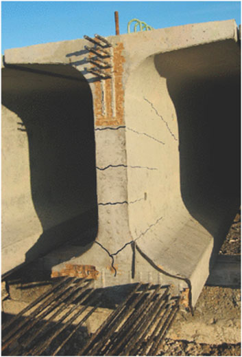
Figure 1. End zone cracks in a precast prestressed concrete beam (derived from Okumus and Oliva, 2013).
The prevalent approach to managing the end zone cracks involves ensuring adequate vertical reinforcement in the zone, as established by extensive research, including NCHRP Report 654 by Tadros et al. (2010) which explored the assessment and repair of end zone cracking in prestressed concrete girders. As per the AASHTO LRFD Bridge Design Specifications (AASHTO, 2020), vertical reinforcement is required to counteract four percent of the total prestressing force at the time of prestress release, positioned as close to the girder end as feasible. When girders incorporate a large number of prestressing strands, congested reinforcing configurations become essential to effectively control the cracking. More importantly, the end zone cracks cannot be eliminated, primarily because the girders are prestressed along their lengths only, i.e., there is no prestressing along their heights. As a result, the bursting force at prestress release causes the girder ends to crack. To resolve the problem of end zone cracking, this paper presents an innovative solution using Shape Memory Alloys (SMAs) to apply vertical prestressing at the girder ends.
SMAs are unique materials that undergo a reversible solid-solid phase transformation between two primary phases: martensite and austenite (Ozbulut and Hamilton, 2015). Their distinct property is the ability to endure large deformations and revert to their original shape either by stress removal (superelasticity) or heating (shape memory effect) (Alam et al., 2007). At lower temperatures, SMAs are predominantly in the martensite phase, transforming to austenite upon heating. This transformation is characterized by four distinct temperatures: martensite start (Ms), martensite finish (Mf), austenite start (As), and austenite finish (Af), where the SMA is fully martensitic below Mf and fully austenitic above Af (Figure 2).
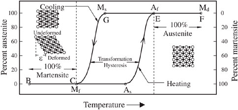
Figure 2. Phase transformation and change in SMAs’ crystalline structure (sourced from Alam et al., 2007).
SMAs, widely used in civil engineering, have mechanical properties that significantly vary based on their metal composition. Popular SMAs include NiTi, NiTiNb, and iron-based varieties. Pioneering work by Maji and Negret (1998) utilized NiTi SMAs’ shape memory effect for concrete beam prestressing. SMA strands, initially pretensioned, were embedded in mortar beams, and upon curing, activated by heat to induce prestressing. El-Tawil and Ortega-Rosales (2004) tested small mortar beams prestressed with SMA tendons. These prestrained tendons, when heated, generated significant prestressing force in the beams. Their studies comparing 2.5 mm NiTi and 6.3 mm NiTiNb wires found that while NiTi showed substantial recovery stress, NiTiNb was more suitable for permanent applications due to its sustained stress after heat removal. Sherif et al. (2014) explored self-post-tensioning of concrete beams using SMAs, leveraging the heat of hydration from grouts to activate NiTiNb alloys. This method achieved recovery stresses over 500 MPa post-cooling. Moser et al. (2005) investigated SMA short fibers for prestressing concrete beams. They shaped SMA wires by inelastic elongation into loops and stars, embedding them in mortar prisms. Upon heating the set mortar, the SMAs were activated, generating recovery stress that prestressed the specimens. This process effectively induced compressive stresses of up to 7 MPa, thus demonstrating the effectiveness of SMA fibers in prestressing concrete. These studies collectively illustrate the versatility and efficacy of SMAs in enhancing concrete structures, particularly in prestressing applications. The diverse methods of application and types of SMA used reflect the growing potential of these materials in modern structural engineering.
Soroushian et al. (2001) utilized iron-based SMAs for the repair and strengthening of concrete structures. They demonstrated that these alloys could create post-tensioning forces in structural systems. SMA rods were effectively used to convey corrective forces for the reinforcement and repair of concrete beams, specifically in bridge beams lacking adequate shear strength. Andrawes (2019) developed an innovative Adaptive Prestressing System (APS) for concrete crossties using SMAs. In his research, NiTiNb SMA wires were used to apply prestress at targeted areas of the crossties. Various configurations of SMA prestressing systems, including straight, L-shaped, and U-shaped wires, were tested, confirming the ability of SMA wires to induce prestressing forces precisely where needed. Sinha et al. (2020) proposed a novel post-tensioning method using unbonded near-surface mounted NiTiNb SMA wires. When these wires, prestrained by 2.5%, were Ohmic heated in a constrained environment, they generated a recovery stress of about 500 MPa. This technique was applied to pre-cracked concrete girders, where heating the SMA wires significantly reduced crack widths by up to 74%, showcasing the potential of SMAs in repair of concrete structures.
Numerous researchers have investigated the potential of using SMAs for introducing prestress in concrete beams, primarily focusing on new construction or the repair and strengthening of existing concrete structures. However, the application of SMAs, specifically at the end zones of precast prestressed concrete girders, has not yet been explored. This study marks the first endeavor to evaluate the feasibility of using SMAs to increase splitting resistance at end zones of prestressed concrete girders. By incorporating SMAs to introduce vertical prestressing at the girder ends, this innovative approach is expected to contribute to the development of more durable and reliable prestressed concrete structures. The study was approached in three steps. First, experiments were conducted to characterize the mechanical properties of various SMAs. Next, the effectiveness of SMA in prestressing in small beam specimens was investigated. Finally, a full-scale prestressed concrete girder with SMAs placed at the end zone was studied, incorporating insights from the previous steps. This paper presents the experimental studies, results, and discussions.
2 Experimental study
In this study, several suppliers were consulted to source NiTi and NiTiNb SMAs. However, the majority of these suppliers were only able to provide NiTi SMAs in small diameters, with no suitable NiTiNb SMAs available. Consequently, the research team utilized NiTi SMA wires, strands, and cables from a single supplier. Table 1 details these materials, including their descriptions, cross-sectional areas, and austenite finish (Af) temperatures.
The experimental study included tension tests on SMA wires, strands, and cables to determine their stress-strain relationships. It also featured small-scale beam tests to evaluate the potential of implementing prestressing in concrete beams with SMA components. In addition, a full-scale beam test was performed to explore the effectiveness of SMA cables in mitigating end zone cracking upon prestress release.
2.1 Tension tests of the SMA wires, strands, and cables
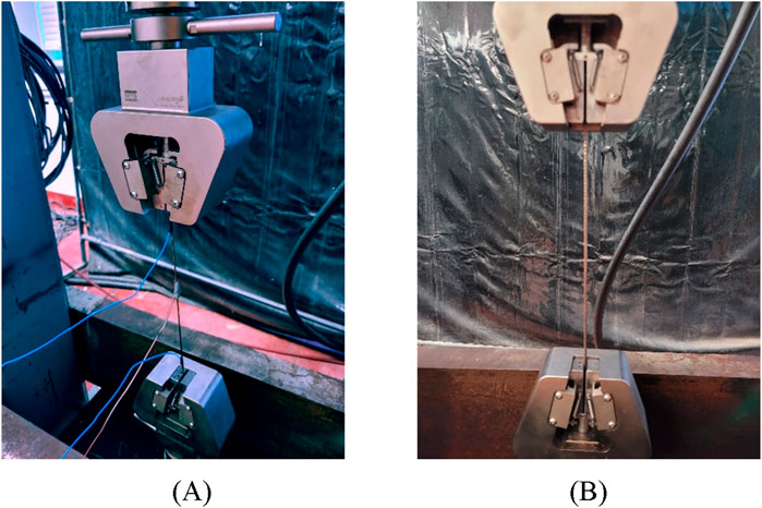
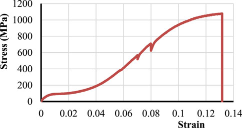
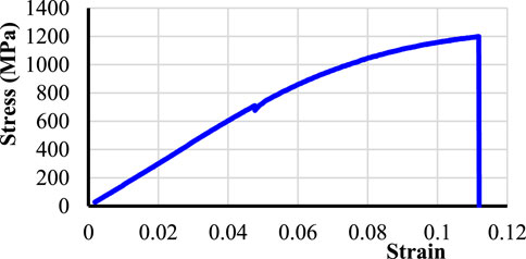
An MTS machine with MTS Advantage™ Wedge Grips was used to assess the stress-strain behavior of SMA wires and strands until failure. Each wire or strand was secured with a clear length of 254 mm in-between the grips (Figure 3). The SMA material was kept at ambient temperatures outside of the phase transition range and cut to the desired specimen length. The SMA cable consisted of seven strands, which were separated into individual strands after cutting for testing. During testing, a displacement-controlled approach was adopted, applying a loading rate of 5.1 mm per minute. An initial preload of 89 N was applied to rectify any sag and spiral pre-existing shape present in the wire and strand specimens. Test data was recorded after the load and displacement associated with this low preload were zeroed out. The resulting stress-strain diagrams for the wire and strand are depicted in Figures 4, 5, respectively. It was observed that the wires exhibited an ultimate tensile strength of roughly 1,069 MPa, accompanied by a strain of about 13%. In comparison, the strands demonstrated an ultimate strength of approximately 1,200 MPa with an ultimate strain near 11%.
Due to the limitations of the MTS machine’s grips for accommodating the SMA cable, its tensile properties were captured using a hydraulic mono-strand jack setup. This involved positioning ultra-high strength concrete (UHPC) blocks adjacently with the cable threaded through slots within these blocks. One end of the cable was anchored using a chuck, whereas the opposite end was tensioned using the jack, as illustrated in Figure 6. This setup facilitated the testing of two cables up to their failure point, which occurred at load levels around 38.3 kN.
2.2 Prestrained SMA wires, strands, and cables
SMA in the martensite phase subjected to inelastic deformation can recover its original shape with heat application to follow the phase transformation highlighted in Figure 2. Such inelastic deformation is introduced in the mechanical prestraining of SMA specimens. Prestrained SMA, prevented from freely recovering its original shape upon heat application, may be used to introduce counteracting stresses in the end zone of the prestressed girder. SMA specimen prestrained to known residual strain from a loading and unloading cycle will be anchored or bonded into concrete beams.
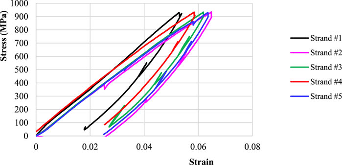
At ambient temperature, the MTS machine was employed to load and unload the SMA wires and strands, inducing residual strains. The maximum stress levels applied to both wires and strands were intentionally kept slightly below their ultimate tensile strengths to optimize the induction of residual strains. For the unloading phase, a force-control setting was utilized, operating at a rate of 22.2 N per second. This procedure led to the generation of residual strains of approximately 8% in the wires and 2% in the strands, respectively. The stress-strain behaviors of the wires and strands during these loading and unloading cycles are illustrated in Figures 7, 8. This experiment was repeated with five wires and five strands, yielding generally consistent results across samples of the same type. The SMA cables were tensioned using the mono-strand jack up to a force of 34.7 kN and then gradually released, resulting in residual strains. Consequently, the cables exhibited residual strains of about 1.7%.
2.3 Small-scale beam tests
To assess the feasibility of applying prestressing to concrete beams, prestrained NiTi wires, strands, and cables were embedded in small-scale beams made from either Type-M mortar or concrete. The SMA reinforcement was either bonded or unbonded with the mortar or concrete. Table 2 presents the beam details, including SMA reinforcement types, the material used (mortar or concrete), cross-sectional dimensions, beam lengths, and the bonding status of the SMA reinforcement. Mortar was used for Beam Nos. 1 and 2, while concrete was used for Beam Nos. 3 and 4. All beams included bonded SMA reinforcement, except for Beam No. 3, which had unbonded reinforcement. Subsequent sections will delve into the specifics of each specimen type and discuss their respective test outcomes.
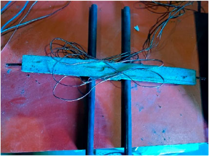
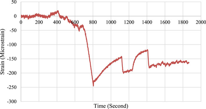
The setup for testing Beam No. 1, depicted in Figure 9, incorporated two bundled and mortar-bonded SMA wires. Strain gauges were placed on each side of the beam at midspan to measure axial strain. Figure 10 shows the gauges’ average readings over time, in which there was a notable decrease in strain readings around 800 s due to the wires’ recovery stress from electrical heating. Initially, the beam experienced a maximum compressive strain of about 250 microstrain. Subsequently, strain levels decreased as the concrete expanded from heating. As the temperature of the concrete gradually decreased, the beam’s compressive strain stabilized at approximately 160 microstrain towards the end of the observation period.
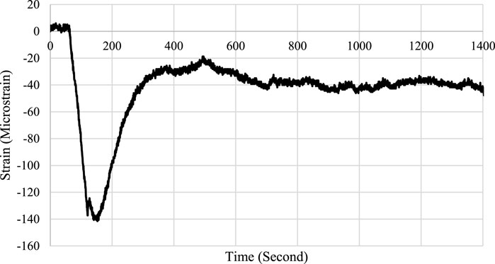
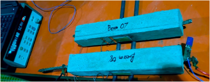
The experimental setup for Beam No. 2, illustrated in Figure 11, featured a single SMA strand bonded with mortar. A strain gauge was affixed to each side face of the beam at midspan to monitor axial strain. Figure 12 presents the average strain readings from both gauges over time, following the electrical activation of the strand. The activation resulted in a peak compressive strain in the beam of around 140 microstrain. As the concrete’s temperature normalized to ambient conditions, the compressive strain reduced to about 40 microstrain, indicating a considerable loss of the strand’s recovery stress.
Figure 13 illustrates the experimental setup for Beam No. 3, featuring an SMA cable within a PVC pipe, unbonded with the concrete. The cable’s ends were secured using chucks at both ends of the beam, with one anchor fully seated when the cable was prestrained. Subsequent re-tensioning of the cable to around 3.4 kN compensated for any anchor set loss. Strain gauges were affixed to each side of the beam at midspan to monitor axial strain. Figure 14 depicts the average strain readings over time from these gauges. Upon electrical heating of the cable, the beam experienced a peak compressive strain of 50 microstrain, corresponding to a compressive stress of approximately 1.2 MPa in the concrete beam. This indicated the induced recovery stress generated a compressive force near 3.1 kN. However, this recovery stress diminished once the heating ceased.
Figure 15 presents the setup for Beam No. 4, which incorporates an SMA cable directly bonded to the concrete. Strain gauges were affixed to both sides of the beam at midspan to measure axial strain. The average strain measurements from these gauges over time are depicted in Figure 16. Activation of the SMA cable induced a peak compressive strain of 10 microstrain in the beam, corresponding to a compressive stress of approximately 0.24 MPa in the concrete. This indicated the recovery stress from the SMA cable generated a compressive force of about 0.6 kN. The minimal recovery stress observed is attributed to the beam’s short length, which was insufficient to develop the cable. Similarly to Figure 14, the recovery stress gradually diminished after the cessation of heating.
2.4 Full-scale beam test
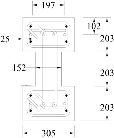
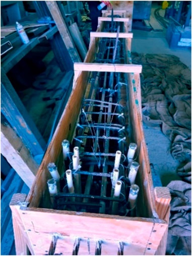
A concrete beam was constructed in the laboratory to evaluate the effectiveness of SMAs in mitigating end zone cracking at prestress release. Illustrated in Figure 17, the beam section is comparable to an AASHTO Type I beam with simplified flanges to facilitate its fabrication. The beam measures 610 mm in height with a 152 mm wide web. Flanges are 305 mm in width and are 203 mm thick. Provided reinforcement included #13 stirrups in both flanges, pairs of #13 C-bars along the web, and #13 longitudinal bars. The C-bars were spaced at approximately 610 mm along the beam length except at the ends, in which two pairs were placed at 254 mm and 406 mm from each beam end, respectively. The shear reinforcement was intentionally provided far from the beam end to eliminate its contribution to the splitting resistance. The stirrups in the flanges were spaced at 102 mm for a distance of 610 mm from each beam end to provide sufficient confinement for the prestressing strands. Four 15.2 mm-diameter, Grade 1862 strands were placed in flexible polymer plastic tubing in each flange. Figure 18 shows the layout of the prestressing strands and reinforcing bars. One of the beam’s ends included three pairs of 13 mm-diameter PVC pipes installed vertically to house the SMA cables.
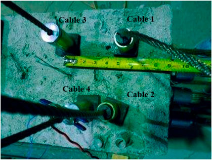
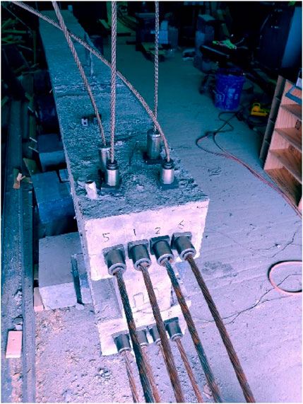
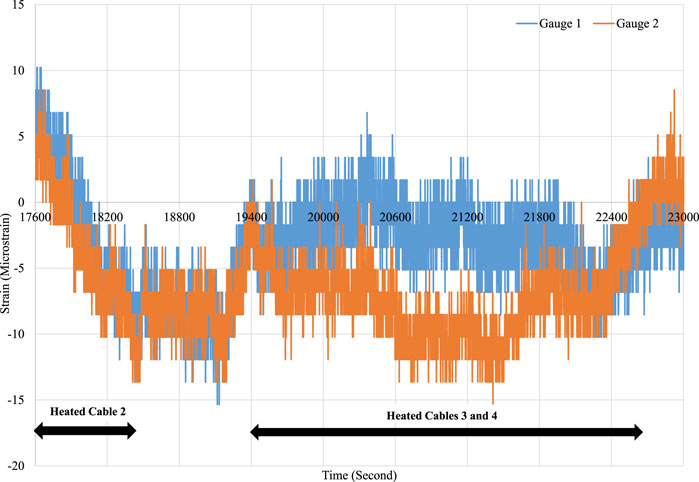
The beam formwork was removed 3 days after the concrete pour when the concrete strength reached about 23 MPa based on cylinder tests. Four SMA cables were eventually installed at one beam end and the cable ends were anchored by chucks. The first cable was electrically heated prior to installation of the other three cables. The heating was stopped after the cable’s temperature reached approximately 100 C and the current was about 39 amps. Afterward, the remaining three cables were placed. Their distances measured to the beam end varied from 89 to 229 mm to allow for evaluation of their effects on the splitting resistance (Figure 19).
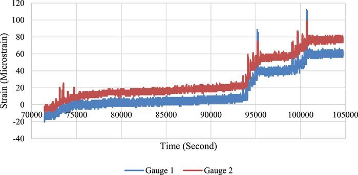
The longitudinal steel strands were post-tensioned 4 days after the concrete pour. They were numbered and tensioned in a sequence that ensured symmetry (see Figure 20). The strands were jacked using a hydraulically operated monostrand jack and anchored with strand chucks. Two strain gauges were installed at the end face of the beam web. The strands were tensioned sequentially at one end of the beam, from strand No. 1 to 8 as shown in Figure 20. On average, each strand was tensioned to approximately 60.7 kN. The strands were not fully tensioned to the maximum allowable force due to the relatively low concrete strength at the time of testing.
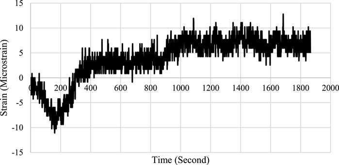
The readings of the two strain gauges at the beam end were collected and plotted in Figures 21–23. Figure 21 shows the gauge readings when Cable 1 was electrically heated. The recovery stress of the SMA cable resulted in strain changes of approximately 15 microstrain at one gauge and 10 microstrain at the other gauge. As an average, these strains corresponded to approximately 0.3 MPa compressive stress in the beam web concrete. Similarly, Figure 22 illustrates the gauge readings when Cables 2 to 4 were electrically heated. Activating Cable 2 resulted in approximately 15 microstrain at both gauges. Given their further distance from the beam end, Cables 3 and 4 exerted a less pronounced effect, contributing to around 10 microstrain each. Collectively, the four cables exerted roughly 40 microstrain or 1.0 MPa of compressive stress at the beam’s end mid-height. Following the tensioning of all steel strands, an average strain change of 80 microstrain was observed (Figure 23), equating to 1.9 MPa of tensile stress at the instrumented locations. Given that the concrete’s modulus of rupture is about 3.0 MPa, the tensile stress generated was insufficient to cause cracking in the web concrete.
3 Discussions
Initially, attempts to heat the SMAs used a heat gun in conjunction with a direct power supply. However, it soon became evident that the heat gun’s inability to uniformly distribute heat made it less effective compared to direct electrical heating. Direct electrical heating required a relatively high current, up to 40 amps, to heat the SMAs efficiently and achieve the desired temperature uniformly.
The effectiveness of bonded SMAs in generating prestress in a concrete beam is significantly influenced by the surface conditions of the SMAs. Bending or anchoring the ends of the SMAs can enhance the development of the reinforcement. These modifications improve the interaction between the SMAs and the surrounding concrete matrix, optimizing the engagement and leveraging the recovery stress to maximize the prestressing effect. For unbonded SMAs, the effectiveness of the anchors used should be carefully chosen to achieve the desired prestress. It is important to minimize anchor set losses when implementing an unbonded system to ensure that the intended prestressing force is effectively transferred to the concrete beam. For shorter concrete members, it may be practical to use unbonded SMAs to engage the prestressing force more efficiently.
In the full-scale beam test, the application of SMA cables resulted in approximately 1.0 MPa of compressive stress in the beam web. This demonstrates that, with a sufficient amount of SMA cables, the induced prestressing force can be substantial and effective in preventing concrete cracking associated with bursting forces at prestress release. Laboratory tests revealed that NiTi SMAs lost a significant portion of their recovery stresses once the applied heat was removed. This finding highlights the potential advantage of using alternative SMAs, such as NiTiNb, which exhibit a wider thermal hysteresis. As recommended by the research of El-Tawil and Ortega-Rosales (2004), NiTiNb SMAs may be more suitable for real-world applications due to their improved performance characteristics in maintaining recovery stresses.
4 Conclusion
This paper investigated the feasibility of using SMAs to introduce vertical prestress at the ends of pretensioned concrete beam girders. The study involved testing small-scale mortar and concrete beams incorporating SMA wires, strands, and cables to assess their shape memory effects and the impact of induced prestressing. Both unbonded and bonded SMAs were evaluated for their effects on resulting compressive strains in the specimens. In addition, a full-scale concrete beam was produced to further assess the effectiveness of SMAs in mitigating end zone cracking caused by the release of prestressing forces. The end zone of the post-tensioned concrete beam was instrumented to measure vertical strains resulting from the SMA’s shape memory effects. Based on the laboratory testing results, the following conclusions are drawn:
1. Throughout the small- and full-scale beam tests, it was consistently observed that prestressing forces could be successfully introduced upon the activation of the SMAs. This underscores the potential of SMAs in structural engineering applications, specifically in introducing vertical prestress at the ends of precast prestressed concrete beams. The ability of SMAs to generate prestressing forces upon activation demonstrates their effectiveness and versatility in enhancing the performance and durability of concrete structures.
2. In the full-scale beam test, the SMA cables provided resulted in substantial vertical compressive stress along the beam web. This induced vertical prestress can effectively increase the beam’s splitting resistance, thereby reducing the concrete cracking during the release of prestressing forces. The successful application of this prestressing technique underscores its potential to improve the overall structural performance of precast prestressed concrete beams by mitigating issues commonly associated with prestress release.
3. The laboratory tests revealed that the recovery stresses of the NiTi wires, strands, and cables were largely lost once the electrical heating was removed. Despite this limitation, the tests validated the proposed concept of using SMAs to introduce vertical prestress at the ends of precast prestressed concrete beams. However, other types of SMAs that exhibit a wider thermal hysteresis may be more effective in providing a permanent prestressing force.
Data availability statement
The original contributions presented in the study are included in the article/supplementary material, further inquiries can be directed to the corresponding author.
Author contributions
CS: Conceptualization, Funding acquisition, Methodology, Supervision, Writing–original draft, Writing–review and editing. OB: Data curation, Formal Analysis, Writing–review and editing. DK: Data curation, Writing–review and editing. NF: Data curation, Writing–review and editing.
Funding
The author(s) declare that financial support was received for the research, authorship, and/or publication of this article. This work was supported by the Louisiana Transportation Research Center SIO number DOTLT1000301.
Acknowledgments
The authors would like to thank Louisiana Transportation Research Center for funding this project.
Conflict of interest
Author OB was employed by Simpson Gumpertz & Heger Inc. Author DK was employed by Crosby Group.
The remaining authors declare that the research was conducted in the absence of any commercial or financial relationships that could be construed as a potential conflict of interest.
Publisher’s note
All claims expressed in this article are solely those of the authors and do not necessarily represent those of their affiliated organizations, or those of the publisher, the editors and the reviewers. Any product that may be evaluated in this article, or claim that may be made by its manufacturer, is not guaranteed or endorsed by the publisher.
References
Alam, M. S., Youssef, M. A., and Nehdi, M. (2007). Utilizing shape memory alloys to enhance the performance and safety of civil infrastructure: a review. Can. J. Civ. Eng. 34 (9), 1075–1086. doi:10.1139/l07-038
Andrawes, B. (2019). Adaptive prestressing System for concrete crossties (No. Rail safety IDEA project 33).
El-Tawil, S., and Ortega-Rosales, J. (2004). Prestressing concrete using shape memory alloy tendons. Struct. J. 101 (6), 846–851. doi:10.14359/13460
Maji, A. K., and Negret, I. (1998). Smart prestressing with shape-memory alloy. J. Eng. Mech. 124 (10), 1121–1128. doi:10.1061/(asce)0733-9399(1998)124:10(1121)
Moser, K., Bergamini, A., Christen, R., and Czaderski, C. (2005). Feasibility of concrete prestressed by shape memory alloy short fibers. Mater. Struct. 38, 593–600. doi:10.1617/14327
Okumus, P., and Oliva, M. G. (2013). Evaluation of crack control methods for end zone cracking in prestressed concrete bridge girders. PCI J. 58 (2), 91–105. doi:10.15554/pcij.03012013.91.105
Ozbulut, O., and Hamilton, R. (2015). Smart concrete bridge girders using shape memory alloys. Mid-Atlantic Univ. Transp. Cent.
Russell, H. G. (2017). Control of concrete cracking in bridges (No. Project 20-05, Topic 47-01). Washington, DC: The National Academies Press.
Sherif, M., Ozbulut, O., Landa, A., and Hamilton, R. F. (2014). “Self-post-tensioning for concrete beams using shape memory alloys,” in Smart materials, adaptive structures and intelligent systems, 46155. American Society of Mechanical Engineers, V002T04A014. doi:10.1115/smasis2014-7564
Sinha, A., Tatar, N., and Tatar, J. (2020). Rapid heat-activated post-tensioning of damaged reinforced concrete girders with unbonded near-surface mounted (NSM) NiTiNb shape-memory alloy wires. Mater. Struct. 53, 88–15. doi:10.1617/s11527-020-01522-8
Sirca, G. F., and Adeli, H. (2005). Cost optimization of prestressed concrete bridges. J. Struct. Eng. 131 (3), 380–388. doi:10.1061/(asce)0733-9445(2005)131:3(380)
Soroushian, P., Ostowari, K., Nossoni, A., and Chowdhury, H. (2001). Repair and strengthening of concrete structures through application of corrective posttensioning forces with shape memory alloys. Transp. Res. Rec. 1770 (1), 20–26. doi:10.3141/1770-03
Keywords: shape memory alloys, vertical prestress, end zone cracking, bursting force, splitting resistance, precast prestressed concrete girder, recovery stress
Citation: Sun CS, Babarinde O, Kuruppuarachchi D and Farzana N (2024) Mitigation of end zone cracks in precast prestressed concrete girders using shape memory alloys. Front. Mater. 11:1389840. doi: 10.3389/fmats.2024.1389840
Received: 22 February 2024; Accepted: 01 October 2024;
Published: 17 October 2024.
Edited by:
Yao Ding, Chongqing University, ChinaReviewed by:
Xiaohua Li, Chongqing University, ChinaRoberto Nascimbene, IUSS - Scuola Universitaria Superiore Pavia, Italy
Copyright © 2024 Sun, Babarinde, Kuruppuarachchi and Farzana. This is an open-access article distributed under the terms of the Creative Commons Attribution License (CC BY). The use, distribution or reproduction in other forums is permitted, provided the original author(s) and the copyright owner(s) are credited and that the original publication in this journal is cited, in accordance with accepted academic practice. No use, distribution or reproduction is permitted which does not comply with these terms.
*Correspondence: C. Shawn Sun, c2hhd24uc3VuQGNzdW4uZWR1
 C. Shawn Sun
 Oluwatobi Babarinde
 Dinesha Kuruppuarachchi3
