 Linlin Shen1
 Tingyu Wang
- 1Rioh Traffic Safety Co. Ltd, Beijing, China
- 2Transport Development Group Co. Ltd. of Henan Province, Zhengzhou, China
- 3Expressway Group Co. Ltd. of Hunan Province, Changsha, China
Considering the difficulty and high cost of guardrail installation in the transition between the highway subgrade and the bridge, this paper proposes a wing-wall-free guardrail based on comprehensive research. It has carried out a performance analysis of material Q690 before proposing the scheme. It is found that this type of material has high yield strength and tensile strength as well as high plasticity. Accordingly, the guardrail structure of the transition section of the wing-wall-free guardrail is designed, and the DYNA numerical simulation is carried out to optimize the structure. Moreover, vehicle crash tests are used to verify the performance of the newly designed guardrail. The results of the above-mentioned research methods are as follows: the vehicle crash tests show that the wing-wall-free guardrail can reach a protection level of Grade SB, with a collision energy of 280 KJ. All performance indicators meet the industry standards. The guardrail can be used in the transition between W-beam subgrade guardrails and concrete or combined bridge barriers. This proposed guardrail is beautifully designed with low cost and great conveniency for installation and maintenance.
Introduction
The highway guardrail system is mainly composed of roadside guardrails, median barriers, bridge barriers, and the transition between the guardrails. Any component failing to meet the protection requirements may become hidden hazards. Guardrail transition is a critical part of road safety facilities. According to statistics of highway traffic accident in the United States, 50% of roadside guardrail crash occurred at the road-bridge transition, and 50% of bridge barrier crash occurred at the terminal of the barrier, with a high death rate and injury rate. The design of the bridge barrier terminal faces many problems. Roadside guardrails and bridge barriers have different stiffnesses and strengths. According to studies of many accidents, when a car impacts into the transition of the roadside guardrail and the bridge barrier, it may be snagged or rolled over, resulting in serious injury.
The traditional W-beam steel guardrail is a semi-rigid continuous structure with beams and posts. With a certain stiffness and flexibility, this type of guardrail can absorb the collision energy and redirect the vehicle through structural deformation. In comparison, the concrete barrier is a rigid guardrail with almost no deformation. It reduces the momentum mainly through its cross-section, the shape of which allows the vehicle to climb up, and the collision energy is thus absorbed. In this way, the vehicle will be guided out of the guardrail. Transition refers to the highway guardrail between two types of guardrails with different protection levels. It serves as a smooth connection that changes from one degree of stiffness to another. Most transitions are located between the W-beam steel guardrail of the subgrade and the concrete bridge barrier. Scholars around the world have intensively studied the safety performance of guardrails. However, they have focused more on bridge barriers and fixed or removable guardrails for subgrades but less on the transition between the bridge and the subgrade.
The design of transition guardrails is mainly based on the recommendations from Design Guidelines for Highway Safety Facilities (Old Design Guidelines) (JTG/T D81-2006, 2006), in which the transition is made by adding a beam to the lower part of the subgrade W-beam guardrail and anchoring it to the concrete barrier. According to the study of Zhou et al. (2016), the same type of structure was insufficient to protect drivers and left great safety hazards. To solve this problem, Chinese scholars have carried out relevant research. Song and Deng (2012) designed a Grade A transition structure that changed from a W-beam to a four-wave beam, but the collision point was not at the transition part and had weak protection. According to the Old Design Guidelines, road-bridge transitions should have “upper beam anchored, and lower beam terminal treated.” Zhou et al. (2016) applied finite element simulation to verify this method. The results showed that such a method failed to meet the standards. After adding posts to the original structure and improving the lower beam design, its protection degree could reach Grade A. However, it was only suitable for specific structures. This method, which had not completed the truck crash test, did not meet current Standard for Safety Performance Evaluation of Highway Barriers” (JTG B05-01-2013, 2013).
Current Design Guidelines for Highway Safety Facilities (JTG/T D81-2017, 2017) stipulates that the transition between the subgrade guardrail and the bridge barrier should be designed as follows: setting up a wing wall at the end of the rail or connecting a semi-rigid guardrail to the rigid guardrail. The wing wall can be set at the end of the bridge, modified from the bridge barrier, or independently established at the subgrade section. Another method is to extend the subgrade W-beam guardrail and anchor it to the concrete bridge barrier. Moreover, more posts should be added to the terminal components of the W-beam guardrail. This method provides a continuous change in guardrail stiffness. However, the transition between the Grade A subgrade W-beam guardrail and Grade SB concrete bridge barrier cannot meet current safety standards. To solve this problem, An et al. (2021) of CCCC First Highway Consultants Company Limited modified the original transition and developed a Grade SB protective structure based on finite element simulation. This structure was made of aluminum foam, with a two-wave section. However, it did not participate in any vehicle crash test, thus not satisfying the Standard for Safety Performance Evaluation of Highway Barriers (JTG B05-01-2013).
With the development of the automobile industry, the speed of automobiles continues to increase, so does the number and severity of automobile accidents. Studying the crash safety performance of automobiles has become an indispensable and important part of vehicle development. Traditional vehicle development uses tests to obtain the crash performance of the whole vehicle, but it requires many time-consuming and expensive test cycles. In recent years, computer-aided engineering (CAE) technology becomes available and has been applied in many fields of vehicle development. This technology has the advantage of a very short cycle of vehicle development (Kolb, 1984; Harb et al., 1993; Nicoll-Senft and Seider, 2009; Li et al., 2021; Liu et al., 2021; Zhang et al., 2021; Zhao et al., 2021). In the simulation of car collisions, foreign research institutions and universities have launched many kinds of finite element simulation calculation software, among which LS-DYNA, PAM-CRASH, and MSC.DYTRAN are the most popular commercial ones in practice. The core of these kinds of finite element software is the theory of DYNA developed by Lawrence Livermore National Laboratory in the United States in the 1970s. LS-DYNA is large dynamic nonlinear finite element analysis software with a wide range of applications. It is able to solve geometry, material and contact nonlinearity, explosion, dynamics, impact, heat transfer, and fluid and fluid–structure interaction problems. LS-DYNA has multiple algorithms such as Lagrange, ALE, and Euler. With explicit and implicit solution functions and interchangeable quality, this software can analyze fluid–structure interaction problems, thermal problems, and structural problems and carry out static and nonlinear dynamic analysis. Moreover, LS-DYNA has a variety of materials in its material library, which helps simulate composite materials and meet the needs of the users with its customization feature. LS-DYNA’s cell bank is a complete family of cell banks with various units, each with many different algorithms. Multiple contact methods can simulate a variety of contact problems such as connection failures, static friction, dynamic friction, and the interaction between fluids and solids on contact surfaces. ALE and Euler algorithms help avoid cell aberrations and can provide high-quality fluid–structure interaction analysis (Gilbert and Kenneth, 1985). The boundary element method (Hallquist, 1998; LS-DYNA, 2006) solves the problem of steady-state and transient flows of incompressible viscous fluids. The SPH algorithm, also known as the smooth particle hydrodynamics algorithm, which belongs to the meshless Lagrange algorithm, is suitable for solving a variety of complex problems.
The Design Guidelines for Highway Safety Facilities (JTG/T D81-2017) stipulates that a wing wall should be set up at the end of the guardrail as transition or connecting the semi-rigid guardrail to a rigid guardrail as transition. However, wing wall installation is both difficult and expensive in practice. Therefore, only simple processing is adopted. If the semi-rigid guardrail is required to be connected to a rigid guardrail, even the processing step is neglected. To improve road safety and increase the protective capacity of traffic facilities in China, original transitions should be upgraded. Traditional renovation measures include component replacement and establishment of wing walls. These measures are expensive and time-consuming and not suitable for large-scale renovation of transitions. Therefore, an inexpensive and time-saving renovation scheme that meets safety requirements is urgently needed. To conclude, this paper has developed a wing-wall-free transition through the material mechanical analysis, numerical simulation analysis, and real vehicle test. This kind of low-cost guardrail can be widely applied and is convenient for maintenance.
Test
The electronic universal test machine is used to conduct quasi-static compression test on specimens of the guardrail material. This tensile testing adopts a loading strain rate of 1 × 10⁻³ S−1 at room temperature. The standard mechanical testing of materials is carried out with a dog-bone-shaped specimen (Figure 1), of which the holding parts at both ends have a relatively large diameter and the test part in the middle is both even and thin. The arc that connects the test part with the holding part has a radius of R. The length and width of the test part and the holding parts are set to be L0, L1, b0, and b1. The specimen’s thickness is set to be a0. Generally, the guardrail is made of a thin-walled sheet material, so the specimen is a thin-walled sheet. Based on the requirements of the Metal Material-Tensile Test-Part 1: Room Temperature Test Method (GB/T 228.1-2010), the tensile specimen is cut from a plate and processed into the desired shape.
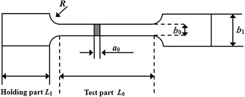
FIGURE 1. Schematic diagram of the tensile specimen.
Table 1 shows the loading speed on various specimens, and the strain rate for every specimen is consistent. It is assumed that the strength limit of the material is 900 MPa, and Table 1 reveals the maximum tensile load of the specimen. Based on preliminary planning and calculations, a 100 kN machine is used for testing. The specimen is designed based on the requirements of Table 1 and Metal Material-Tensile Test-Part 1: Room Temperature Test Method (GB/T 228.1-2010). Each type of material is processed into six specimens, and each group performs at least three tests.

TABLE 1. Preliminary design parameters of quasi-static tensile specimens at normal temperature.
The stress–strain relationship of low-silver lead-free solder Sn0. 3Ag0. 7Cu is calculated as follows:
where
3 Test Results and Analysis
This paper adopts Q355 and Q690, two types of high-strength steel, to make the wing-wall-free guardrails for the subgrade–bridge transition. As the mechanical properties of Q355 have been thoroughly studied (Zhu et al., 2020), this paper has focused on the mechanical properties of Q690 high-strength steel at the strain rate of 1 × 10⁻³ S−1. Figure 2 shows the true stress–strain curve, which has an obvious yield platform. When this platform is surpassed, the flow stress will increase with strain until the necking fracture occurs. High-strength steel has a high yield strength of 745 MPa, great tensile strength, and a good plasticity, with an elongation rate of 17.1%.
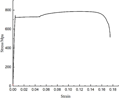
FIGURE 2. Curve of the static mechanical properties of Q690 high-strength steel.
Wang et al. (2021) obtained the in-field behavior of the CFRP composite pipes. In their study, quasi-distributed optical fiber sensing techniques were developed based on multiple configurations of fiber Bragg grating (FBG) sensing elements. They performed theoretical investigation on the dynamic response of the pipes and conducted experiments on cantilever CFRP pipes with surface attached FBGs in series and packaged FBG sensors. This was to check the feasibility and effectiveness of the proposed sensing technique. The results validated the good performance of the proposed sensors and the accuracy of the vibration analysis. Under extreme loading and environmental conditions, railway structures were vulnerable to deterioration and failure, leading to the interruption of the whole transportation system. Chan et al. (Sasy Chan et al., 2021) provided a state of the art of optical fiber sensing technologies and their practical application in railway infrastructures.
Since new materials are used in the research and development and the design of the transition section of the subgrade guardrail of the wing-free wall bridge, this study has analyzed mechanical properties of the material to better understand the material. For a more conservative simulation of the real vehicle test, this study has neither considered the strain hardening effect of the steel nor analyzed the mechanical properties of the steel under high strain rates.
Design of the Wing-wall-free Transition Guardrail and Numerical Analysis
Considering that the protection levels of most highway W-beam barriers of subgrades are Grade A and Grade SB and the wing-wall-free guardrails of subgrades and bridges should be easily applied, this paper adopts Grade SB as the protection degree of the transition. To make a smooth transition, the combined barrier of Grade SS (520 kJ) is selected for the bridge section and the W-beam guardrail of Grade A is selected for the subgrade section of the wing-wall-free transition.
Ding et al. (2021) optimized the basic assumptions of the damage specific strength theory. Existing test data were then analyzed based on the general form of the damage specific strength theory of multiaxial concrete and the characteristics of the failure envelope of ordinary concrete, recycled aggregate concrete, lightweight aggregate concrete, and isotropic rock. The result showed that monotonic, repeated, or reciprocating loading had little effect on the strength criterion of brittle materials. The Federal Highway Administration (FHWA) developed the CSCM concrete model during the simulation for highway safety protection analysis. Therefore, M159 material is selected as the concrete in the DYNA simulation process. The initial damage surface coincides with the yield surface, and the rate effects are modeled with viscoplasticity.
During the FEM barrier modeling, the material of the concrete barrier is simulated with the MAT159 material card in the LS-DYNA finite element software. The main input parameters are compressive strength and aggregate diameter. Concrete is coupled with steel bar that is made of Q235 low-carbon steel, with beam as the element property (Chen et al., 2021; Lin et al., 2021; Lu et al., 2021; Luo et al., 2021). The quadrilateral shell unit is adopted for the components of the W-beam guardrail. Considering the strain effect of the material, bolts that connect the resistance blocks, beams, and posts are of the same property of the beam unit. MAT24 and the shell are selected as the material model and element attribute, respectively.
Based on standard requirements, a small car, a medium-size bus, and a tractor trailer are used for numerical simulation and analysis, respectively. Table 2 shows the weight, collision speed, and collision angle of the vehicles.
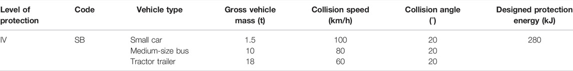
TABLE 2. Test collision conditions for the standard section, transition, and open guardrail of the median strip.
Preliminary Scheme
For the convenience of transport and installation, the transition adopts three beams to connect the W-beam guardrail with the combined barrier. Bracket frames are installed on the concrete base of the combined barrier to connect the beams. All components are made of Q355 steel, and the numerical model of the preliminary scheme is shown in Figure 3.
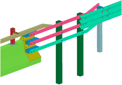
FIGURE 3. Structure diagram of the preliminary scheme.
Figure 4 shows a medium-size bus crashing into the guardrails. The vehicle does not penetrate through the guardrail, lean over, or override it. Instead, the guardrail provides a smooth redirection that allows the vehicle to move on as normal and stable, without a rollover. During vehicle collision, the guardrail remains intact, with no components piercing into the passenger compartment. Therefore, the preliminary scheme shows good averting and blocking effects for the Grade SB medium-size bus.
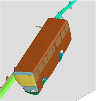
FIGURE 4. Preliminary scheme simulation for the medium-size bus crash.
Intermediate Scheme
The analysis of the preliminary scheme shows that the connection between the beam and the W-beam plate has a safety hazard, and the beam needs to be extended, which will increase the difficulty of material processing. Therefore, based on the preliminary scheme, the three beams are replaced with a W-beam plate and directly connected to the concrete barrier. In addition, a beam is added at the back of the W-beam guardrail to ensure the stiffness of the transition. To prevent the vehicle from crashing into the terminal of the bridge barrier, a friction beam is also added to the lower part of transition. The W-beam and friction beam are installed to the bracket frame of the bridge barrier. The W-beam plate is made of high-strength steel, and the rest of the structure is made of Q355 steel. Figure 5 shows the numerical model of the intermediate scheme.
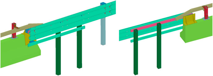
FIGURE 5. Structure diagram of the intermediate scheme.
Figure 6 shows the medium-sized bus crash. The vehicle does not penetrate through the guardrail, lean over, or override it. Instead, the guardrail provides a smooth redirection that allows the vehicle to remain stable without any significant snagging, pocketing, or rollover. During vehicle collision, the guardrail is not damaged, with no components piercing into the passenger compartment. Therefore, the intermediate scheme shows good averting and blocking effects for the Grade SB medium-size bus.
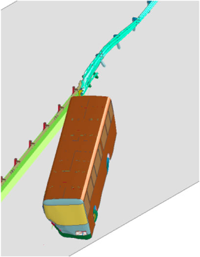
FIGURE 6. Simulation of the intermediate scheme of the medium-size bus crash.
Scheme Optimization
The crash simulation proves that the intermediate scheme meets the requirements of the Grade SB medium-size bus. Therefore, a friction beam is added to the lower part of the guardrail in the transition. It serves as a buffer to prevent the vehicle from colliding to the terminal of the bridge barrier. To improve the practicality of the transition, this paper installs a frame support on the concrete base of the bridge barrier. In this way, the W-beam guardrail of the subgrade can be successfully connected with the concrete or combined bridge barrier. From the subgrade part to the concrete barrier part, the spacing of posts is gradually reduced to ensure a smooth transition of the stiffness. The W-beam plate of the transition is made of high-strength steel, and all the components are made of Q355 steel. Figure 7 shows the specific structure.
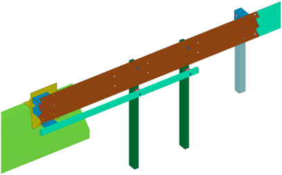
FIGURE 7. Structure diagram of the optimized scheme trailer.
Post-collision stress cloud diagrams and the optimized schemes show the stress distribution of the guardrail during the collision from the small car, the medium-size bus, and the tractor trailer (Figure 8). When the three models collide with the guardrail, the corrugated plate of the guardrail bears the maximum stress and suffers a greater impact. The maximum stress value is at the connection between the column and the corrugated plate and at the end of the bridge. This proves that the end of the bridge is the most dangerous place when the vehicle impacts the bridge head. Moreover, the guardrail can prevent the vehicle from colliding with the end of the bridge and eliminate the risk of accidents.
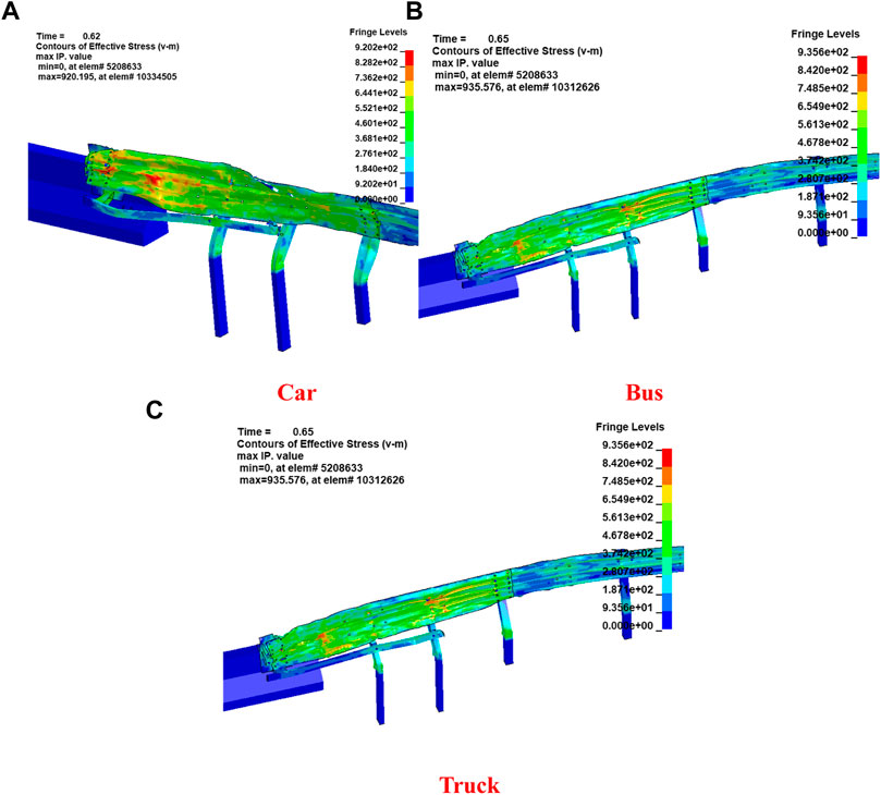
FIGURE 8. Post-collision stress cloud diagram of the small car, medium-size bus, and tractor-trailer crash optimization scheme. (A) Car, (B) Bus, and (C) Truck.
Figure 9 shows the small car, the medium-size bus, and the tractor trailer crashing with guardrails. These three types of vehicles do not penetrate through the guardrail, lean over, or override it. Instead, the guardrail provides a smooth redirection that allows the vehicle to remain stable without any significant snagging, pocketing, or rollover. During the crash, the guardrail is not damaged, and no components pierce into the passenger compartment. Therefore, the optimized scheme shows good averting and blocking effects for the Grade SB small car, medium-size bus, and tractor trailer.
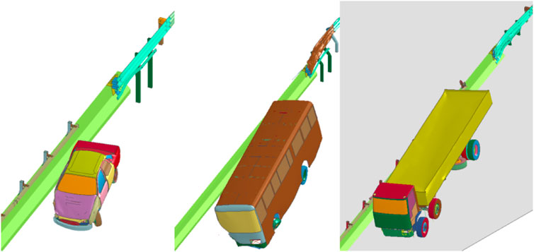
FIGURE 9. Crash simulation of the optimized scheme for the small car, medium-size bus, and tractor.
Test Scheme Design
Based on the optimized scheme, the terminals of the friction beam and the W-beam of the wing-wall-free guardrail in the transition are treated with an extended extruder head and an extruder head, respectively. The extended extruder head is installed for the friction beam’s terminal in the traffic direction. The guardrails in the subgrade section adopt either the W-beam or Thrie beam in practice. To ensure a smooth transition, a W to Thrie transition that connects the two kinds of beams can be adopted for testing. Figure 10 shows the details of the recommended transition design.
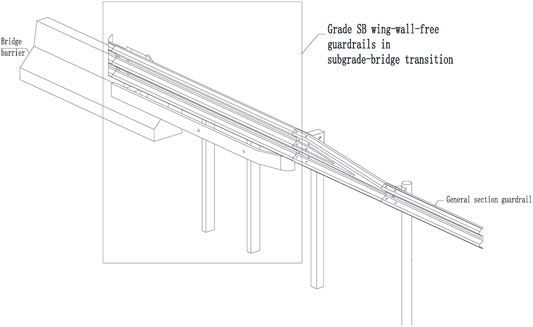
FIGURE 10. Structure of wing-wall-free guardrails in subgrade–bridge transition.
Crash Testing
To verify the safety performance of the wing-wall-free guardrail in subgrade–bridge transition, full-scale vehicle crash tests were conducted in the small car, the medium-size bus, and the tractor trailer. The tests are based on current crash testing requirements (Table 3) stipulated in the Standard for Safety Performance Evaluation of Highway Barriers (JTG B05-01-2013) Grade IV (SB). Table 3 shows the details:
(1) Test of the small car
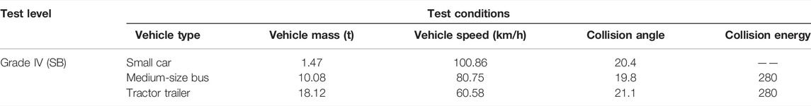
TABLE 3. Test conditions of the wing-wall-free guardrail in subgrade–bridge transition.
Figures 11, 12 are the photos of the guardrail before and after the crash test of the small car.
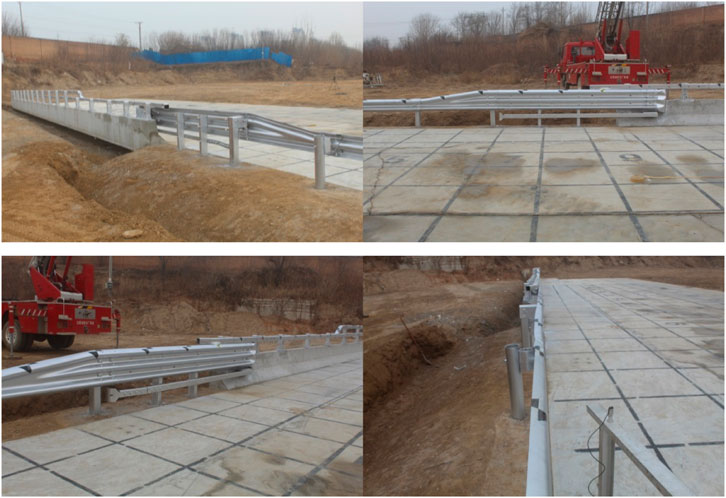
FIGURE 11. Guardrail before the crash test.
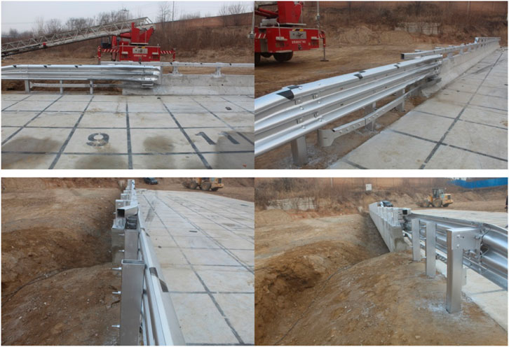
FIGURE 12. Guardrail after the crash test.
Figure 13 is the schematic diagram of the moving trajectory of the small car (right to left).
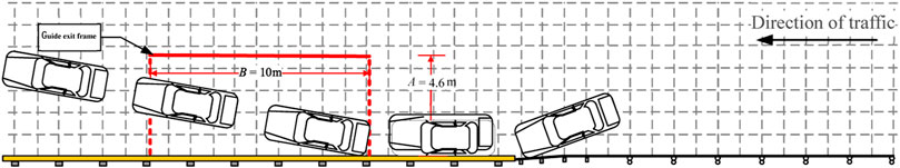
FIGURE 13. Schematic diagram of the moving trajectory of the small car (right to left).
After the small car collided with the guardrail, the vehicle did not cross, climb over, ride over, or go under the guardrail. Figure 11 shows photos of various angles of the guardrail before the passenger car’s collision. Figure 12 shows the state of each angle of the guardrail after the passenger car crash. After the vehicle collided with the guardrail, the vehicle was successfully redirected without causing serious damage to the guardrail, which basically retained the integrity. This study compared the photos before and after the collision test of the small car and the driving trajectory of the vehicle. During the collision of the small car, the guardrail was almost not deformed, and the components did not fall off. The bending was small, and the collision surface of the guardrail was almost not deformed. This indicates that the transition of the guardrail of the subgrade bridge without the wing wall has the guiding and blocking functions for the small car.
(2) Test of the medium-size bus
Figures 14, 15 are the photos of the guardrail before and after the crash test of the medium-size bus.
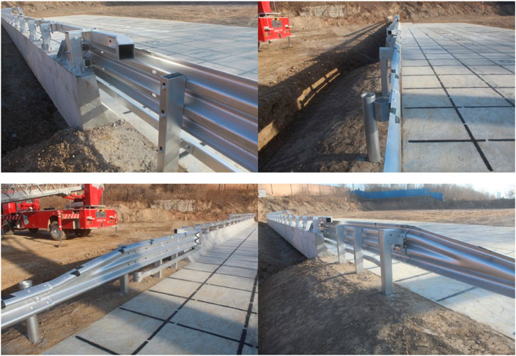
FIGURE 14. Guardrail before the crash test.
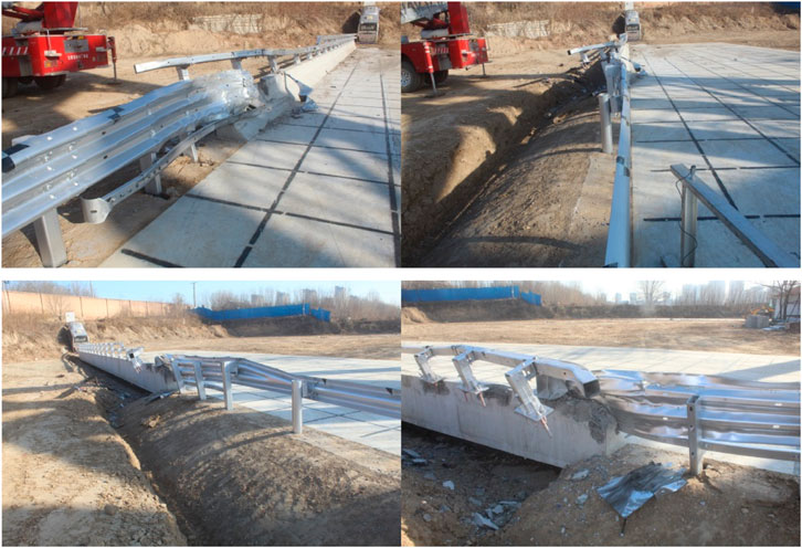
FIGURE 15. Guardrail after the crash test.
Figure 16 is the schematic diagram of the moving trajectory of the medium-size bus (right to left).
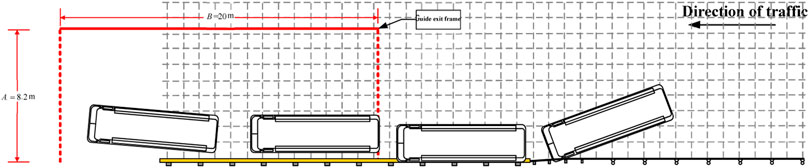
FIGURE 16. Schematic diagram of the moving trajectory of the medium-size bus (right to left).
After the medium-sized bus collided with the guardrail, the vehicle did not cross, climb over, straddle, or go under the guardrail, and the vehicle was successfully exported without hitting the end of the bridge. By comparing and analyzing the photos before and after the passenger car’s collision with the guardrail and the trajectory of the vehicle, we found that after the medium-sized bus collided with the guardrail, the guardrail did not invade the passenger compartment, and the soil foundation of the column in the collision area was damaged to a certain extent. The collision surface of the guardrail was greatly deformed, and the brackets and friction beams at the end of the bridge played a good role in supporting, buffering, and energy absorption. This indicates that the guardrail in the transition of the subgrade bridge without the wing wall has a good blocking function and guiding function for the medium-sized bus.
(3) Test of the tractor trailer
Figures 17, 18 are the photos of the guardrail before and after the crash test of the tractor trailer.
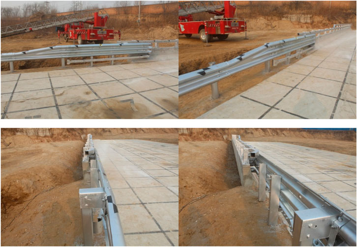
FIGURE 17. Guardrail before the crash test.

FIGURE 18. Guardrail after the crash test.
Figure 19 is the schematic diagram of the moving trajectory of the tractor trailer (right to left).
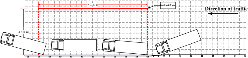
FIGURE 19. Schematic diagram of the moving trajectory of the tractor trailer (right to left).
After the tractor trailer collided with the guardrail, the vehicle did not cross, climb over, straddle, or pass through the guardrail. Instead, the vehicle was successfully redirected without hitting the end of the bridge. By comparing and analyzing the photos of the truck’s collision and the trajectory of the vehicle, we found that after the tractor trailer collided with the guardrail, the guardrail did not invade the passenger compartment, and the soil foundation of the column in the collision area was damaged to a certain extent. Moreover, the column near the end of the bridge was bent more seriously. The collision surface of the guardrail was greatly deformed, and the brackets and friction beams at the end of the bridge played a good role in supporting, buffering, and energy absorption. This indicates that the guardrail in the transition of the subgrade bridge without the wing wall has good blocking and guiding functions for the tractor trailer.
(4) Full-scale crash test results of real vehicles
Table 4 shows the test conditions of the wing-wall-free guardrail in subgrade–bridge transition.
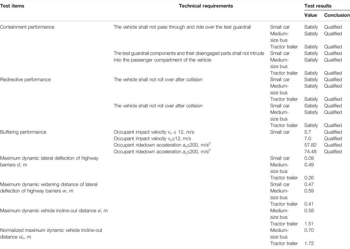
TABLE 4. Test conditions of the wing-wall-free guardrail in subgrade–bridge transition.
According to the vehicle crash tests, the containment performance, redirection performance, and buffering performance indexes of the guardrail meet the requirements of Grade SB protection in Standard for Safety Performance Evaluation of Highway Barriers (JTG B05-01-2013).
Conclusion
To overcome the defects of the bridge barrier’s terminal and avoid fatal injury to the passengers during car crash, this paper has designed and tested the wing-wall-free guardrail in the transition between a subgrade and a bridge. First, through the mechanical analysis of the Q690 material, which is often used in the guardrail, it is found that Q690 high-strength steel has high yield strength, high tensile strength, and good plasticity. Second, the structure of the wing-wall-free guardrail for subgrade–bridge transition has been designed and undergone a numerical simulation before being optimized accordingly into a final design. Third, vehicle crash tests are conducted based on the optimized scheme, and the results verify that the newly designed transition meets the requirements of Grade SB protection in Standard for Safety Performance Evaluation of Highway Barriers (JTG B05-01-2013). Compared with the wing wall transition recommended in current Design Guidelines for Highway Safety Facilities (JTG/T D81-2017), the newly designed transition can connect various bridge barriers, even in the case of a side slope at the subgrade section. The transition has a smooth connection with both W-beam and Thrie beam guardrails. Moreover, no concrete placement or pile foundation is required. With a reduced construction time and reduced organization costs, the newly designed structure saves the funds for the project and is in line with the development concept of “green transportation” in China’s 14th Five-Year Plan. It also meets the goal of resource recycling and low carbon.
Data Availability Statement
The original contributions presented in the study are included in the article/Supplementary Material; further inquiries can be directed to the corresponding author.
Author Contributions
Conceptualization, methodology, resources, and funding acquisition, LS; formal analysis and investigation, RH and TW; data curation, RH; writing—original draft preparation, LS; writing—review and editing, LS and TW. All authors have read and agreed to the published version of the manuscript.
Funding
This study was supported by the research on application technology of the economical high-strength edge-crimped steel guardrail (NO. 2020J-2-21).
Conflict of Interest
Author LS is employed by Rioh Traffic Safety Co., Ltd. Author RH is employed by Transport Development Group Co., Ltd. of Henan Province, and Author TW is employed by Expressway Group Co., Ltd. of Hunan Province.
Publisher’s Note
All claims expressed in this article are solely those of the authors and do not necessarily represent those of their affiliated organizations or those of the publisher, the editors, and the reviewers. Any product that may be evaluated in this article or claim that may be made by its manufacturer is not guaranteed or endorsed by the publisher.
References
An, X., Jiang, H., and Zhang, J. X. (2021). Study on Application of Aluminum Foam to Improve Protective Capability in Transition Section of Guardrail. Highway 66 (11), 6.
Chen, J., Wang, Q., Huang, J., and Chen, X. (2021). Motorcycle Ban and Traffic Safety: Evidence from a Quasi-Experiment at Zhejiang, China. J. Adv. Transp. 2021, 1–13. doi:10.1155/2021/7552180
Ding, F. X., Wu, X., Xiang, P., and Yu, Z. W. (2021). New Damage Ratio Strength Criterion for Concrete and Lightweight Aggregate Concrete. ACI Struct. J. 118 (6), 165–178.
Gilbert, F. K., and Kenneth, J. G. (1985). Explosive Shocks in Air. 2nd ed. Berlin: Springer2 Verlag.
Hallquist, J. O. (1998). LS-DYNA Theoretical Manual. Livermore, California, United States: Livermore Software Technology Corporation.
Harb, J. N., Durrant, S. O., and Terry, R. E. (1993). Use of the Kolb Learning Cycle and the 4MAT System in Engineering Education. J. Eng. Educ. 82 (2), 70–77. doi:10.1002/j.2168-9830.1993.tb00079.x
Kolb, D. A. (1984). Experiential Learning: Experience as the Source of Learning and Development. Englewood Cliffs, N. J.: Prentice-Hall.
Li, Y., Che, P., Liu, C., Wu, D., and Du, Y. (2021). Cross‐scene Pavement Distress Detection by a Novel Transfer Learning Framework. Computer‐Aided Civ. Infrastructure Eng. 36 (11), 1398–1415. doi:10.1111/mice.12674
Lin, Y., Zhong, C., Song, J., and Qu, S. (2021). Experimental Study on the Flexural Behavior of Concrete-Filled Steel Box Slabs. Processes 9 (4), 649. doi:10.3390/pr9040649
Liu, C., Wu, D., Li, Y., and Du, Y. (2021). Large-scale Pavement Roughness Measurements with Vehicle Crowdsourced Data Using Semi-supervised Learning. Transp. Res. Part C Emerg. Technol. 125, 103048. doi:10.1016/j.trc.2021.103048
LS-DYNA (2006). Keyword User’s Manual. Livermore, California: Livermore Software Technology Coporation.
Lu, N., Wang, H., Wang, K., and Liu, Y. (2021). Maximum Probabilistic and Dynamic Traffic Load Effects on Short-To-Medium Span Bridges. CMES-Computer Model. Eng. Sci. 127 (1), 345–360. doi:10.32604/cmes.2021.013792
Luo, Y., Zheng, H., Zhang, H., and Liu, Y. (2021). Fatigue Reliability Evaluation of Aging Prestressed Concrete Bridge Accounting for Stochastic Traffic Loading and Resistance Degradation. Adv. Struct. Eng. 24, 3021–3029. doi:10.1177/13694332211017995
Nicoll-Senft, J. M., and Seider, S. N. (2009). Assessing the Impact of the 4MAT Teaching Model across Multiple Disciplines in Higher Education. Coll. Teach. 58 (1), 19–27. doi:10.1080/87567550903245623
Sasy Chan, Y. W., Wang, H.-P., and Xiang, P. (2021). Optical Fiber Sensors for Monitoring Railway Infrastructures: A Review towards Smart Concept. Symmetry 13 (12), 2251. doi:10.3390/sym13122251
Song, Y. Q., and Deng, C. (2012). Mechanical Mechanism and Numerical Simulation of New Guard Rail of Transition Guardrail. Chin. J. Highw. Transp. 25 (1), 40–46.
Wang, H.-P., Feng, S.-Y., Gong, X.-S., Guo, Y.-X., Xiang, P., Fang, Y., et al. (2021). Dynamic Performance Detection of CFRP Composite Pipes Based on Quasi-Distributed Optical Fiber Sensing Techniques. Front. Mat. 8, 683374. doi:10.3389/fmats.2021.683374
Zhang, H., Liu, Y., and Deng, Y. (2021). Temperature Gradient Modeling of a Steel Box-Girder Suspension Bridge Using Copulas Probabilistic Method and Field Monitoring. Adv. Struct. Eng. 24 (5), 947–961. doi:10.1177/1369433220971779
Zhao, C., Liao, F., Li, X., and Du, Y. (2021). Macroscopic Modeling and Dynamic Control of On-Street Cruising-For-Parking of Autonomous Vehicles in a Multi-Region Urban Road Network. Transp. Res. Part C Emerg. Technol. 128, 103176. doi:10.1016/j.trc.2021.103176
Zhou, Z. W., Wu, X., and Wang, C. H. (2016). Research on Safety Performance of Transition between W-Beam Guardrail and Concrete Barrier. Highw. Eng. 41 (3), 4.
Keywords: guardrail installation, simulation, vehicle crash test, the wing-wall-free guardrail, structural optimization
Citation: Shen L, Hu R and Wang T (2022) Research and Design of a Wing-Wall-Free Guardrail in Transition Between the Subgrade and the Bridge. Front. Mater. 9:918107. doi: 10.3389/fmats.2022.918107
Received: 13 April 2022; Accepted: 06 June 2022;
Published: 13 July 2022.
Edited by:
Ping Xiang, Central South University, ChinaCopyright © 2022 Shen, Hu and Wang. This is an open-access article distributed under the terms of the Creative Commons Attribution License (CC BY). The use, distribution or reproduction in other forums is permitted, provided the original author(s) and the copyright owner(s) are credited and that the original publication in this journal is cited, in accordance with accepted academic practice. No use, distribution or reproduction is permitted which does not comply with these terms.
*Correspondence: Tingyu Wang, wty20220331@163.com